
 By Bob Colegrove
A DXer recently posted the following question on the Internet: “Why do I get a much stronger signal if I clip a long wire to the telescoping antenna than if I connect it to the external jack”? He then postulated that this might be due to different input impedances at each point. Different receiver input impedances could affect the performance of a long wire antenna at a specific frequency.
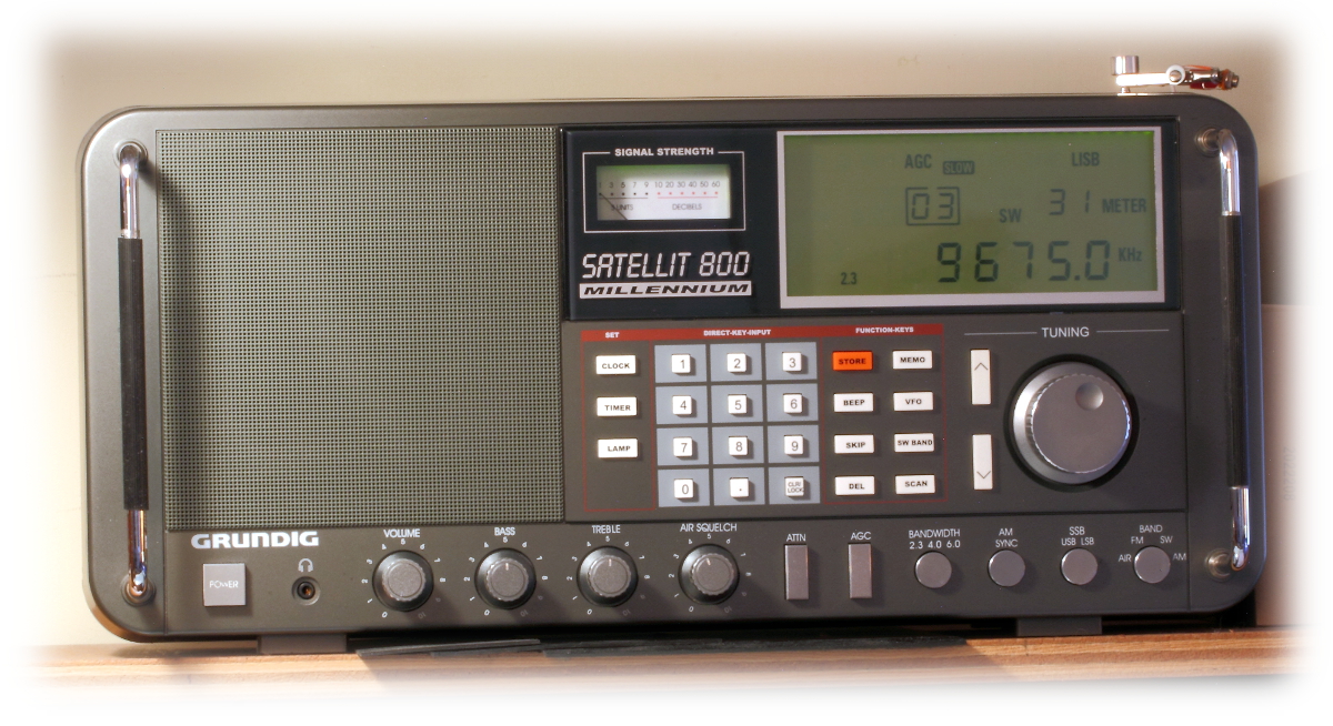
The question reminded me of an experience I had a few years ago with both the Grundig Satellit 750 and 800. Different radios than that in question, but the same results. What follows describes a little-known feature I stumbled across (no claim to discovery) on the Satellit 750. Later, when I got a Satellit 800, I found it also worked on the older big brother.
The 750 and 800 radios share similar appearances and many of the same features, among them the various antenna input options, including a 50-ohm SO-239 for LW, MW, and SW; a 500-ohm pair of compression clamps for long wires when tuning the same bands; an F-connector for VHF; and a lengthy whip antenna which can be used on any band. Input selections are made with a pair of switches adjacent to the terminals on the back or side of the radio.
To mitigate noise, I use resonant loops to the exclusion of almost everything else. Just for fun, I tried the whip antenna as an input for a loop. Understand that the whip is a single-pole, electric field probe. There is no accompanying ground, or, as it is more euphemistically termed these days, a “counterpoise.” Thus, for application of a dipole or loop antenna, one must find a counterpoise. This was easier than expected, as it turned out to be the otherwise unused compression ground terminal for the 500-ohm input. When coupling antennas on radios, it does not always have to be invasive. I managed to temporarily jury-rig the connections to the loop antenna. The receiver came alive.
What’s going on here? A check of the block diagram and schematic provided the answer. The circuit for the radio’s whip antenna input contains an additional RF amplifier stage, which is not used for either the 50- or 500-Ohm external antenna inputs.
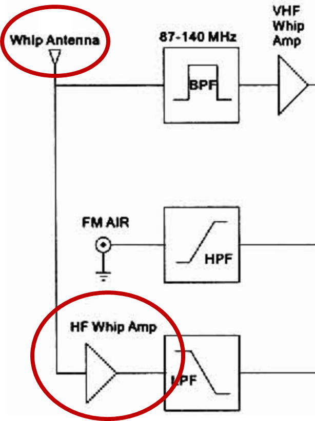 For anyone interested, the easiest download for the block diagram (Sheet 2) and RF schematic (Sheet 4) is at https://elektrotanya.com/grundig_satellit-800_sch.pdf/download.html#dl. These drawings are labeled for the Chinese Ham-2000 branding of the Satellit 800 and are fuzzy but readable.
Besides this subtle suggestion, the only other clue I have been able to find for this circuit came from the review in the 2002 edition of Passport to World Band Radio. “Weak-signal shortwave sensitivity with an external antenna can be boosted by setting antenna switch to ‘whip,’ thus adding preamplification…” (p.129); [sic] and using the whip for the input.
The effort soon became one of rendering the connection between the loop (or any dipole) antenna and the receiver more permanent. There was a time when I might have violated the integrity of the radio and done a proper job of it. A proper job would be to completely bypass any potential unshielded source of RF, in this case, the whip itself, and connect a shielded lead-in directly to the amplifier. At this point I didn’t want to make any permanent alterations to an otherwise museum-quality unit. Truth be told, I’ve grown averse to exertion of any unnecessary effort. The result is certainly not elegant. Further, the lack of shielding around the exposed whip might potentially compromise the results. Nevertheless, the kluge pictured below was fabricated and works surprisingly well, maintaining normal peak and null responses from the loop.
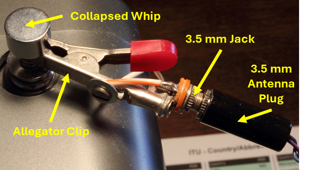 The ”hot” terminal of a 3.5-mm jack, compatible with the plugs on my antennas, has been soldered to an alligator clip, which, in turn, is connected to the top of the collapsed whip antenna on the radio. The “counterpoise” is a short piece of hookup wire connected between the ground lug on the 3.5-mm jack and the grounded compression terminal on the radio. Without a counterpoise for a loop or dipole, it will simply act as an electric field extension of the whip. The only other requirement is to set the “SW” switch (also used for LW and MW) to the “WHIP” position.
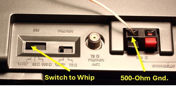 If you’re working with a long wire (monopole), forget all that stuff above, and just clip the wire to the top of the whip. I will add a caution about connecting long wires. Semiconductors are vulnerable to high voltage input. Electrostatic discharge, either atmospheric or bodily, has been known to ruin input circuits. Fortunately, this does not appear to be a problem in recent years, and the external wire packed with your radio is likely quite safe for experimentation.
I am not a big fan of active antennas, feeling they are often a source of additional noise. However, in the case of this little deviation from the normal antenna inputs on these radios, the amp is already there, and the result has been very satisfying, proving once again that a bit of tinkering in this pastime is sometimes advantageous. Note: For many portable radios, the whip input does not work on LW and MW, so this approach will only apply to SW.
If there is a point to this posting, it is in the form of a question: Are there any other radios having one of their inputs augmented (amplified) – likely the whip? The fact that a radio is equipped with a whip antenna indicates that, by design, it is intended to be portable. For LW, MW and SW, this means whip antennas pose an acceptable operational handicap. This compromise permits the listener some flexibility to move around with the radio. So, it’s reasonable that designers may have chosen to augment the whip with some internal amplification.
Finally, don’t give up on an antenna input which appears to be less sensitive. It may be more responsive on a different band, or it may mitigate overload produced by the hotter input. Whether it’s a case of different input impedances or an extra RF amplifier inserted on the whip, it’s in a DXer’s interest to find out if performance differs for each input on their own radio.
Thank you for the very informative article! As you have demonstrated, a receiver is only as good as its antenna and how it is connected. I have been using a Tecsun S2000 (Eton 750) for 10 years now & one of the reasons I chose it as my everyday radio was the good choice of antenna inputs to handle my outdoor antennas. Like any radio, it has a shortcoming or two but teamed up with my MFJ 1886 loop, it does a fine job, especially on MW. The Par-EF-SWL does a nice job on SW too.
Excellent article, and great information. Like you I do not wish to tear into radios anymore, and especially classics like the 750.
Cheers!
When I lived in the mountains, I used an end fed Zepp fed with ladder line, a fancy way long wire antenna. Static electricity would build up on the wire due to charged dust particles in summer or snow in winter.
When it had built up enough, a spark one inch long zapped across the terminals of my antenna tuner. The solution was to put a 1 megohm resistor across to bleed the high voltage and not let it build up.
Be warned, a long wire suspended outside can have thousands of volts on it. The preamp on the whip antenna will be toast before you know it. Don’t let the magic smoke out of your radio.
A notable example was the Sony ICF-2010. Still regarded as a premium multi-band portable after more than 40 years, they lacked any protection on the external antenna input. The whip was protected by a pair of diodes which seemed to do the job, but a wire of even a few meters could easily zap Q303 on the external input circuit. You could also cause mischief by shuffling over a carpet in the winter time and contacting the external input. I was bitten by this snake not once, but twice. At the time, Sony still maintained a service center in the area and my units were restored for a price.