
 Many thanks to SWLing Post contributor Alfredo (EA4IMN), who writes:
Hi Thomas,
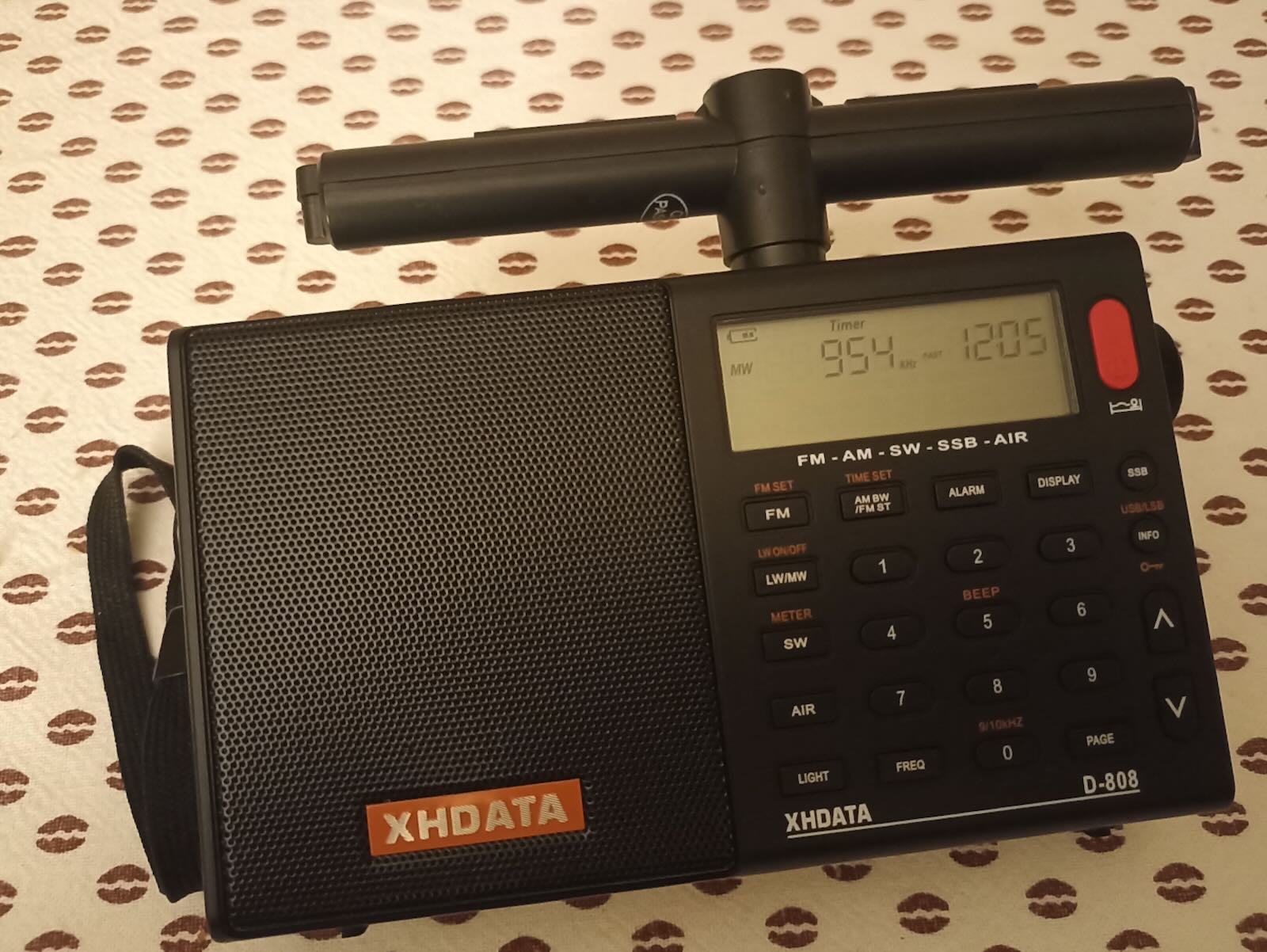
Greetings from EA4IMN. I recently purchased an XHDATA D-808, and got puzzled by the absence of an external jack for the LW/MW antenna. Inspired by previous work, I set to add this feature to my unit.
My journey was overall straightforward, but not without some hacking required, so I’m sharing my experience here, in case it helps others. (I have briefly documented this on another forum, but here you are the abridged version of the story.)
First, let’s start with a pic of the pristine PCB:
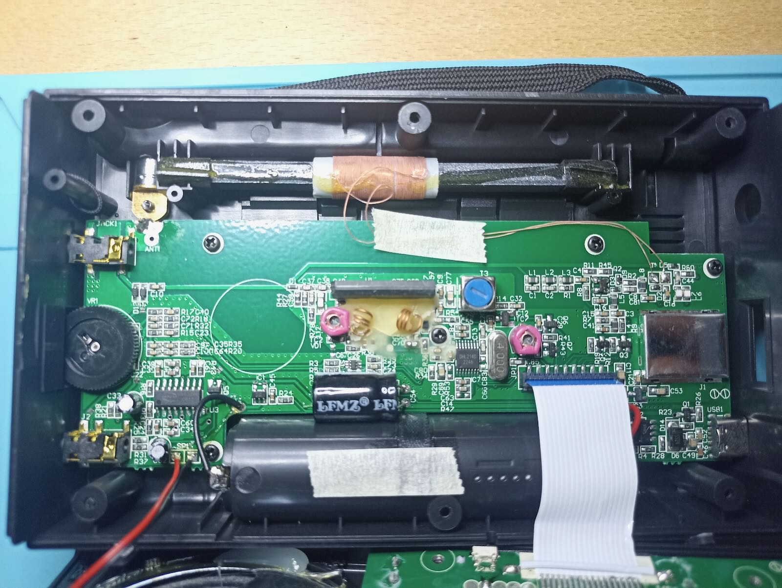
It’s a recent unit, and I observe it has minor differences even from some USB-C variants I could find on YouTube. I assume XHDATA keeps tweaking the inner design, and that’s not documented.
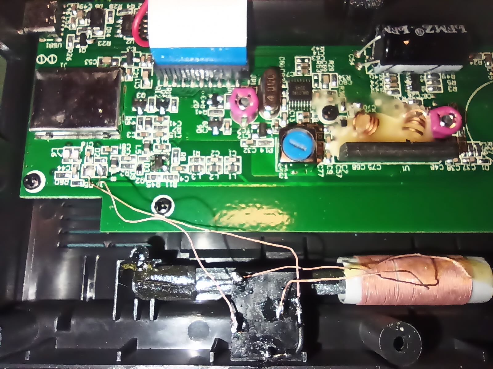
In the “external MW Jack” picture [above], you can see how I added a 5-pin female jack. Interestingly, I could entirely reuse the litz wires that came with the internal ferrite antenna. It works as follows:
- When no male jack is inserted, the internal ferrite antenna is directly connected to the antenna pads on the PCB.
- When a male jack is inserted, the internal ferrite antenna gets disconnected, and the PCB pads take the signal from the external antenna connected to the male jack.
Since I wanted to be able to also connect a long-wire, it was crucial to correctly identify the “hot” pad on the PCB, so that it would be wired to the tip of the jack (and not to the sleeve). It turns out that, on my unit, the squared pad was connected to GND.
I recommend anyone wishing to do this mod to verify the pad layout on their unit, since the PCBs keep changing. This is how to do it:
- Pick one litz wire of the internal ferrite antenna and cut it. Make sure to cut it at a point that will later allow you to solder both ends to any of the 5 pins of the jack (you still don’t know if you cut the hot or GND wire!)
- With a multimeter, check for continuity between the antenna pads and a well-known GND pin. In my unit, I used the audio amplifier chip, the CS8573E, for which datasheets are available, to check which pins go to GND. (Note: I first tried to check continuity with the negative pole of the battery, but that didn’t work, likely due to the battery recharge circuitry.)
Also, I recommend soldering the sleeve and ring pins (you can see a black wire in my picture): some ferrite antennas come with a stereo jack where the ring is floating, so the added wire makes sure all jacks are treated as mono, by shorting ring and sleeve.
Now… closing the unit was an issue: the 5-pin jack I just added clashed with the display! I had to get creative in a few ways:
- Bend three pins in the jack that were clashing against the display. That made them just lower enough that I could “gently push” the case so that it would close.
- Yet, the pins were now touching the metal cover of the display, hence shorting together, and nullifying the antenna! That was sorted by covering the metal plate with insulating tape. I had to add a couple of layers, since the soldered pins had rough edges that would keep piercing into the tape…
In the end, it all looked good to me, as depicted in the “Final result” photo:
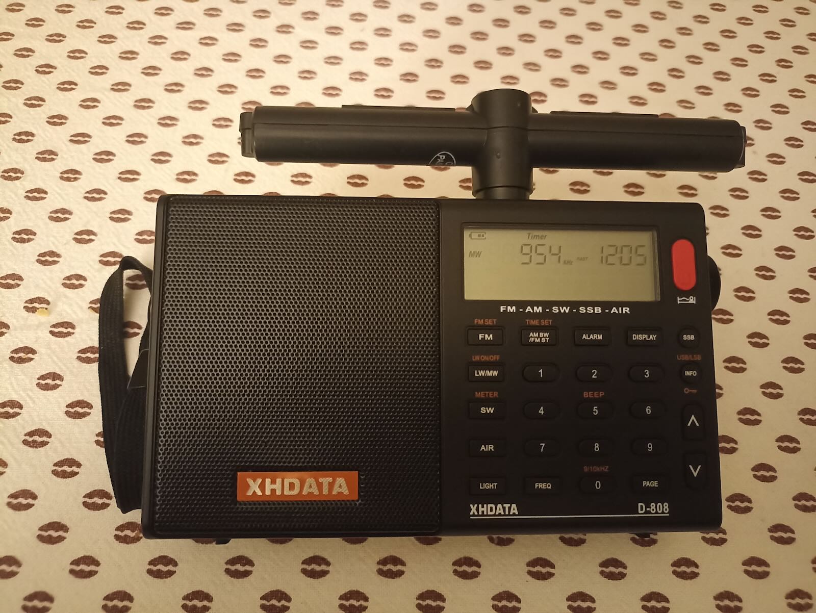
Admittedly, the external ferrite antenna in the picture performs roughly the same as the internal one. But at this point, it’s just a matter of plugging another jack and keep experimenting!
73