
Many thanks to SWLing Post contributor, TomL, who shares the following guest post:
Backpack Shack 2.0
by TomL
Like Audiophile speakers, it could be said that “antennas are forever”. They tend to not become obsolete like all of our favorite electronic gear (a good one is worth the trouble). And antennas don’t care if the signals are digital or analog formats. They are “Digital Ready” (LOL)!
The flimsy “Backpack Shack” prototype broadband loop antenna created over a year ago had found a permanent home on the porch for general listening. I started itching to make a new one that was even more portable. To paraphrase an old saying, “The best antenna is the one you have with you!”
The new design criteria were:
- Retain the broadband design of the amplified loop on a sturdy form
- Shrink the size to fit into a backpack without heavy stand or long pole
- Build a modular platform that would allow quick setup
- Be something durable that can last me 20+ years of use
- Allow the loop to be rotated and tilted by hand
- Be easy to hook up to any kind of radio
- and later on, Enhance the design as a true Ferrite Sleeve Loop
The Backpack: The existing photo backpack was slightly too bulky. Found on Amazon was an Adidas Excel II XXL backpack on special sale with plenty of tall compartments and minimal padding. It is surprisingly roomy and comfortable to wear with springy shoulder straps and padded mesh backside!
Sturdy Basic Form: The Backpack Shack loop was originally built on 14-inch quilters loops (three of them) in a parallel configuration. I thought to simplify the whole thing and just use one wide loop. But what should I use for a sturdy form? The quilters loops were too flimsy and PVC pipe was too heavy. I stumbled upon a nice company called FlexPVC which allows sales to the public of various kinds of PVC pipe. Their Thinwalled Air Duct PVC looked promising. It is thinner than regular PVC but having standard inside dimensions and comes in custom-cut lengths. I decided 10-inch diameter would fit best inside the Backpack. FlexPVC even sends you a small booklet of the U.S. Constitution and the Bill of Rights with your order! 🙂
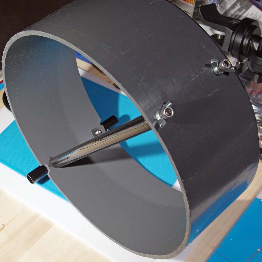
Thinwalled PVC form
The “length” as they call it would be my form width for the copper strip. I thought 3-inch would be nice but decided 4-inch was better. Supposedly, the aperture + the width of the “radiant element” is the main design consideration for loop performance. So, I figured that as wide an element as I could get away with was better.
Stable Mounting: Now, how to mount this thing! I eventually went back to my photographic web links and found nice rig equipment for video cameras. The typical construct is made of 15mm tubes of aluminum or carbon fiber (CF) and fit into adapters that allow attachment to other adapters or clamps. Non-metallic CF seemed ideal, so, I ordered a whole bunch of items from eBay to experiment piecing together two 10-inch CF tubes mounted inside the PVC form. Then, I attached two 15-inch CF tubes to the bottom of the PVC with something called a “Cheese Rod” that has multiple holes. Those two tubes are attached to another “Cheese Bar” which is attached to a second Cheese Bar on a cheap two-axis tripod head. This is a simpler photo version with quick release plate that locks pan-tilt separately and only cost $16.
Cheese Rod attached to bottom of PVC
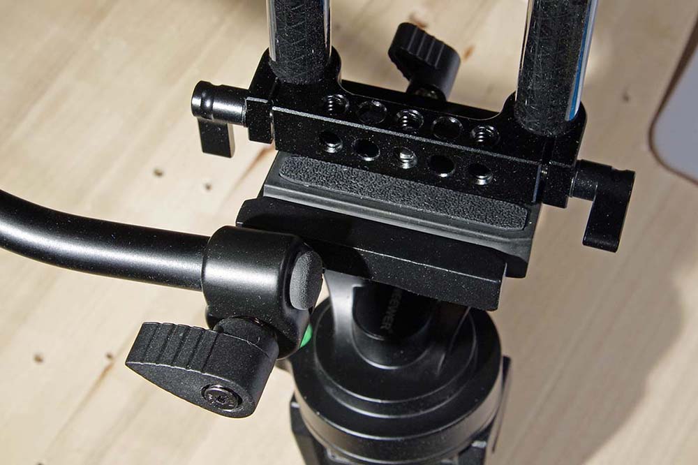
Pan-tilt head assembly with Quick Release plate
For the base, I had an unused Sirui T-2005X 5-Section Aluminum Travel Tripod going to waste, so it was pressed into service. Very good tripod: can hold 26 lbs. (forged aluminum, not cast aluminum), legs can flare out for stability, and folds to 14.5-inches. Now, everything could come apart and fit into the Excel II Backpack!
Critically, the video rig standardization in the DSLR industry allows me to pick and choose parts from any cheap manufacturer but end up with a system that looks and feels coherent, is both sturdy and light, and can come apart if needed. Also, the pan-tilt photo head is really easy to work to get maximum peak or null out of the loop when mounted to a camera tripod.
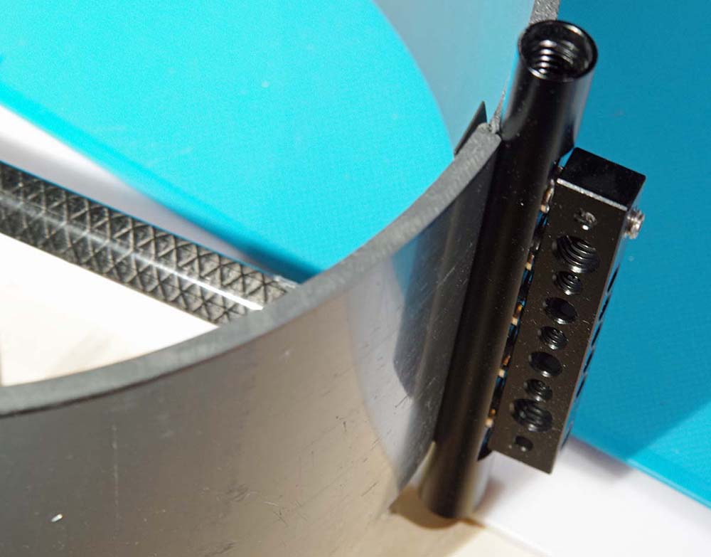
CF Problem: CF tubes have no internal threads like that of aluminum tubes. So, I attached two, small 3/8-1/4 inch tripod adapters to the ends of a 3/8-inch oak dowel inside each CF tube destined for the inside of the PVC (ridiculously, I used up almost a whole bottle of super glue to get these 4 tiny pieces to attach to the oak dowels). This is definitely a weakness of my design but I could not figure out any other way to get the CF to mount inside the PVC form. Then, added to this is something wonderful I found at Ace Hardware called “speed nuts” to help push ipwards against the incoming stainless steel socket head screws of exact length. With jam nuts, internal lock washers, wing nuts, and strategic use of Thread Locker Blue, I finally had enough confidence that this thing would hold together!!
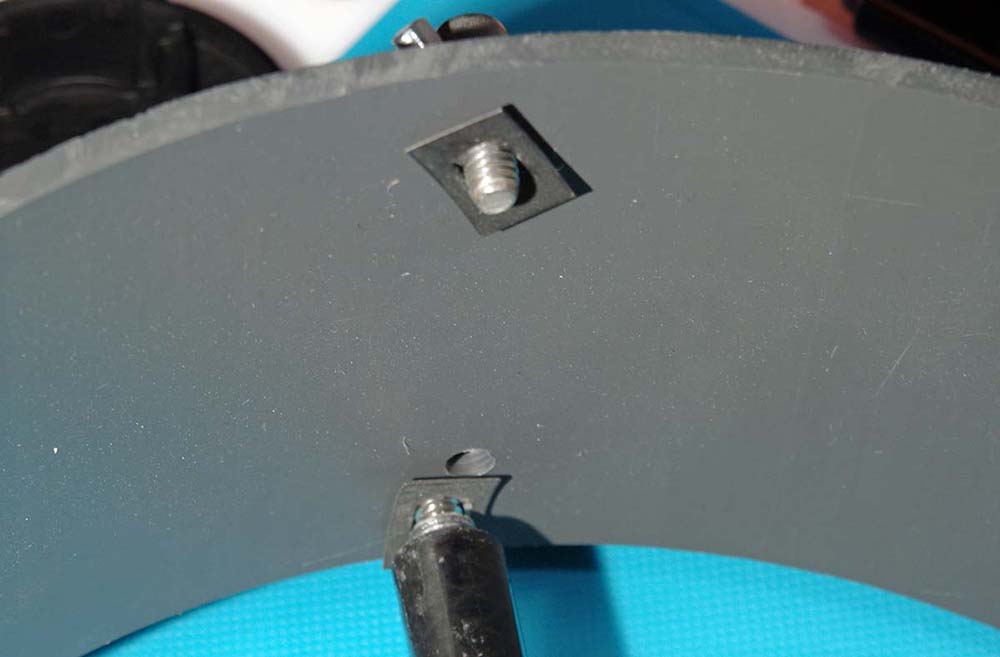
Speed Nuts pushing upward against incoming screws
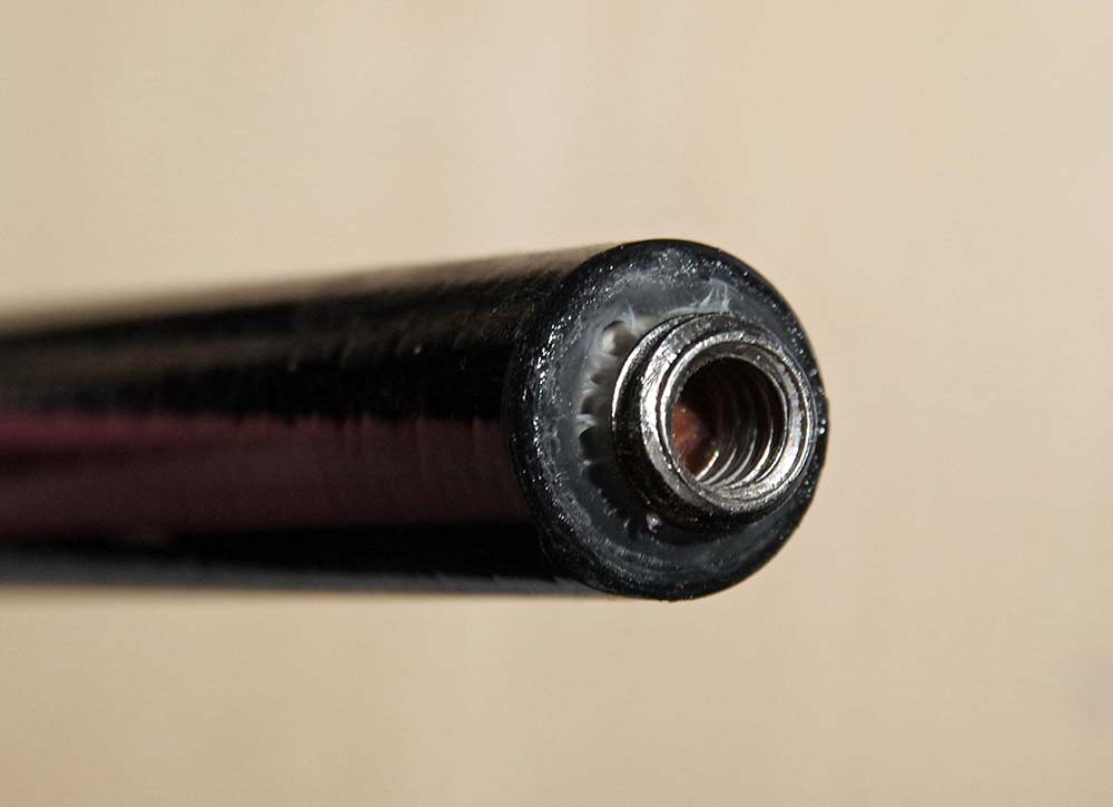
Super-glued 3/8-1/4 inch adapter on end of oak dowel inside CF tube
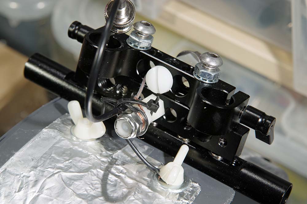
Bottom assembly (Cheese Rod, Cheese Bar, and 15mm Clamp screwed together + wires to a BNC connector)
Ferrite Sleeve Loop: Halfway through this project, I became determined to use the ferrite bars and rods I had purchased from eBay mid-summer 2017 to turn this antenna into a real Ferrite Sleeve Loop but with a broadband design (At that time, I ended up purchasing the very last quantities of 62x12x4mm ferrite bars from the Lithuanian eBay seller, just because they were becoming scarce plus some other 8mm ferrite rods). The Thinwalled PVC is 5mm thick, perfect for this type of application. The video equipment could handle the extra weight. I had just enough ferrites to line the inside of this PVC form with two bars side-by-side all the way around the inside (plus some shorter ferrite rods at the top and bottom). Some quick setting JB WELD Kwik Weld epoxy made quick (and permanent) attachment of these ferrites to the inside of the PVC. Now, the bars stick out from the PVC form by about ½-inch on each side, so I do have to be careful it does not get abused and chip off any of the exposed ferrite.
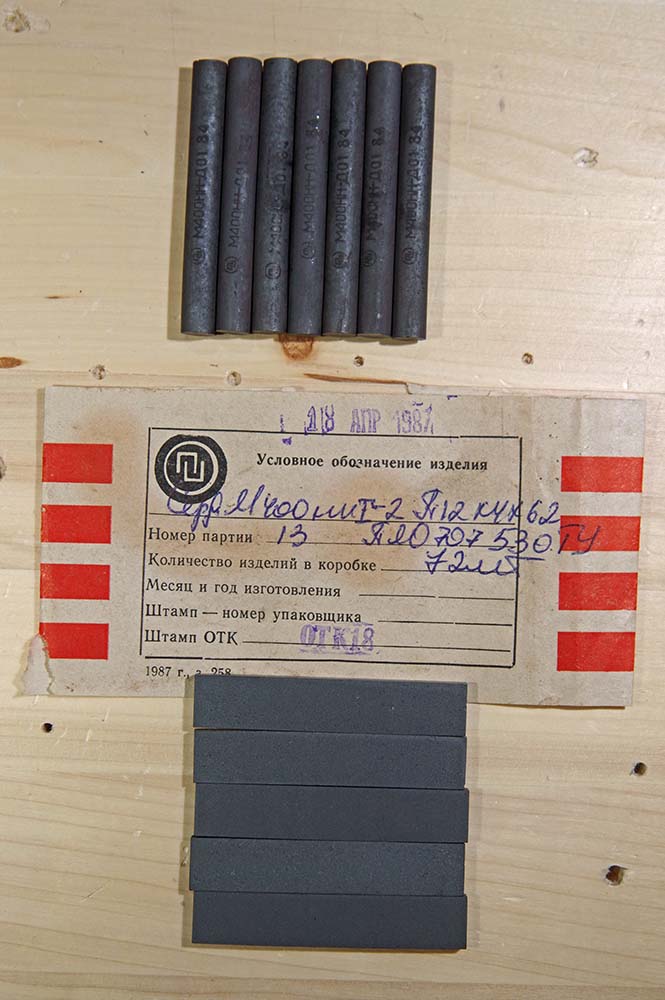
Soviet ferrite bars and rods, 400 ui (initial permeability).
Note: Using Gary DeBock’s Performance estimate (diameter * length), this calculation predicts that this FSL 10.75-inch loop should perform similarly to Gary’s 10-inch models using 140mm long Russian ferrite bars (mine probably performs less than his since I am not using carefully tuned (to Mediumwave) litz wire on higher permeability 1500 ui ferrites like he does).
See: Summary of Gary DeBock Ferrite Sleeve Loop designs
But, “*WHY* do FSL antennas work?!?!” is still the very intriguing question…. 🙂
See: Graham Maynard report on Ferrite Sleeve Loop antennas
Preamplifier: I believe one advantage of building a portable, table-top loop antenna like this is that all the connections are short. This allows me to use a Preamp right at the connection point of the loop. Indeed, this was critical since passive testing (no Preamp, nor ferrites) found that this loop is somewhat deaf at the MW frequencies and uninspiring on the SW bands. This was true even when connected to Antenna A of my SDRPlay RSP-2 and the internal Low Noise Amp cranked all the way up. So, I ordered the DX Engineering RPA-2 Preamp. This adds to the weight somewhat since I also needed a 12V battery supply using a 10-cell holder of NiMH AA batteries and 2.1mm plug.
See: Short discussion about Preamp placement to antenna
The question arises that I “should” impedence-match the output of the loop before anything else to increase “maximum gain”. Well, for one thing, a tuner or matching balun would just introduce loss as soon as the wire comes out at the base of the antenna. The slight net increase in gain does not seem worth it; the signal/noise ratio rarely changes when introducing a device that is meant specifically for matching a transmitter to a load. Receiver circuits don’t care as long as there is enough signal to process. That is what the Preamp is for. The Preselector is for rejecting out-of-band (i.e., increasing signal/noise ratio + eliminate overloading the electronics).
See: Good discussion why antenna tuners don’t matter
Preselector: Now that the signal level was satisfactory, I added on the Cross Country Preselector, which I like very much since it is passive, lightweight, and well made. I had looked at other amplified preselectors but found the schematics showing the preselector came first in the path. I needed the preamp first, so that is how I ended up with separate units. In fact, the reverse configuration performs with worse signal/noise ratio because of the loss inherent in the preselector. In this case, it is definitely needed to amp the loop first with a high quality preamp (high IP3 rating)!
Automatic Bypass: The Cross Country unit has a great feature in the “off” position as an automatic bypass. This feature is very important since I do not need a Preselector in the circuit all the time. The bypass feature also allows the RSP-2 to monitor a large swath of spectrum without having the Preselector cut the bandwidth. The DX Engineering RPA-2 Preamp also has a circuit bypass when the power is off – very nice feature! So, I can keep all the antenna wires connected if I don’t want to use either device on a certain band – necessary for my broadband antenna design and use with an SDR.
Modular Portability: Another advantage of a table top loop is portability. Because of the modular design, I can put this into checked baggage (except for the AA batteries and laptop) and have it available for DXing in unexpected places. It could be useful when traveling and I cannot string wire into a tree but want something better than a whip antenna on a small radio. Everything fits into the bag and can be setup on a balcony, inside a car with a sunroof, or on a park picnic table.
A third advantage is that a short antenna could be clamped to one of the tubes and then connected directly to Antenna B of the RSP-2 for listening to higher frequencies (like a Comet W100RX). This expands the usefulness of this project as a platform for multiple antennas!
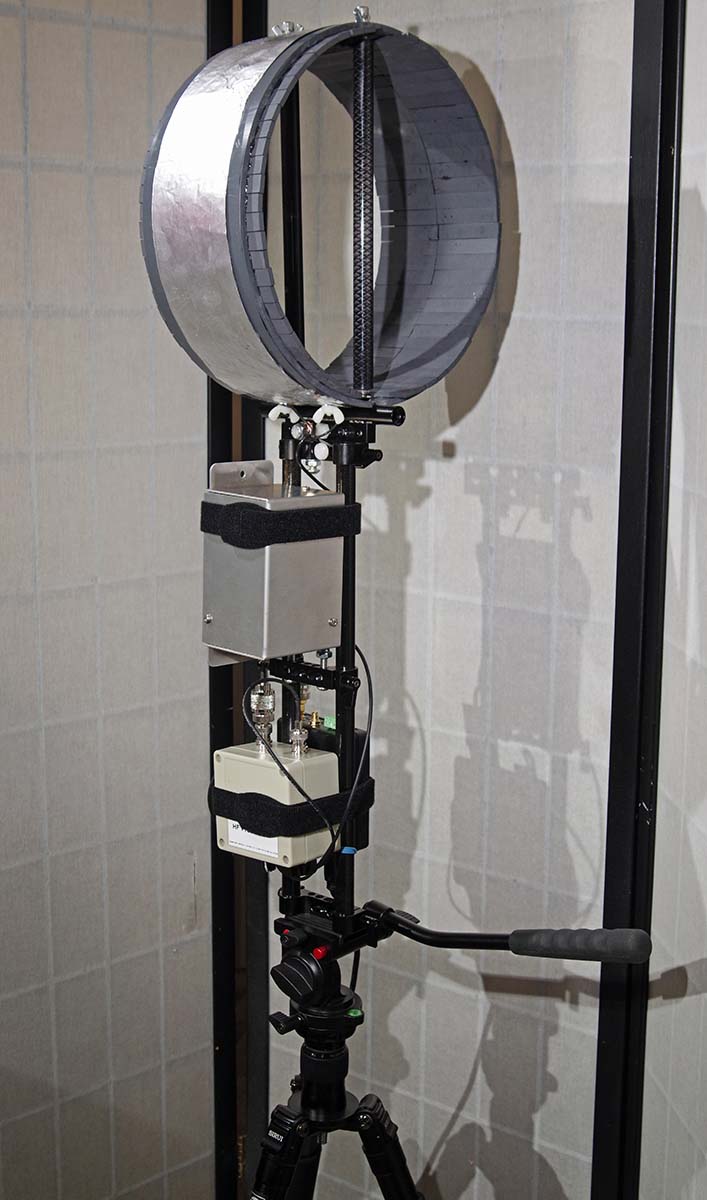
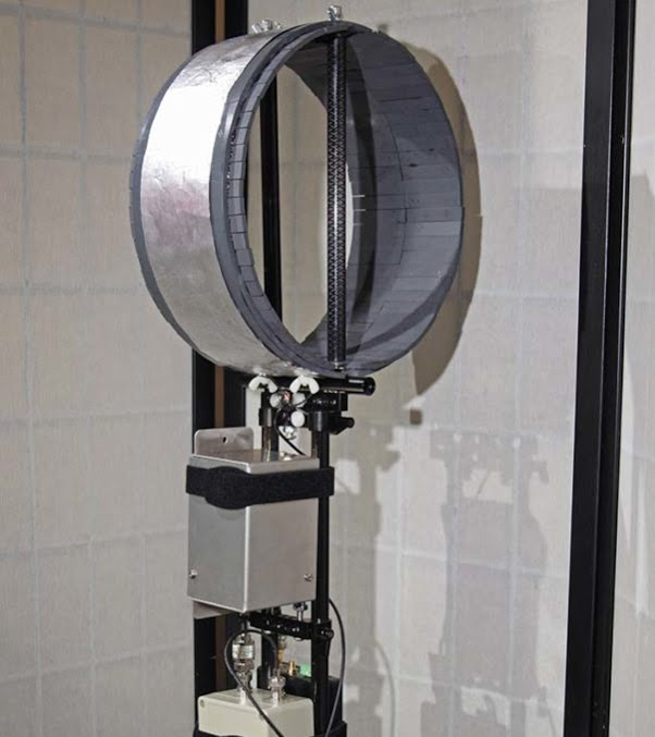
Finished Loop and accessories assembled together
Performance: Good on MW and very good on Shortwave. It is not in the league of Wellbrook antennas but it is useful as long as the RSP-2 LNA is kept down around -7 on MW and -4 on SW, else it overloads. The photo gear makes it easier to use than the original loop. I found that one side has a slightly larger receiving lobe than the other which is OK in practice. The null is very sharp and takes a little finesse to null out an offending station by almost 20 dB on MW and 15 dB on SW (the photo head can lock in place). It is handy to have the pan-tilt arm point directly at a station to maximize the null since the arm is mounted perpendicular to the loop. I will look for a clear plastic bag to cover the antenna and electronics to use in wet environments.
A larger loop would work better but this one is to use wherever I can. Also, my work laptop is noisey and shows birdies and spikes here and there on the bands, so I added a large ferrite bead to the USB computer end which helps. But I don’t have to use an SDR, I just have to change a connector and radio. It was expensive and fun to build – I guess I am just LOOPY!
Happy Listening,
Tom Lebryk
Appendix I, Field Recordings 27-Jan. 2018 between 21.26-22.36 UTC:
Note 1: All Transmitter locations referenced from web site short-wave.info at time of recordings
Note 2: My location in a shelter at Dick Young Forest Preserve (41.84334, -88.38133)
Note 3: Moderate but declining solar wind with no flares, Kp Index = Calm (1)
9.420 MHz – Voice of Greece booming in like it was next door:
9.640 MHz – China Radio International (weakly) in Spanish from Kashi-Salibah western China:
9.620 MHz – HCA, Kununurra Australia beamed at Korea:
9.395 MHz – WRMI booming in:
9.445 MHz – All India Radio clear as a bell, quite nice to hear!
9.490 MHz – KNLS World Christian Radio, Madagascar in Chinese:
9.600 MHz – Vatican Radio, Tinang Philippines in Chinese:
9.610 MHz – Voice of Turkey, Emirler Turkey (endless string & flute music):
15.000 MHz – WWVH, Hawaii (halfway, I checked on WWV at 10 MHz to make sure it was on the air, weird propagation, defintely not due to my antenna!):
Appendix II, Parts List:
- 1 FlexPVC 4-inch Custom cut X 10-inch diameter Thinwall Air Duct PVC
- 1 pair each size of 15mm CF rods 10-inch and 15-inch
- Video Camera Rig parts: 2 Cheese Bars, 3 Rod Clamps, and 1 Cheese Rod
- 1 cheap Neewer pan-tilt photo head with quick release plate
- 10 screw adapters for tripods 3/8-to-1/4 inch
- 1 copper sheet roll cut to size (or Aluminum foil instead)
- 4 Flat Speed Nuts 1/4-20 from Ace Hardware
- 1 Oak Dowel 3/8” diameter from a local hardware store, cut as needed
- 1 DX Engineering RPA-2 Modular Receive Preamplifier
- 10 AA Powerex Precharged NiMH batteries for the Preamp + 10x AA snap battery holder + CCTV 2.1mm snap plug
- 1 Cross Country Preselector
- 1 SDRPlay RSP-2 with SDR Console software on Lenovo laptop
- 1 Belkin USB printer cable with large ferrite bead looped through 3 times on computer end
- 1 Sirui T2005X travel tripod
- 1 Adidas Excel II XXL backpack (gaudy Solar Orange color!)
- Velcro brand 7/8” x 23” One-Wrap velcro strips
Plus shielded cables, BNC and SMA adapters, Thread Lock Blue, tie wraps, rubber bands, super glue, JB WELD Kwik Weld epoxy, speed nuts, jam nuts, acorn nuts, wing nuts, internal lock washers, nylon nuts and screws, and 1/4”-20 socket head screws of various lengths as needed.
What a brilliant project, Tom! What I love is the fact that you consider your unique requirements prior to starting a project and base your design on your specific needs. Additionally, you see each design as an iteration. Fantastic job! No doubt, you’ll log numerous hours with this antenna in the field! Thank you for sharing your detailed design notes, process, list of materials and even audio clips with us.
Addendum: 12V not best for the DX Eng. preamp. It likes 13.8V – 18V, so I have been using 4 lithium 14500 cells (VERY carefully) in 4 AA cell enclosure with on/off switch. Only lasts 1/3 as long as the NiMH, so I have ordered a 12-cell battery holder for the NiMH AA cells from eBay for those occasions when I need longer runtime.
Tom., have you ever thought of using a small LiFePo battery for your setup? They’re very lightweight, stable and you can use them for a number of other applications. They’re not cheap, I should mention however. 🙂
Thomas
Thanks, Thomas! That is an interesting suggestion. The larger sizes are not very portable but I can experiment with the smaller 14505 (AA) size if I use 5 of them and a AA dummy in a 6-cell holder. At the moment, I have a nice compact 4-cell holder enclosure with on/off switch that protects the 4 Li-Ion 14500’s and seems to last about 4 hours of juice Max.
Cost still is cheaper with NiMH. For instance, on the batteryspace.com site, they have a nice LiFePo4 15Ah pack for $287 = $19.1/Ah. The XStar Li-Ion’s I bought last year are about $20/Ah. Just tonight, I bought from Amazon 16 Tenergy Centura D-cell (LSD type) for $93. At 8Ah that’s $11.6/Ah (and I only need 12 for the preamp, I can use the other 4 in a large flashlight). And the Tenergy Universal charger only cost me $20!
I have a nice surplus Verizon Cable battery case that can fit 16 D-cells and closes nicely and has its own on/off switch. 8Ah should last me about 48 hours! So, I think there is enough choice now to do this without extra kinds of chargers and sizes of batteries. Maybe I can publish a report on the Verizon battery case if it works out OK. Power in the Field is always an issue!! And maybe I can use a second one to power the small netbook as well (for camping purposes)?
https://www.ebay.com/itm/CyberPower-CyberShield-DBH36D12V-D-Cell-Battery-Holder-Shield-Verizon/192436123327?epid=1357887073&hash=item2cce1636bf:g:-GoAAOSw9p9aZ5N7
That sounds like a plan!
BTW: the batteries I had in mind were the type like you can find at BioEnno:
https://www.bioennopower.com/collections/12v-series-lifepo4-batteries
But I now realize the output voltage is exactly 12V, not 13.8, so this would not work for you. I have this 12aH version and use it for QRP field work:
https://www.bioennopower.com/collections/12v-series-lifepo4-batteries/products/copy-of-12v-12ah-lfp-battery-pvc-blf-1212w
Cheers,
Thomas
Correction – my mistake, the surplus Verizon Cyberpower case fits 12 D-cells, which is still good enough. 1.2V*12=14.4V
My colleague at work, Brian ( who is smarter than me), immediately saw that I can ditch the tripod and 15 inch tubes and just leave the loop inside the backpack. I cannot see why that should not work. I might just have to make a belt holster for the preselector if I want to include it and then carry the small laptop in one hand. Something to experiment on.
Hi TomL and Ray,
I indeed experimented with an attempt at “broadbanding” a FSL antenna some years ago. The key, I *thought*, was to take advantage of the input impedance and the amplification of a Wellbrook FLG100LN antenna module connected to the Litz wire coil of the FSL. Long story short, the antenna worked only modestly in broadband “mode”, unless artificially enhanced by an excellent DX spot like the Rockworks cliffs in Oregon.
I haven’t pursued this further, but perhaps a broadband approach to the FSL would be improved with a coupling coil of an appropriate impedance match. Here is some information shared a few years ago by Everett Sharp, N8CNP… he may be on the right track with this:
“A few years ago I did a lot of experimenting with pick up loops for both FSLs and air loops. The problem that I had was similar to yours. When I tried connecting the pick up loop to the 50 ohm input to my Icom R75 it loaded the loop, or FSL to the point it was almost useless. Through experimenting I finally came up with a solution by using a matching transformer transformer, made using a ferrite binocular core (BN73-202) and winding it with 2 turns on one side and 16 turns on the other side, which gave me a ratio of 64:1, or 50/3200 ohms. The 16 turn side was connected to the loop and the 2 turn side to radio.
How I arrived at the turns ratio was I connected a RF Meter to the loop tank circuit, tuned it to a local radio station and by experimented with different turns ratios until I found a combination that would give the radio a good signal and caused the least amount of voltage droop on the loop tank circuit.”
Everett’s approach was for a standard tuned FSL antenna, but maybe the 64:1 ratio coupling coil could help a broadband version? If so, what would the main loop’s coil be connected to then? In my attempt the FSL’s coil wires went directly to the terminals of the FLG100LN module.
One thing’s clear– a broadband FSL antenna is begging for experimentation by some intrepid radio hobbyist!
Guy, that is excellent info! It seems technology has advanced leaps and bounds, but antennas not so much. More research is needed. It remains to be seen if a matching transformer can be made that is broadband enough since they tend to be limited in frequency range. But I have trouble getting my head around the electromagnetic engineering theory. Somehow broadening the response without overall introducing loss is one of the needs.
Shortwave performance seems good to me. Maybe I will try an antenna tuner in front of the preamp to see how MW performance behaves….
Nice design but I think you could do a lighter antenna by using a coaxial ‘shield’ loop design. I’m not sure such antennas will be comparable to your ferrite rod loop you’ve constructed but I suspect it would be a good deal easier to assemble and you can still use the preamp you’ve bought with it easily.
Thanks for the idea which I had considered but I really wanted to build a “fat” loop to lower the inductance. Also, I wanted to make sure it was going to be a Ferrite Sleeve Loop. Leaving it inside the backpack and ditching the tripod and 15″ tubes is saving a lot of weight!
I thought all magnetic loops required a variable capacitor unless tuned for a specific frequency How does this work without a var-cap?
Did you read the link he gave which addresses that question?
Short version:
Making the antenna resonant gives useful Selectivity, but cannot improve the Sensitivity.
As long as tuning doesn’t affect the impedance match, it cannot magically add any signal.
I am not an engineer nor an amateur radio operator (ham), so I don’t know all the theory. I am just following the lead of Graham and Gary in how to build an FSL. Also, Gary’s friend, Guy Atkins, built a broadband version using a Wellbrook amplifier (described at the bottom of my link to Gary’s Summary). Guy had good success and someone else made his own version (Walt Salmaniw). So, there is precedent and theirs were optimized with specific lengths of litz wire for Mediumwave reception.
I am basing some of my design on Jeff’s (VE1ZAC) “Magnetic Receive Loop” which uses two parallel 1 meter loops with a broadband amp. (www.ve1zac.com). Mine is smaller, adds in Graham’s idea of using continuous ferrites mounted inside the 5mm-thick PVC form at about 33% wider than the width of the copper or aluminum strip.
Mine is a little too small for optimal Mediumwave use but it is still acceptable for my purposes. The initial permeability of the ferrites is also too low for optimal Mediumwave use (1500 iu would be better). So, it does have some compromises that seem acceptable to me as a general purpose antenna for SW and MW that is also sturdy and portable.
So, I am basing the design on previous designs by other people and trying to fuse some of that together into one antenna. Also, there are ways to build a loop without a variable capacitor but whether I am doing it perfectly, well, that is another question. It seems to work according to expectations so far. I need more field testing with it. Hope that helps.
All I can say is WOW!!!
Holy cow this is cool on so many levels. Fantastic work there TomL. You’ve inspired me to maybe make a loop of my own. Thank you for making such a detailed account of the build. Makes it much easier to reference later. Have you already started planning for version 3? Ha ha!
Actually, I have an idea for a larger one that can be hoisted into a tree but I do NOT trust the Chinese made ferrites. Who knows what specs they have and they seem too expensive. They are just Iron Oxide + Zinc Oxide + some binder. Dirt cheap materials. Looking for alternative sources.