
Screenshot
This post is short and sweet.
If you click here–Electrically Small Resonant Loop Antenna for Mediumwave Reception (PDF)–you can download a copy of Bob Colegrove’s excellent paper on the Electrically Small Resonant Loop Antenna for Mediumwave Reception.
He has actually built this antenna; it works; and he uses it often. Perhaps you might want to build one for yourself. As an added bonus, Bob is an excellent writer (in my not-so-humble opinion). What’s not to like?
— Jock Elliott, KB2GOM
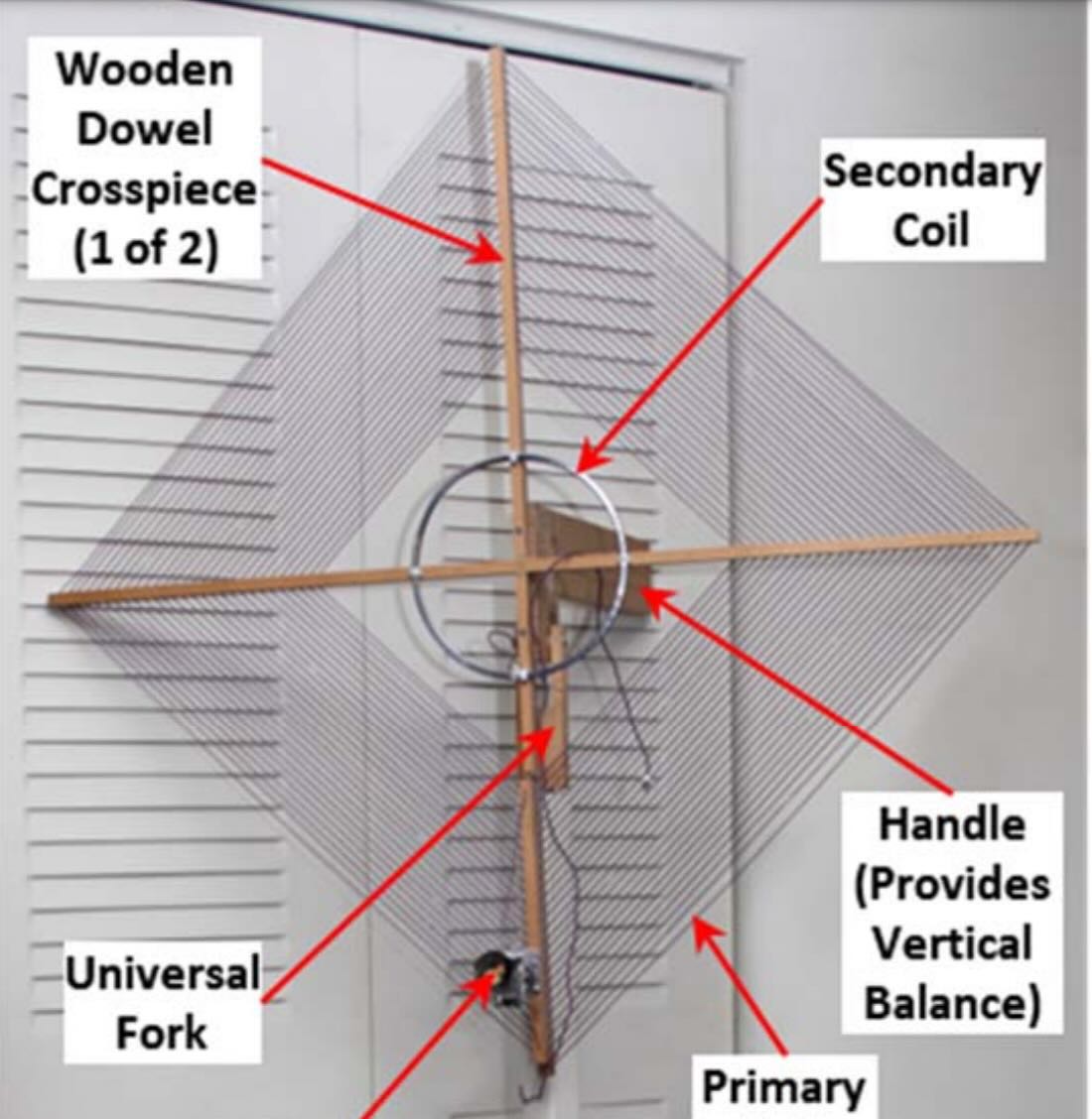
I wonder if something like this 3-axis monster (2M wide) can be built:
https://emcsupplies.com/products/tblla-2m-9-khz-30-mhz-large-loop-antenna
This is the King Kong of all loop antennas.
The typical ferrite rod AM radio has a many turn winding which is resonated with the tuning capacitor and a second winding with a few turns which is acting as a transformer to a non resonant high impedance load ie the input impedance of a frequency down converter or an RF amplifier.
The complication for an external loop is the connecting cable has an impedance of around 50 ohms.
You could connect the loop itself only to a very high impedance load at the antenna. A Metal Oxide Field Effect Transistor with its gate is insulated from the rest of the MOSFET has a very high input impedance when connected as a source follower. The output impedance is low, but output voltage matches the input voltage. https://www.allaboutelectronics.org/mosfet-source-follower-common-drain-amplifier/ for a circuit.` https://course.cutm.ac.in/wp-content/uploads/2020/06/Lect7_AnalogIC.pdf for design formulae.
Another alternative is a FET input op amp in a buffer circuit.https://youtu.be/WSnX7QcBz2E. You will need to connect a pair a 1 MOhm resistor between the + of the power supply and the + amplifier input. Another 1 MOhm resistor between the amplifier input and ground. You will also need a low value capacitor in series between the loop and these resistors to block the DC current going through the loop.
These circuits will keep your Q high as you wish. An Software Designed radio circuit does not have an IF at all so if the Q is too high the high frequency audio will be muffled.
This then requires only the loop itself and the electronics and no wire wound transformer.
Nice score Kevin for this secret document hidden in the bowels of the Internet
RR73
John VE3IPS
Bob & Jock,
Air gap transformers are pretty lossy. Have you tried making a transformer using https://fair-rite.com/product/toroids-5943000601/ as an example. The ferrite core material is suitable for the whole HF band.
Try the same turns ratio.
I have trouble visualizing the geometry of how a ferrite toroid would be connected on a “transformer” this size. Coupling is admittedly very tricky, and I’m not sure lossyness is a consideration here. The situation is different when the primary circuit is at resonance. The magnetic field generated by the primary circuit excites a current in the secondary. Overcoupling by the secondary coil loads the magnetic field. This has the effect of introducing another factor of resistance in the tuned circuit lowering the Q. The object is to find the “sweet spot” where current in the secondary is relatively high and Q of the primary is not badly affected. A few years ago I came across an article that suggested a 1/5th rule, the secondary being 1/5 the diameter of the primary. That might be OK for solenoids, but I’m not sure this would apply to spirals.
To complicate things further, there is a matter of impedance match to the receiver. At HF, the field impedance created by the resonant circuit changes significantly over the frequency range, and the inductance of the secondary coil must be adjusted accordingly to match the receiver impedance. For this I tap the coils on the secondaries.
A shortwave version having the same overall size and general design covering 3400 kHz to 12200 kHz 80 thru 25 meters) is posted at https://swling.com/blog/2021/10/bobs-updated-passive-resonant-transformer-coupled-loop-antenna-for-shortwave/. At the time it was written, this antenna had no vertical displacement; however, I have subsequently modified it to operate on the same tripod with full horizontal and vertical movement. Local noise abatement is exceptionally good.
I’m excited to give this design a try. I haven’t seen the design rationale for a pancake style loop before, and this explains it well, plus gives some ideas for a SW version. Thanks, Jock, and Happy Holidays to all!
Beautiful antenna ……going to build it after the holidays. Nice plans, very well thought out and easy to follow. Thank you so much. 73s Tom WB2FKW
Congratulations to Bob Colegrove for producing an engineering standard construction article along with referenced theory of operation. It complements my posting of https://swling.com/blog/2024/11/bbc-rd-how-to-test-a-loop-antenna/
Very nicely done article. The clear schematics and carefully worded instructions are appreciated. Too many articles appear with no carefully drawn schematics. Based on these notes I can easily modify my current PVC 1 inch pipe-based MW loop assembly and modify my rather clunky coupling procedures. I use an active loop for SWL’ing and appreciate the ability to reject some interferers and peak stations in which I am interested.
KA6GEH
Nice work Jock.
If I had time and patience these days I would build one.
I have built 2 large loops based on the design of Shawn Axelrod. One wood, the other with PVC.
Any loop 3 feet across and larger always works very well.