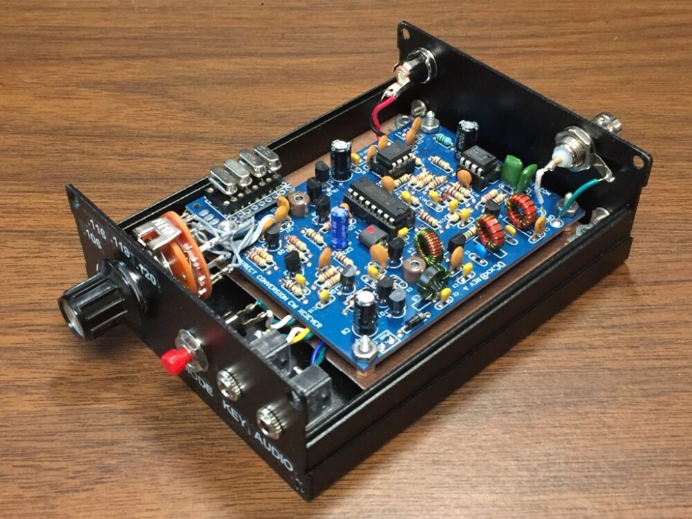
 Many thanks to SWLing Post contributor, Steve (KZ4TN), who shared the following guest post originally on QRPer.com, but I’ve posted it here as well because I’m sure it’ll resonate with those of us who love building kits!:
DC30B QRP Transceiver Project
by Steve Allen, KZ4TN
I wanted to build a lightweight backpackable transceiver I could take hiking and camping. I chose the 30 meter band as it is specific to CW and the digital modes. I am also in the process of building Dave Benson’s (K1SWL) Phaser Digital Mode QRP Transceiver kit for the 30 meter band. Also, a 30 meter antenna is a bit smaller than one for 40 meters and the band is open most anytime of the day.
I sourced the DC30B transceiver kit, designed by Steve Weber KD1JV, from Pacific Antennas, http://www.qrpkits.com. It appears that they are now (10-11-20) only offering the kit for the 40 meter band. The following information can be used for the assembly of most any kit that lacks an enclosure.
Lately I have been finding extruded aluminum enclosures on Amazon.com and eBay.com. They come in many sizes and configurations. I like to use the versions with the split case which allows you to access the internal enclosure with the front and rear panels attached to the lower half of the enclosure. Most of these enclosures have a slot cut into the sides that allow a PCB to slide into the slots keeping it above the bottom of the enclosure without having to use standoffs. The one requirement for assembly is that the PCB needs to be attached to either the front or rear panel to hold it in place.
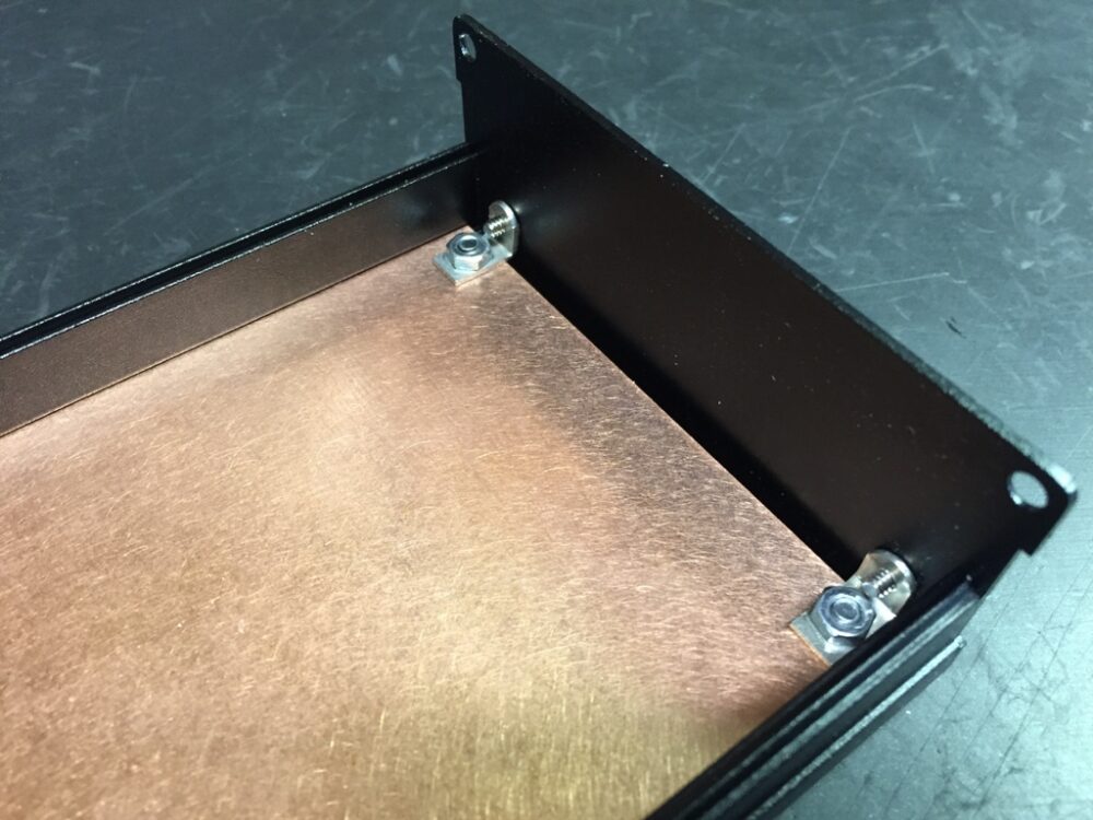
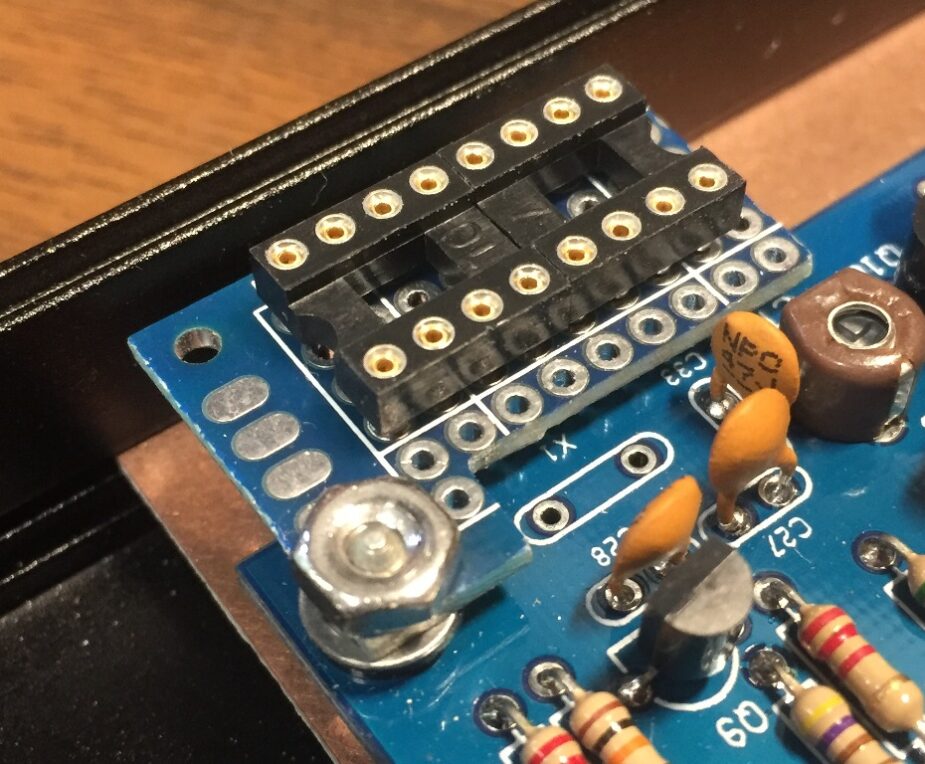
As the enclosure is anodized, I didn’t want to rely on the enclosure for common ground. I used a piece of copper clad board that I cut to fit the slot width of the enclosure and attached it to the back panel. I was then able to mount the transceiver PCB to the copper clad board with standoffs. This basic platform of the enclosure with the copper clad PCB provides a good foundation for any number of projects. All you have to do is mount the wired PCB on the board, install the components on the front and rear panel, then wire it up.
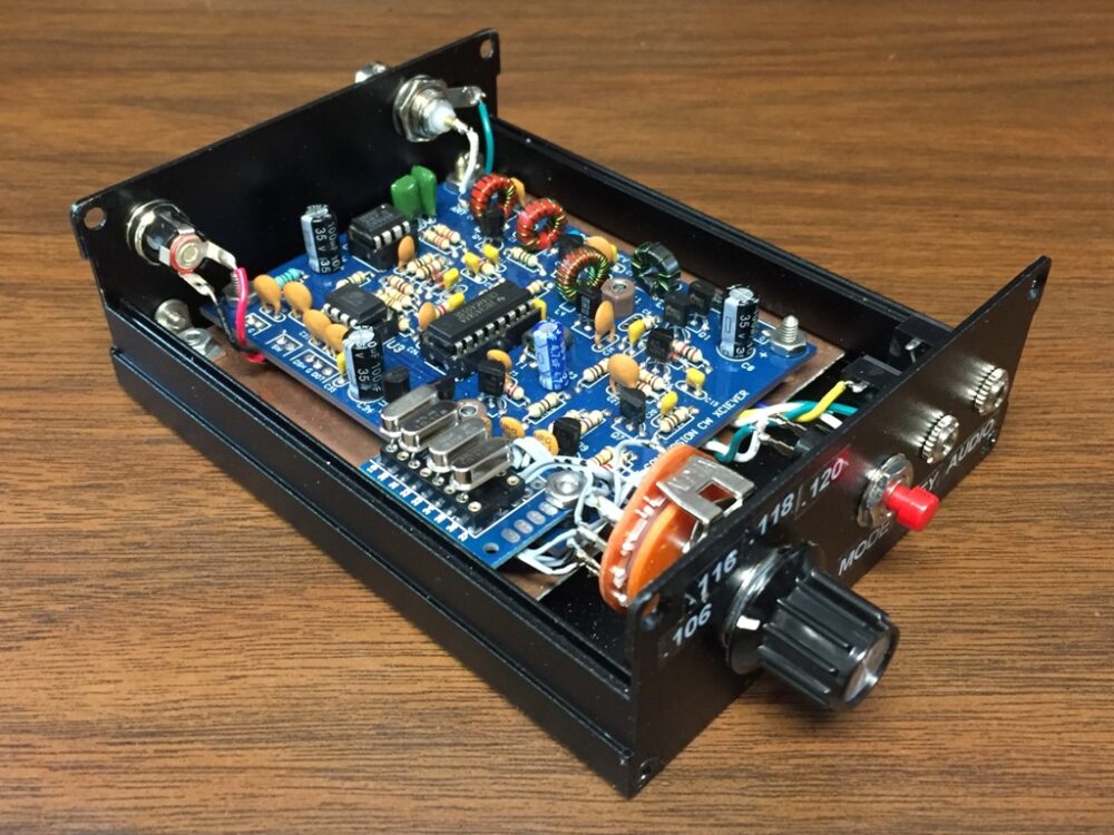
I wanted to have the choice of a few frequencies to operate on so I searched eBay for 30 meter crystals and found a source for 4 different popular frequencies. I installed a rotary switch on the front panel and added a small auxiliary PCB with two, 4 pin machined IC sockets. This allowed me to plug the crystals into the sockets. I wired the bottom of the socket PCB first using wire pairs stripped from computer ribbon cable leaving extra length. I marked the wires with dots to indicate which sockets each wire pair went to so I could solder them onto the rotary switch in the correct order. It was tight but I always work with optical magnification so I can see exactly what I’m doing. I have used this crystal switching method in the past with good success.
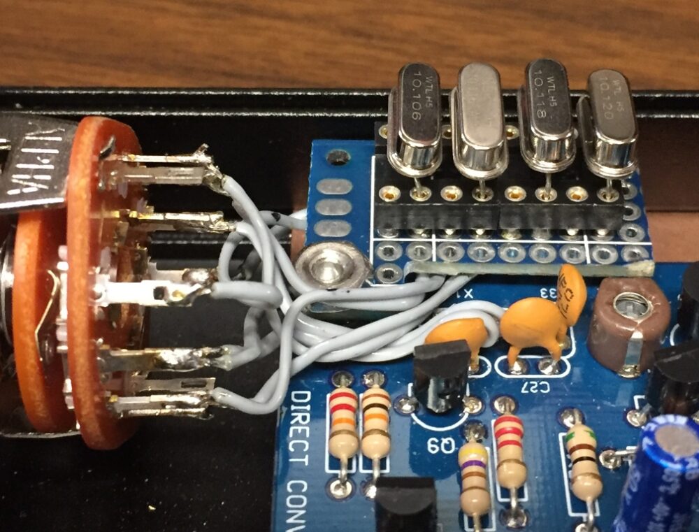 The rest of the assembly was straight forward. I find that most kits are well designed and documented, and if you take your time and follow the directions carefully all should go well. The two most common speed bumps seem to be soldering in the wrong component or bad soldering technique. I double check all component values and placements prior to soldering, and I always use optical magnification while working. I inspect each solder joint and look for good flow through in the plated through holes, and make sure there are no solder bridges.
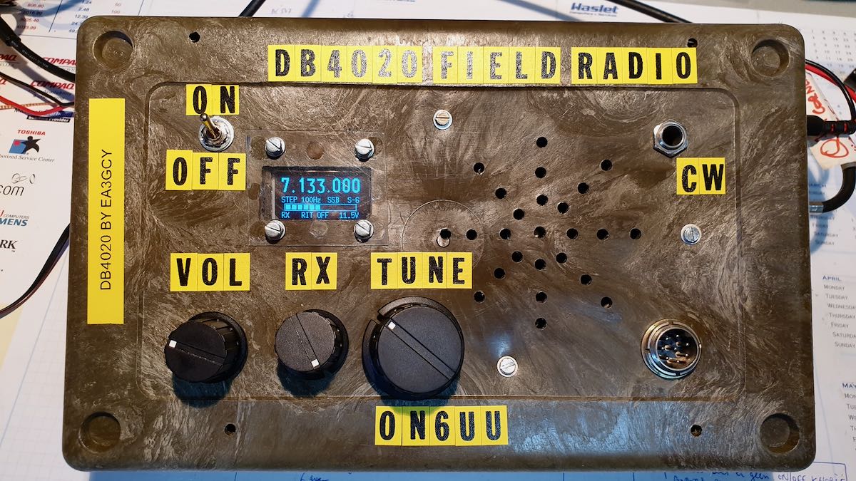
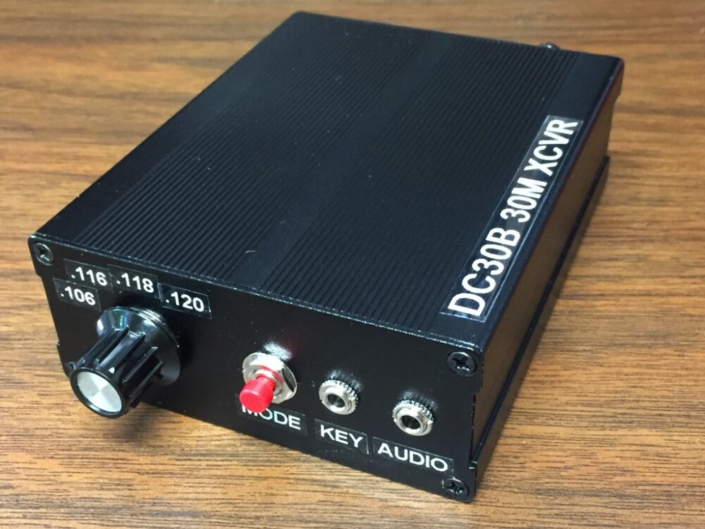 The finished product. I bought a Dymo label maker and it works very well for projects like this. I love using these enclosures and they are a leap forward from the old folded aluminum clam shells I used in the past. I could stand on this without causing any damage. Power out is 1-3 watts depending on the DC power in. The receiver is sensitive and the ability to choose from four frequencies is a real plus.
73 de KZ4TN
Steve Allen
Elizabethton, TN
Gorgeous work there, Steve! Thank you for sharing!

