Many thanks to SWLing Post contributor Steve Allen (KZ4TN), who shares the following guest post:
SDR Signal Enhancer
by Steve Allen
I came across this HF Signal Enhancer for SDR on the RTL-SDR.com website. It was designed and built by Peter Parker, VK3YE from Melbourne, Australia. Below is the link to the video of the signal enhancer in action using an RTL-SDR V4 Software Designed Radio;
www.youtube.com/watch?v=W6OXc_wZTXU
It was very easy to see and listen to the improvement to the signal reception the signal enhancer made. Having been a life-long shortwave listener and current SDR user, I had to build one.
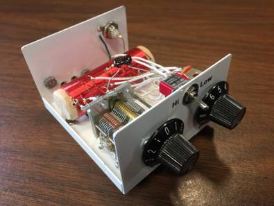
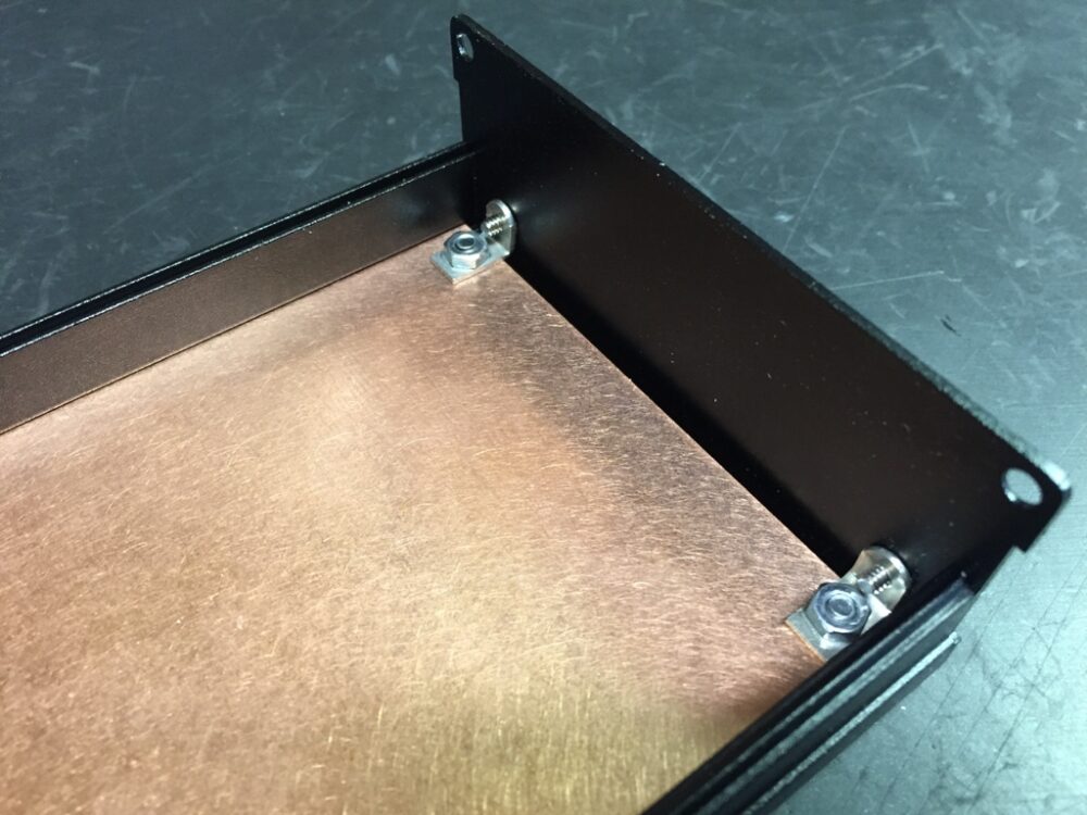
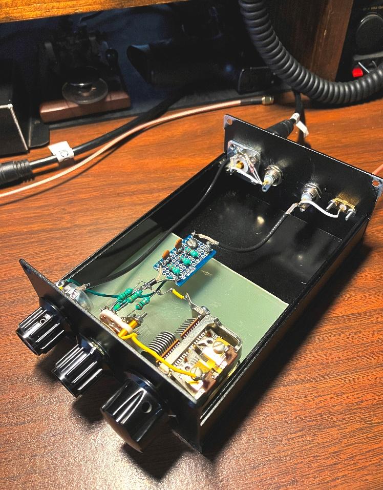
I did a screen capture of the schematic, re-drew it using MS Word, and built the bill of materials. In Peter’s original design he included a T-R relay so you could use the SDR along with a transmitter, which I opted to leave out. I had the passive components in my “junk box” but had to source the enclosure, controls, and antenna connectors. I have used these clam shell extruded enclosures with previous projects and love the build quality and the fact that they incorporate a slot in the sides which let me insert a sheet of PCB material on which I can do the assembly.
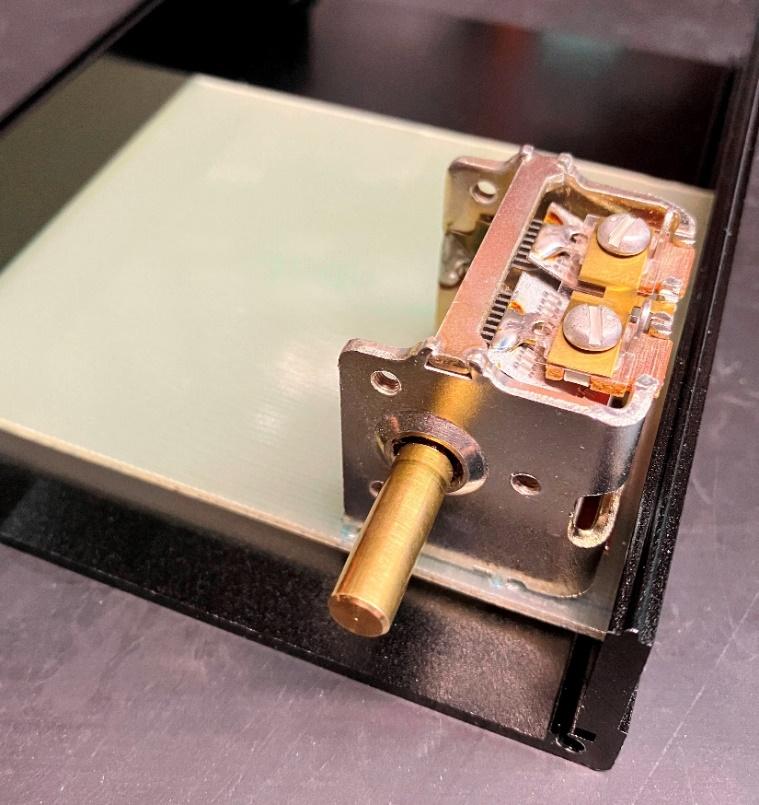
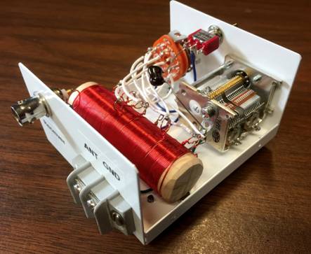
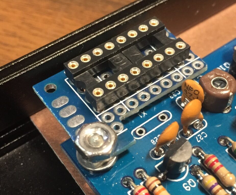
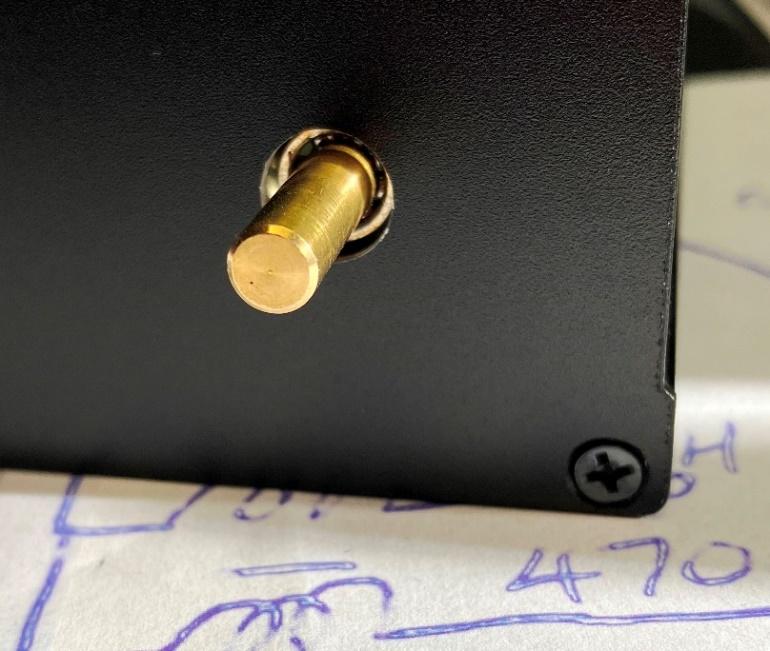
Referring to the schematic drawing in Peter’s video, you can see that the variable capacitor “floats” above ground, which is not the usual application for these devices. To do that I mounted the vari-cap on a piece of non-plated PCB material that I cut to the width of the enclosure and it fit nicely within the slot. The vari-cap had three pins on the side of the frame that allowed me to force fit it into three holes I drilled in the PCB material. I was very careful to drill the holes undersize and then slowly open them up until the vari-cap press fit on to the board. For good measure I ran UV curing adhesive down into each hole, letting it flow all the way through before I set it with a UV light source.
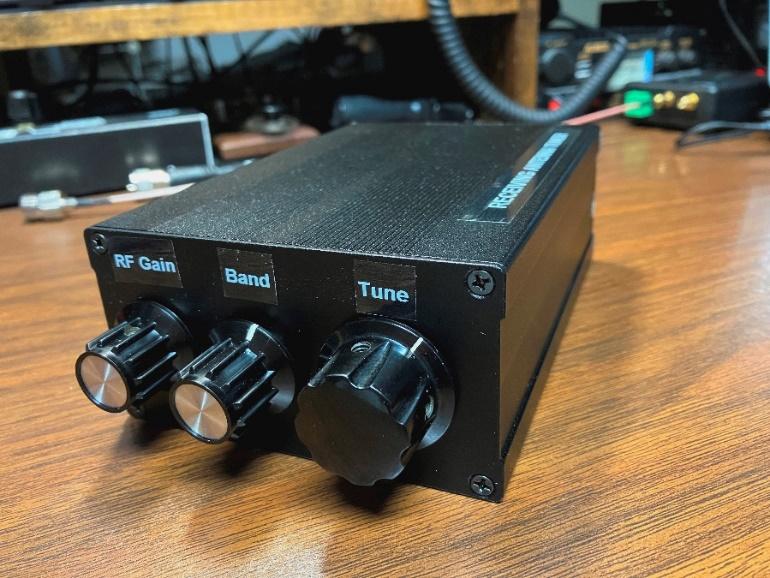
 I then drilled an oversized hole in the front panel for the vari-cap shaft to pass through.
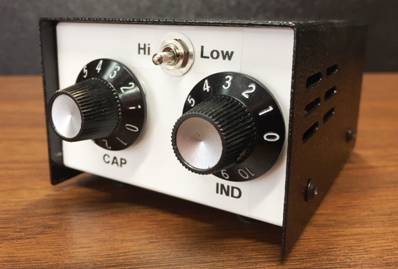
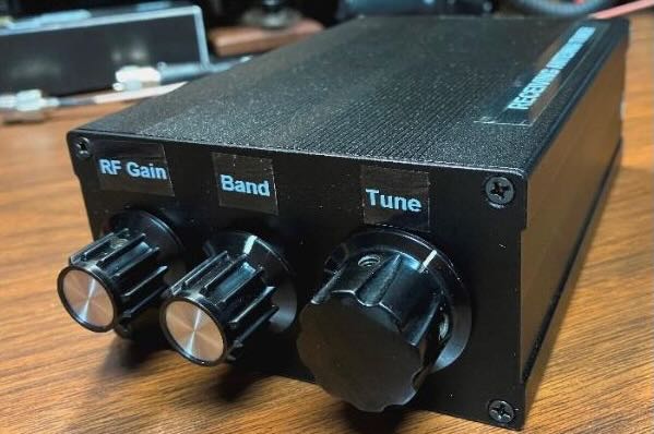
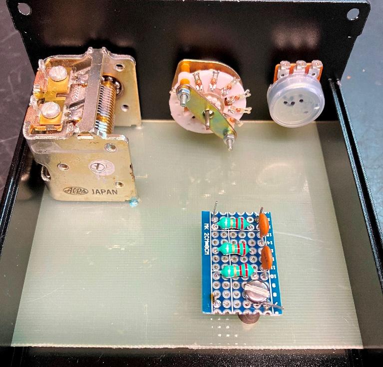
 I then mounted the RF gain and band switch. The next step was the assembly of the AM broadcast filter. As SDRs can be overpowered by local AM radio stations Peter choose to include an internal band pass filter that is configured for around 3.5 MHz. The intent of this filter is to attenuate the signals below 3.5 MHz. Strong AM stations will still be heard but there is much less chance of them bleeding through on the higher frequencies.
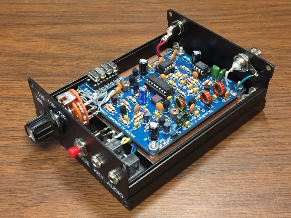
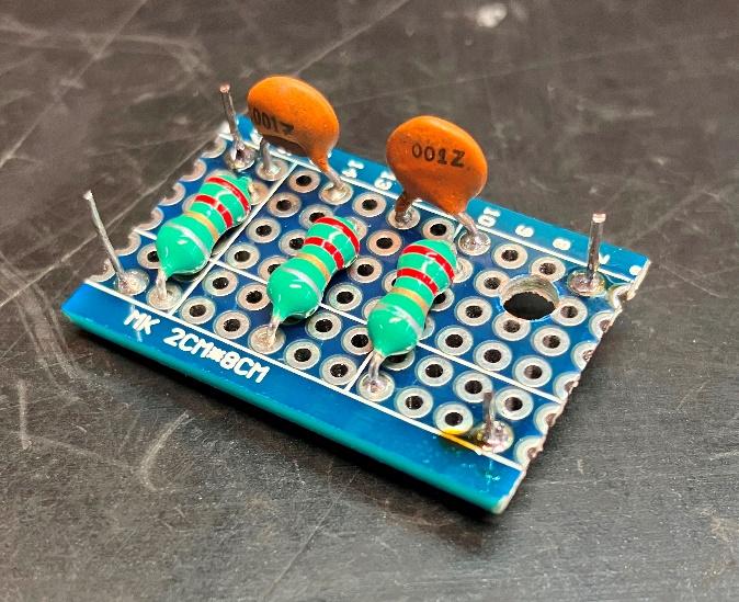 I assembled the filter on a piece of perf board and connected the component leads on the bottom. I passed leads back up through the perf board for the signal path and ground. I mounted it on the main board with a standoff.
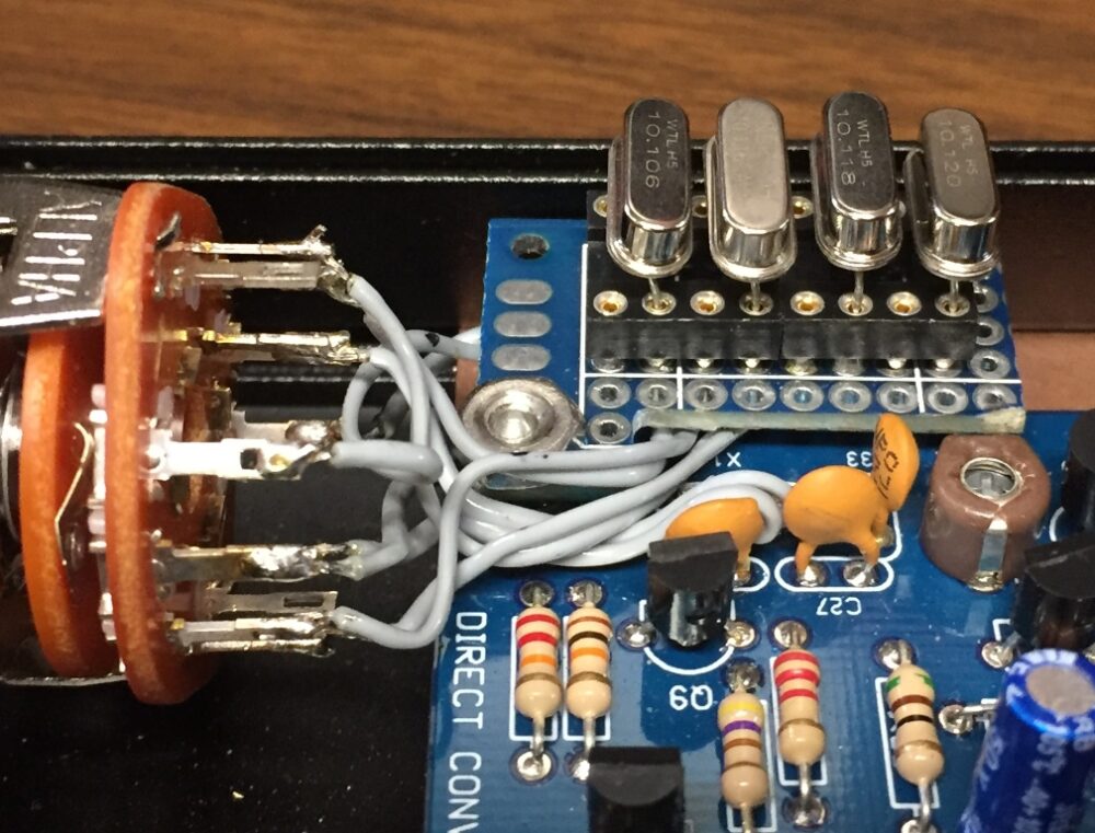
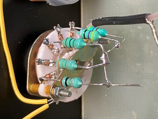
 The next step was the wiring of the inductors to the rotary switch. Simple, and I tied them to the vari-cap frame.
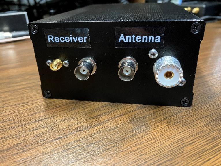
 For the back panel I chose an SO-239 and a BNC for the antenna input, and for the radio connection an SMA and another BNC. I sanded off the coating on the enclosure at the antenna mounts as well as the four corners where the back panel screws into the top and bottom of the clam shell enclosure to provide good grounding of the enclosure. I wired the 1N4148 diodes on the antenna connectors, and attached the RG-174 coax. As Peter suggested, I grounded the long (relatively speaking) runs to and from the back panel with coax and grounded it at the back panel.
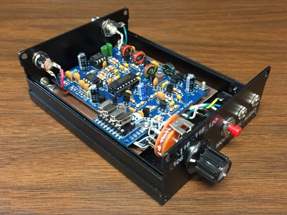
The last step was to apply a bit of epoxy adhesive to the fiberglass board and the slot it runs in to hold it in place. Once the epoxy set, I did the final wiring of the front and rear panel components. You can see how I sanded the corners of the back panel in the above photo.
 I connected it to my inverted L antenna and an SDR Play RSP2 and gave it a test run. I like the fact that I can visually see the changes to the signal strength on the SDR software as well as audibly. It makes a noticeable improvement to the reception.
Thank you Peter. I enjoyed the build.
Steve Allen, KZ4TN