
 Many thanks to SWLing Post contributor, David Day (N1DAY), for sharing the following guest post:
Crystal Radios – Construction, Listening, and Contesting
By David Day – N1DAY
The date was November 2, 1920 and the world was about to change forever when radio station KDKA out of Pittsburgh PA made its first broadcast of election results from the 1920 presidential election. For the first time in history people knew who won the election before reading about it the next day in the newspaper. Radio had arrived!
However, hearing the election results was not as easy as powering up an AM radio receiver because radio electron tubes had only been invented a few years earlier and they were still too expensive for most people to afford in a radio set. After KDKA’s historic broadcast, large 50,000 watt stations began popping up in all major cities around the world. Even though a tube-driven radio was not yet commonplace, many people listened to these stations on their crystal radios. The frenzy around radio in the 1920’s was not unlike the excitement around cell phones and the internet today. If you didn’t have one, you were simply living in the past.
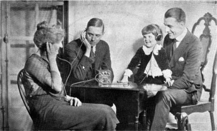
A family listening to a crystal radio in the 1920’s
Fortunately, in the early 1920’s the crystal radio had been around for a while and it was easy to make or purchase a completed set on a limited budget. The beauty of the radio was that it was a passive device needing no power source other than the radio station’s broadcast that was received by a good antenna about 50 feet long and 15 or so feet above the ground. Crystal radios derived their name from use of galena crystals as detectors.
Galena is chemically Lead Sulphide and deposits of this mineral are quite common throughout the world. If touched lightly with a very thin wire , known as a cat’s whisker, at just the right spot on the crystal surface, galena will act just like a diode allowing DC current to pass through it. This providing a means of demodulating an AM radio signal. Having the ability to demodulate a radio signal without a power source was a big deal, especially in rural America, where access to electricity was not yet commonplace.
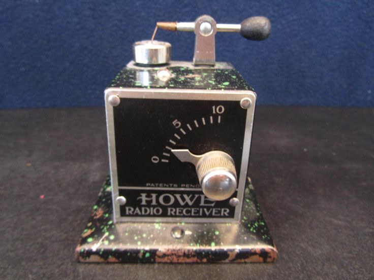
A galena crystal and ‘cat’s whisker’ detector on a 1920’s Howe receiver
By the late 1920’s, electron tube technology and manufacturing capabilities for radio components had advanced to the point where tube radios would outperform crystal sets at a price that many could afford. At the same time, batteries and electronic starters were becoming the norm in transportation vehicles. As a result, people started to have access to tube radios along with a convenient way to power them.
The competition to sell radios was fierce and companies like RCA, Atwater-Kent, Zenith, Westinghouse, Sears, and Montgomery Ward began to produce a variety of inexpensive tube radios. One only needed to park their car next to an open window, and hook their tube radio up to the car’s battery to listen to a Sunday afternoon baseball game without the fading and interference common to crystal radio sets.
Consequently, crystal radios became relegated to the status of a child’s toy by the 1930’s. From that time, crystal radios purchased in kit form or made from found parts were targeted to younger individuals as an introduction to radio electronics. For many years, the Boy Scouts crystal radio kit was a common training tool in that organization. Even today, a variety of crystal radios, both completed, and in kit form can be purchased through a variety of web-based retailers such as Amazon, eBay, and Etsy. eBay, is an especially good source for collectors of vintage crystal radios as well.

The ’Dunwoody’ is a good performing crystal radio kit available through several on-line retailers.
During the period of about 1910-1925, many individuals did a lot of experimentation with crystal radio circuitry attempting to improve their performance. That body of knowledge was well documented in early home-electronics magazines which covered new circuitry ideas and component developments in great detail.
Most of that knowledge has been preserved on a variety of websites. Like many other early technologies that were superseded by new discoveries, small groups of individuals, passionate about the nostalgia and pleasure of crystal radio have kept the technology alive and continue to improve upon today by incorporating different concepts and materials into new radio designs.
Crystal radios that were originally intended to receive AM broadcasts over less than 100 miles can now receive 5-10 kilowatt AM stations from several thousand miles away as a result of this experimentation. With attention to exacting detail in component construction, a number of individuals use their crystal radios to tune into shortwave broadcast stations as well.
In the early 2000’s the Birmingham Crystal Radio Group began an annual contest for operators and designers to foster the development and incorporation of new concepts into crystal radio designs. Contestants earned scoring points based upon number of stations received as well as distance of the AM transmitter from the contestant’s listening location. Much of the work and developments from this group is documented at their website, crystalradio.us.
The key restriction in their events was that the radio used in the contest could not have a power source other than that received from the transmitting station. These contests provided an incentive for crystal radio enthusiasts to continue experimenting with new circuit designs that led to new performance improvements.
One of the more well known radios to emerge from this period was Mike Tuggle’s Lyonodyne crystal set. Mike operated out of Hawaii, and routinely received AM broadcasts from mainland United States and other foreign countries. The success of his radio was the result of a new tuning design, use of only the highest quality components, and meticulous attention to construction details. Complete information on the Lyonodyne can be found at the web address https://www.crystalradio.net/crystalsets/lyonodyne/index.html.

Mike Tuggle’s Lynodyne
Why the ‘dyne’ designation in the radio name? That is uncertain and is suspected to be one of those whimsical things that inventors sometimes do. It caught hold, and today we have a lot of crystal radios with names like the Hobbydyne, Vertodyne, Baodyodyne, Frankendyne, and Toroidyne. Many of these sets can be found at Crystalradio.net which is a must bookmark site for anyone interested in crystal radio design and operation.
Joseph Watson’s VertoDyne – a solid contender in the 2022 contest.
So, how does a crystal radio work? In reality, the crystal radio is the most fundamental form of radio circuitry and employs the simple inductor-capacitor resonant circuit.
Below is the schematic for the basic crystal radio. With a spool of wire, cardboard tube, a 20 cent 1N34A diode, a capacitor (fixed or variable of about 200-300 pF) and an old-style transistor radio earpiece, a functional radio can be built in about an hour.
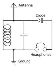
Basic Crystal Radio Circuit
In the earliest crystal radios, tuning was accomplished by shorting out part of the inductor loop (repeating loops in the above diagram). By changing the point at which the shorting occurred, all undesired signal energy would be directed to ground, and only the signal of interest would be sent to the diode where the AC portion of the transmitting station’s signal would be stripped from the DC component which then, through a set of high impedance headphones (or earpiece), would allow the modulation to be heard as a voice or music.
This is how the Boy Scouts Crystal Receiver kit worked. By sliding a metallic arm across the inductor coil, it could shorted out at different points with the result being rudimentary tuning of stations at various frequencies.
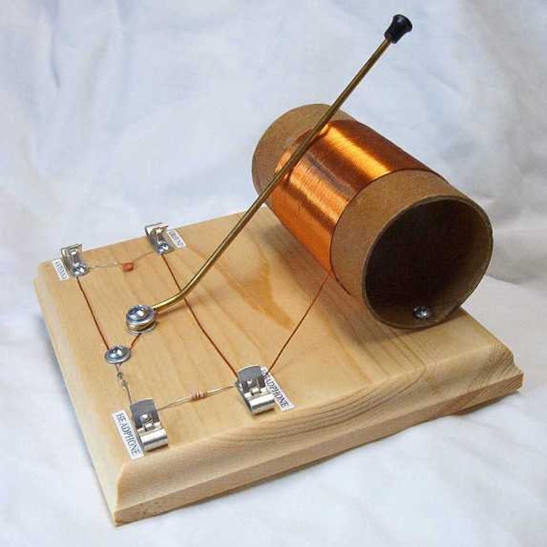
Basic crystal radio
As can be expected, tuning and reception was not very precise with the basic crystal radio, and this problem is what kicked off a great deal of development prior to introduction of the electron tube. Hundreds of crystal radio circuits were designed to improve tuning selectivity without loss of sensitivity. A lot of this work centered around the way the crystal radio’s detector components were coupled to its tuning components to achieve the best balance between selectivity and sensitivity. It involved experimentation with inductor coil designs, impedance matching between radio components, signal loss mitigation, grounding methods, antenna design, etc. To this day, a lot of crystal radio experimentation still centers around ways to improve radio selectivity without loss of sensitivity.
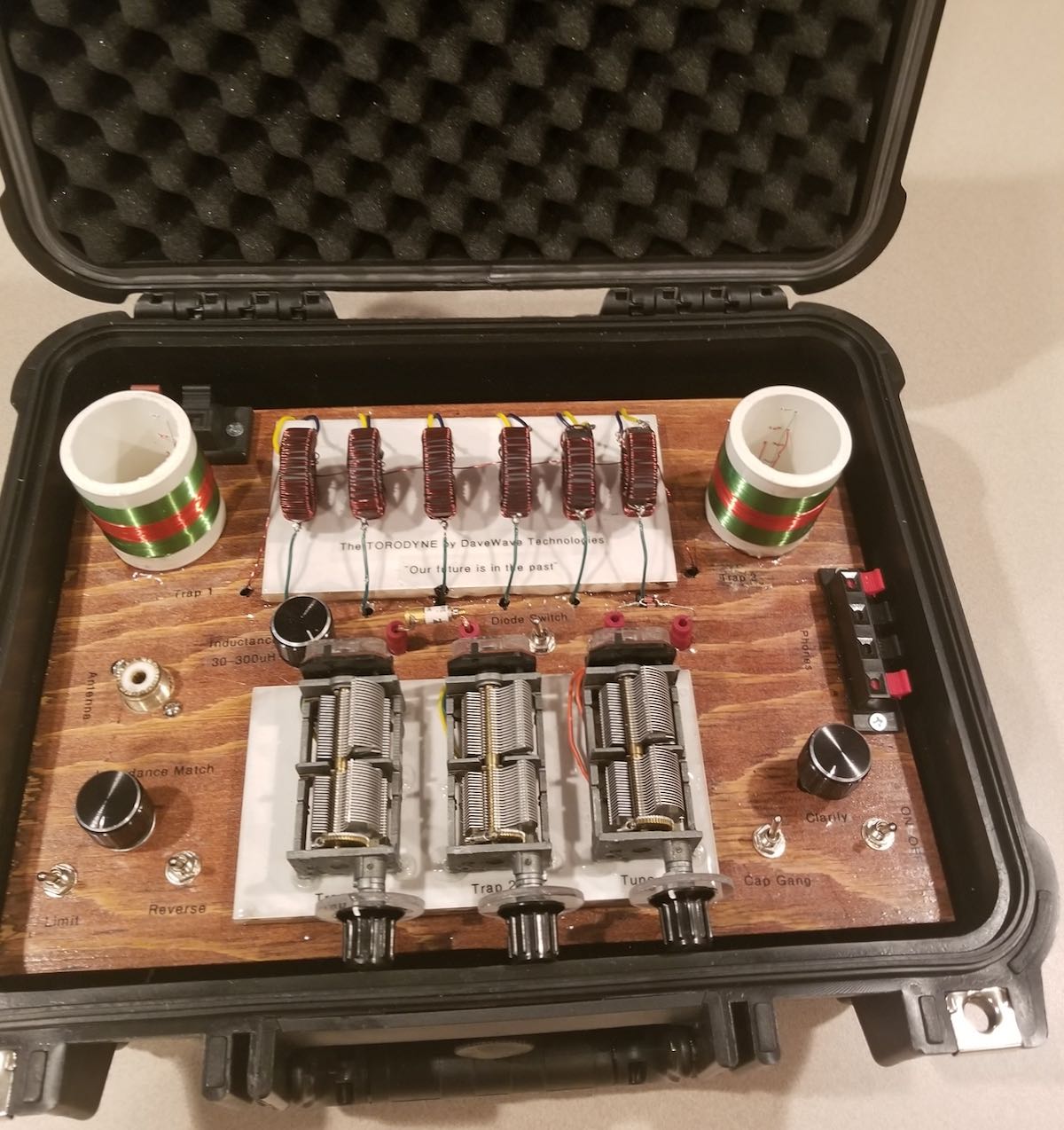
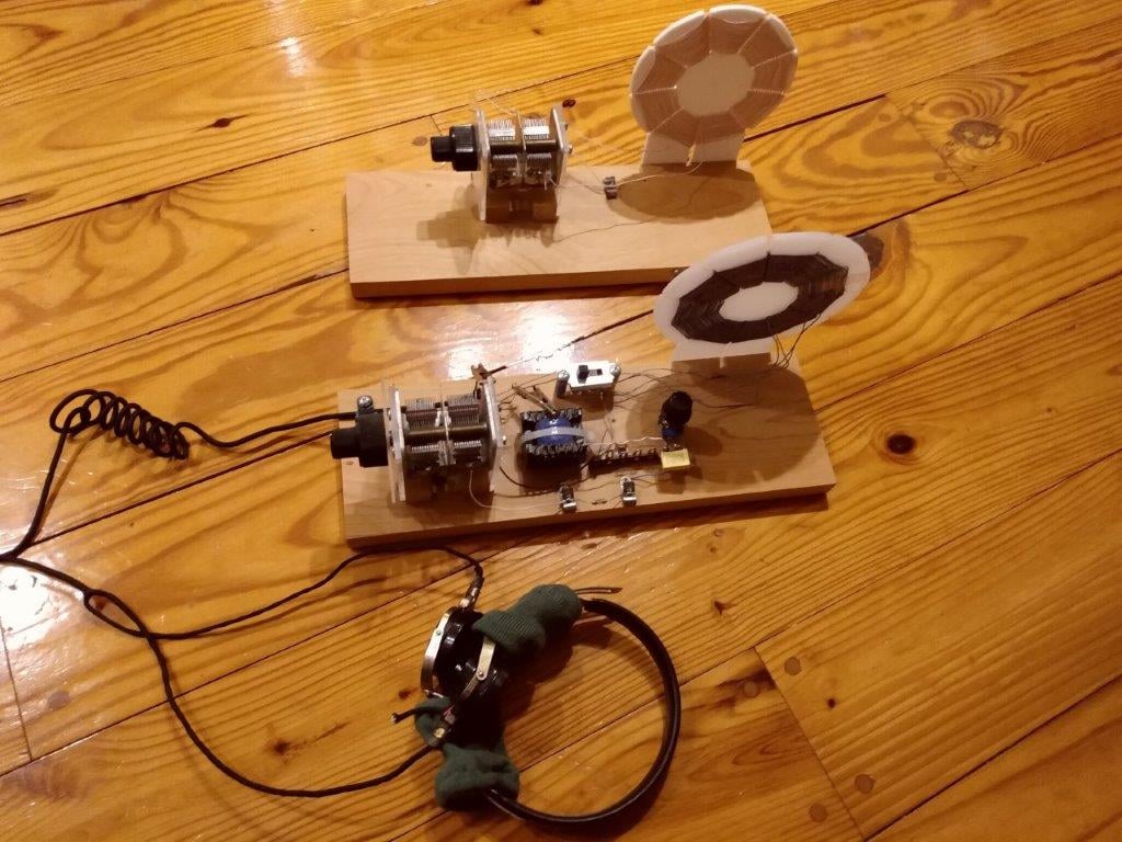
For example, the Toroidyne crystal radio which placed 2nd in the 2022 DX contest departed from traditional radio crystal radio designs to achieve improved selectivity without loss of sensitivity.
It utilized an antenna impedance matching transformer positioned outside of the inductor coil to lessen reliance on the inductor coil for both tuning and impedance matching. This feature was then coupled to the detector circuit through a series of toroid wound inductor coils of various sizes that were coupled through a fixed -turn coil size attached to the antenna. The goal was to achieve optimal impedance matching between the tuning and detector circuits so that sensitivity could be improved without significant loss in selectivity.
The concept was proven in the 2022 DX contest. With only 12 hours of operation, 87 unique AM broadcast stations were identified at the Torodyne’s operating location in Western North Carolina. This included four Cuban stations at a distance of approximately 1,100 miles, a station in Puerto Rico at 1,500 miles, and one station in Tijuana, Mexico at 2,100 miles.

The Toroidyne
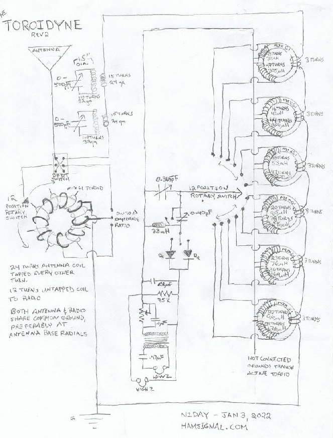
The Toroidyne schematic demonstrates how crystal radios have evolved over the years to improve performance.
Since the 2022 contest, it was discovered that a Toroid-based inductor design could be further improved by careful attention to Toroid selection based on permeability characteristics. This provides a good example of the possibility for continual design improvements in a method of radio reception that is now over 130 years old. Other areas for potential improvement of crystal radio technology are in the use of FET’s in place of traditional germanium and silicone-based diodes, variable capacitor design, and impedance matching strategies to maximize broadcasts heard through a wide variety of headphones and piezo sound devices.
With crystal radios, tuning is generally broad, and plagued by interference from local stations that tend to interfere the whole way across that band. Resolving that issue requires the use of notch filters that have remained almost unchanged since the earliest days of radio. By running an antenna wire through a coil of approximately 20 turns of wire that is would over approximately 110 turns of smaller diameter wire on a 1.5 – 2” coil and attaching a variable capacitor to each end of the smaller wire, it is possible to notch out and dissipate offending stations and allow weaker stations throughout the AM band to be heard.
Steve McDonald of British Columbia, Canada replaced the traditional air coil trap method with a series of coils wrapped around several low permeability toroids. His situation was unique in the contest as he had to deal with nulling out 15 very loud stations across the AM band that interfered with his reception. The modification worked well and Steve ended up logging 92 stations for a 3rd place finish with several stations in the 1,500 mile range and one exceeding 2,000 miles by utilizing several of his traps in series.
The Bucher Notch Filter was a component used in early Marconi radios and remains in use in crystal radios to this day as an effective tool in silencing interfering station signals.
Steve McDonald’s DX crystal radio. Note the elevation and insulation of components from the wooden table. Proximity to surfaces like wood that contain moisture can quickly reduce power transferred through the various stages of a crystal radio.
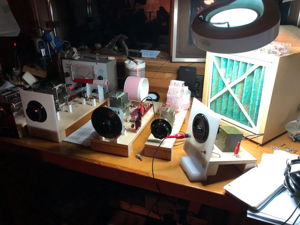
The exciting part of crystal radio contesting is that it does not necessarily require a radio with all of the bells and whistles to turn in a good performance. Doug Allen of Inman, South Carolina competed in both the Hobby and Open classes of the 2022 contest using a vintage Miller crystal radio that was commercially available in the mid 1950’s along with a single circuit hobby class radio of his own design. With the strategic use of directional antennas and some good pre-contest planning, Doug turned in a total of 153 stations in the open class and 151 stations in the hobby class for the first place finish in both competition classes. This demonstrated that anyone, regardless of level of radio construction skill, can participate and effectively compete in future crystal radio competitions.
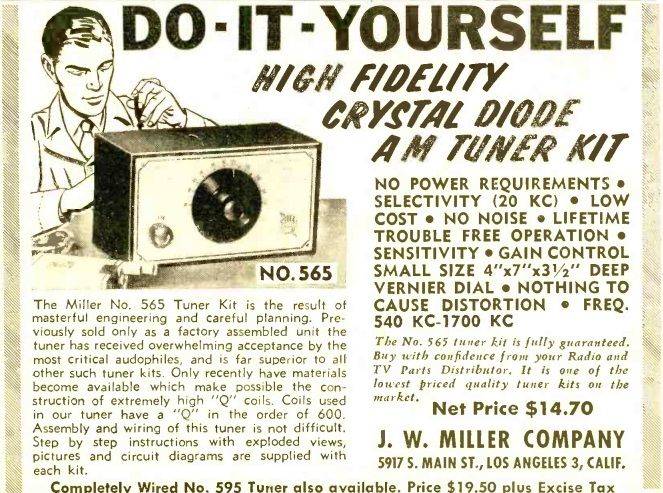
Advertisement for the 1950’s Miller Crystal Radio – available both as a complete radio and as a kit.
Dan Renkel’s homebrew radio, operated in central Pennsylvania finished high in the scoring in the recent contest with a beautiful example of coupling coils.
With the growing popularity of Facebook, crystal radio enthusiasts from around the world participate in groups such as the Crystal Radio DX Contest group, Crystal Set Radio Group (2 groups with the same name), Home Built Radios group, and Radio Experimental Mundial (South America) . Over 8,000 individuals spanning the globe routinely contribute to these groups demonstrating that interest in crystal radio building and listening is still alive and well.
Visiting one or more of these groups is a good place to start in learning about recent developments in crystal radio and ways that individual participants are currently evolving this century old technology. The listed Facebook pages are also good places to visit periodically to find out when future contests and celebrations of crystal radio listening will occur.
For more information on Crystal radios, schematics, construction and operation details, please visit the following web sites:
- http://makearadio.com
- http://peeblesoriginals.com
- http://xtalman.com
- https://nutsandvolts.com/magazine/article/remembering-the-crystal-radio
- https://crystalradio.net
- http://crystalradio.us
- https://hamsignal.com
- Books: Crystal Clear Volumes 1 and 2 by Maurice L. Sievers (SWling Post Amazing affiliate link)
Thank you so very much for this excellent article, David! I love how you’ve explored the roots and history of crystal radio while also demonstrating that design innovations can make these true DX machines. Phenomenal!
Fro more info about David (N1DAY) and his many radio experiments, check out HamSignal.com.
I will just add a link, to the ones you listed
http://theradioboard.com/rb/viewforum.php?f=2&sid=76267c849705718bf03347c0bbef416c
😀
Fantastic article, thanks so much for posting this! The contest results are incredible. I doubt if most of us could do as well with a commercial superhet.
I built a little crystal radio kit as a kid. My father helped me and, as I recall, we built it on a cigar box. When I read about the foxhole radio — probably in Popular Electronics magazine — I had to make one. It used a piece of pencil lead and a blued razor blade as the detector. My grandfather was a TV repairman, and when I showed him my little foxhole radio he thought I was a genius!
Great article. Brings me back to my first crystal “set” that my father gave me. I was probably 9-10 and “hooked” on radio thereafter.
J
Thanks for pointing out the regen set which was labeled as a crystal set. I removed this so there’d be no confusion. I think the wrong photo was picked for the caption. Thank you!
Wonderful article indeed! I’ve heard that some hardcore enthusiasts still work on improving crystal radios before, but I had no idea how impressive the results of this work would be. I couldn’t help comparing the mileage with the current DX Central MW challenge results and I must say I’m floored that crystal radios can more than compete with that!
Making the most of the oldest and initial radio design with its manageable/different complexity sounds like a very compelling alternative/counterpart to hunting for the most sophisticated radios, that they do not even need batteries and – as DIY projects with very few parts – use very little other resources gives them an unexpectedly modern touch, too! 🙂
I had no idea that there’s all this design work still going on with crystal radios. What’s more, it’s actually getting us somewhere.
Then, having worked with genetic algorithms and knowing the weird stuff they can produce, I had to go digging around on the web. Not really a surprise, someone’s applied these methods to crystal radio design back in 2008: https://www.researchgate.net/publication/3419023_An_AM_Radio_Receiver_Designed_With_a_Genetic_Algorithm_Based_on_a_Bacterial_Conjugation_Genetic_Operator
I was a little disappointed though that the paper’s more about the GA algorithm they developed and the radio circuit was just a convenient test case. Still, that’s something.
And now Thomas Witherspoon has to translate
Récepteur à cristal from the large Wikipedia entry for us. 😉
Ha Ha!
The crystal set, and all superhetrodyne receivers all use a diode for demodulation of the AM. So all AM stations have been transmitting the carrier to cause a DC bias on this diode to minimise severe distortion.
The carrier is between 100 – 67 % of the transmitted power and it carries no sound signal, that is in the sidebands.
Pure digital and hybrid HDradio both contain the carrier. In Pure digital the carrier is around 90 % of the transmitted power and contains no data.
This has been going on since 1920, now Software Designed Receivers receiving DRM, and DAB+ do not use a carrier, but low powered pilot tones to control the recreation of the carrier required for demodulation. They do not use a diode for demodulation but just multiply the input signal by a reconstituted carrier to produce good quality sound.
In 1914, Howard Armstrong got his patent for the regenerative receiver. In 1919, he got his patent for the superheterodyne receiver. In 1922, he got his patent for the superregenerative receiver.
Cost meant the crystal radio kept going. Especially with local broadcasts, you could live with the limitations.
Don’t forget that in the early days, there was ship to shore, military, and amateur. Hams played with broadcasting when they realized there were more people with receivers than transmitters. Commercial broadcasting was the first time there was something aimed at listeners
Probably the photo of the Aeriola regenerative set (I own one) probably wasn’t picked by the author. At least I hope not.
Reference the Aeriola, the label is Westinghouse because of a cross licensing agreement between Westinghouse and RCA. So they were manufactured by Westinghouse and distributed by RCA.
Oops, the set that was pictured above as an early crystal set is actually an RCA Aeriola Sr, a regen receiver with one WD-11 tube. Photo probably should have been an RCA Aeriola Jr. crystal receiver.