Monthly Archives: May 2022

How Giuseppe protects his Icom IC-705 during travels

Many thanks to SWLing Post contributor, Giuseppe Morlè (IZ0GZW), who writes:

Dear Thomas and Friends,

Giuseppe Morlè (IZ0GZW) here from Formia, central Italy.

This my latest video is about everything I have done to protect and transport my Icom IC-705.

I bought an aluminum case, light and very resistant with everything one needs inside to be able to use the IC-705.

    • 2 power banks, one of which is solar-charged to be able to recharge the battery while in operation
    • 2 wire antennas: a dipole type with BNC / banana socket with 10 meters of cable per arm and a 20 meter row, monopole, to be used in reception as you saw during the DXpedition to the Island of Ponza
    • I also bought the Mydel protective “cage” with antenna attachment on the front and PVC protection of the display

Given the high cost of this little jewel, it is advisable to take all precautions for its safety during transport and use.

Click here to view on YouTube.

I hope I made you happy …
Thank you all,
73. Giuseppe Morlè iz0gzw.

This is great, Giuseppe! Like you, I’ve taken extra measures to protect my Icom IC-705 as well. Your kit looks comprehensive–I love the fact that pretty much everything you need is inside. 

Thank you again. We always enjoy your posts from beautiful Italy. Ciao!

Spread the radio love

SPECIAL BULLETIN: WBCQ’S RADIO ANGELA MOVES TO 5130 KHZ

From Bill Tilford, curator of WBCQ’s Radio Angela program block:

Effective immediately, WBCQ’s Radio Angela block of programs is moving from 4790 kHz to 5130 kHz.  The actual schedule is not changing, only the frequency.   This will get the broadcasts away from the existing CODAR and other major interference issues while hopefully maintaining a similar coverage area with a better listening experience for most people.
Reception reports may be sent to [email protected]

Spread the radio love

Kostas pairs his Collins 51S-1 with a Heathkit SB-620 bandscope

Many thanks to SWLing Post contributor, Kostas (SV3ORA), for sharing the following guest post which originally appeared on his radio website:


Collins 51S-1 band scope using a Heathkit SB-620

by Kostas (SV3ORA)

The purpose of this project, is to connect a Collins 51S-1 receiver with a Heathkit SB-620 “scanalyzer”, so as to give the 51S-1 band scope capability. Right into the schematic presented below, a slight modification is needed to the 51S-1. I usually do not do modifications to old equipment unless absolutely needed and even when I do so, I take care for them to be easily undone and to modify them as little as possible.

The modification to the 51S-1 is simply a small coupling capacitor connected to the plate of the mixer tube V4A and a short run of thin coaxial cable, connected as shown, to one of the several SPARE RCA connectors at the back of the 51S-1. Collins engineers were smart enough to include SPARE RCA connectors at the back of the radio, which are not connected to anything inside the radio circuit, to be used for different future purposes. So we do not have to drill any holes to the chassis of the precious receiver, which would be catastrophic.


Click to enlarge.

The coupling capacitor is just 5pF, so compared to C125, this presents only a tiny fraction of the loading to V4A plate, i.e. not affecting the normal operation of the receiver. Note, you cannot take directly the 500KHz IF output that is originally provided by the 51S-1 RCA in the back of the radio. This is because this IF is AFTER the filters, so it is a narrow IF. We need WIDE IF for the scanalizer to work properly, so you have to perform this tiny modification to the 51S-1.

No need to say that the SB-620 needs to be re-tuned for 500KHz instead of 455KHz. I was unlucky and my SB-620 did not have the appropriate L3 to be tuned to the IF of 455/500KHz. Mine had the L3 used for an IF of 5.2-6MHz. I converted the SB-620 to work down to 500KHz by using this original higher-frequency L3 and adding two additional inductors to it, one at its bottom and one at its top, so as to make L3 larger. The additional bottom inductor I added (connected from the bottom of L3 to the ground) was a 15uH choke. The additional top inductor I added (connected from the top of L3 to C3 and C5), was a 455KHz IF CAN transformer (the one with the adjustable yellow-painted cap) taken out of a transistor radio. Of course I have removed the internal capacitor of the transformer before using it. My transformer had something like 200-300uH in the mid-set point. It is not too critical as this is a tunable transformer.

By making this modification to the SB-620 you can bring the 5.2-6MHz L3, down to 500KHz. Of course the slug of L3 now has limited tuning range. But we can coarse tune the hybrid L3 now, by tuning the IF transformer that has been added. This solution worked like a charm and the original L3 is still fit in place, looking original and helps in fine tuning if needed. For the optional mixer input (points A, B, C on the SB-620), I used circuit #1, but I did not notice any real difference from circuit #3. RFC1 is 304uH and I connected three 100uH chokes in series to make this RFC.
The solution described in this page, will add a huge value to your vintage receiving station. SWLing feels just different by having an all-tubes computer-free band scope. Here is a picture of the setup, nicely glowing in the night. That P7 CRT blue phosphor with its green afterglow “memory” effect looks amazing! Narrow resolution is actually only achievable, because of this afterglow of the CRT, which allows for much slower sweep rates.

Spread the radio love

Jock says, “It’s about time…and beacons!”

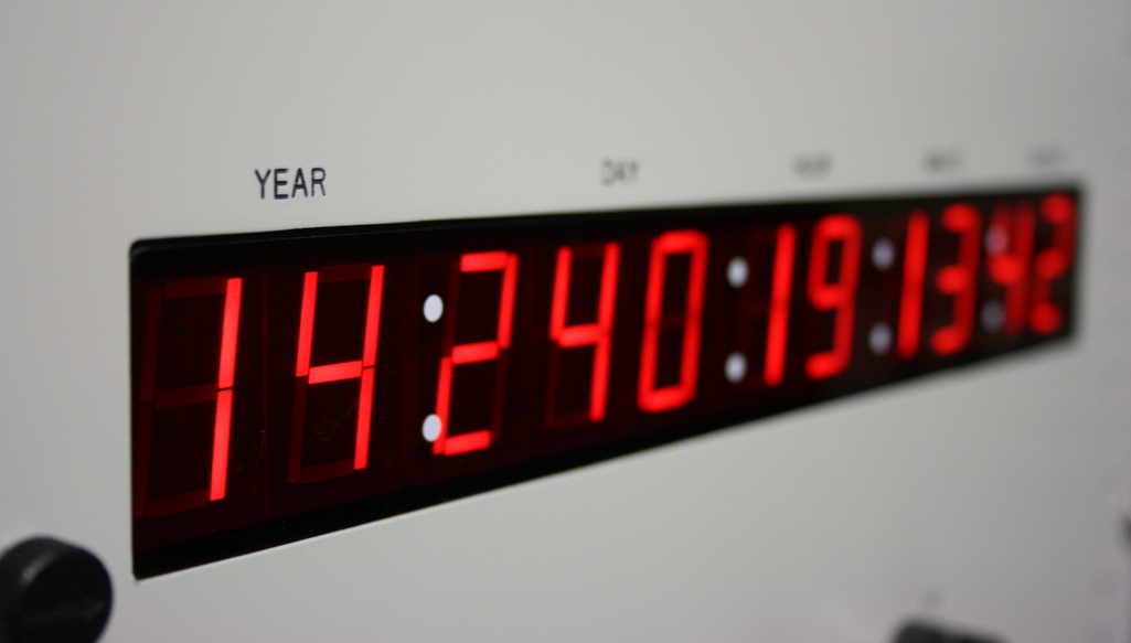
A WWV Time Code Generator

Many thanks to SWLing Post contributor, Jock Elliott, who shares the following guest post:


It’s about time . . . and beacons

By Jock Elliott, KB2GOM

Shortwave time stations can be incredibly useful for shortwave listeners, not just for checking the time, but also for finding out what’s going on with radio signal propagation. What makes these stations particularly valuable is that they are available all the time. I use them often when I am testing radio equipment or tweaks to my listening post.

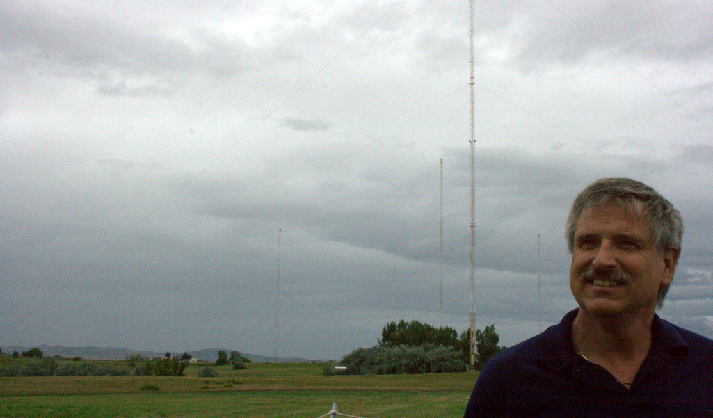
Chief Engineer Matt Deutch at WWV/WWVB. (Photo: Thomas)

The National Institute of Standards and Technology (part of the U.S. Department of Commerce) maintains a couple of stations devoted to broadcasting time announcements, standard time intervals, standard frequencies, UT1 time corrections, a BCD time code, and geophysical alerts 24 hours a day, 7 days a week.

WWV in Fort Collins, Colorado, according to NIST:

“radiates 10 000 W on 5 MHz, 10 MHz, and 15 MHz; and 2500 W on 2.5 MHz and 20 MHz. Each frequency is broadcast from a separate transmitter. Although each frequency carries the same information, multiple frequencies are used because the quality of HF reception depends on many factors such as location, time of year, time of day, the frequency being used, and atmospheric and ionospheric propagation conditions. The variety of frequencies makes it likely that at least one frequency will be usable at all times.”

In addition, WWV broadcasts the same signal heard on the other WWV frequencies on 25 MHz on an experimental basis. The power is 2500 W and, as an experimental broadcast, is may be interrupted or suspended without notice.

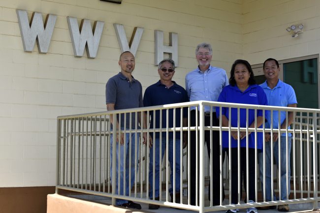
WWVH crew from left to right: Dean Takamatsu, Dean Okayama, Director Copan, Adela Mae Ochinang and Chris Fujita. Credit: D. Okayama/NIST

WWVH, based in Kekaha, Hawaii, transmits 10000 W on 10 MHz and 15 MHz, and 5000 W on 2.5 MHz. A NIST notes that the 5 MHz broadcast, which normally radiates 10 000 W, is currently operating at 5000 W due to equipment failure.

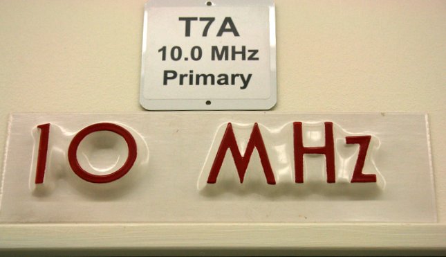
Photo Thomas (K4SWL) took in 2014 of the sign above WWV’s primary 10 MHz transmitter.

Both stations have voice announcements. WWV uses a male voice; WWVH, a female voice. They are staggered in time so that they don’t talk over each other. While doing research for this blog, one afternoon on 5 MHz and 10 MHz, I could hear the female voice, followed by the male voice, so I was hearing both Hawaii and Colorado. On 15 MHz, I could hear only Hawaii. Both stations transmit in AM mode, although I sometimes use upper sideband to pick the signals out of the noise.

CHU’s QSL card used in the 1980s depicting Sir Sanford Fleming, father of uniform times zones.

In addition, there is a Canadian time station. CHU transmits 3000 W signals on 3.33 and 14.67 MHz, and a 5000 W signal on 7.85 MHz.

The frequencies were chosen to avoid interference from WWV and WWVH. The signal is AM mode, with the lower sideband suppressed.

The same information is carried on all three frequencies simultaneously including announcements every minute, alternating between English and French. The CHU transmitters are located near Barrhaven, Ontario.

According to a posting on Radio Reference, there is also a time beacon in Moscow, Russia that transmits on 9996 and 14996 kHz in CW mode. I have never heard that station.

If anyone knows of additional shortwave time stations, please post the information in the comments section below.

Beacons

Another “standard reference” that can be used to figure out what’s happening with shortwave propagation is the International Beacons Project, a worldwide network of radio propagation beacons. It consists of 18 Morse code (CW) beacons operating on five designated frequencies in the high frequency band. The project is coordinated by the Northern California DX Foundation (NCDXF) and the International Amateur Radio Union (IARU).

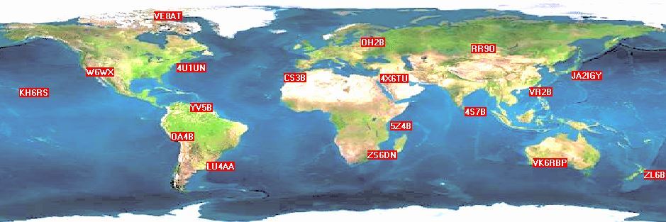
This page shows the locations of the beacons and gives samples of the signals that can be heard. Each beacon transmits once on each band once every three minutes, 24 hours a day. A transmission consists of the callsign of the beacon sent at 22 words per minute followed by four one-second dashes. The callsign and the first dash are sent at 100 watts. The remaining dashes are sent at 10 watts, 1 watt and 100 milliwatts. At the end of each 10 second transmission, the beacon steps to the next higher band and the next beacon in the sequence begins transmitting.

Clicking around the International Beacons Project website will reveal a wealth of information, including a Reverse Beacon Network — https://www.ncdxf.org/beacon/RBN.html — no kidding.

Finally, if you would like to disappear down the rabbit hole of chasing shortwave beacons, here is a list of 411 beacons around the world: http://www.dl8wx.de/BAKE_KW.HTM

The listing includes the frequency, the location, and the power of the transmitter (among other things). If any reader has experience with these beacons, please post in the comments section.

Spread the radio love

Radio Waves: Holme Moss Transmitter, Sherwood Tools, World of LPFMs, Shortwave Revival Response, and Russia “Thrown Back 40 Years”

Radio Waves:  Stories Making Waves in the World of Radio

Welcome to the SWLing Post’s Radio Waves, a collection of links to interesting stories making waves in the world of radio. Enjoy!


Holme Moss transmitter (BBC Archives)

A look at how the BBC’s third television transmitter in West Yorkshire was built.

These original masts broadcast to the surrounding population until 1985, when they were replaced by a new generation of transmitters.

Originally broadcast 12 October 1951

Click here to watch the video at the BBC Archives.

Sherwood Tools Available (K4FMH Blog)

The work that Rob Sherwood NC0B has contributed to the public over the past decade is unique and an amazing service to hams worldwide. I’m talking about, of course, his summary Table of receive bench tests published at this Sherwood Engineering website. He is independent so no one can think that advertising dollars could skew his assessments or how he presents them. As a CW contest operator, he is very clear that he sorts his table on the basis of what his experience and training has shown him to be the single most important measurement in his table: the narrow dynamic range.

I am not a CW operator or accomplished contester (lol) but enjoy the latter with my small team of fellow hams. But I am a statistician who likes to focus on problems where analytic tools can help foster a wider understanding of the data surrounding the problem area. So, working with Rob NC0B, I’ve created a set of “Sherwood Tools” to visualize his data as well as link them to a couple of other critical aspects of a rig purchase: market-entry price, consumer satisfaction, and the year the radio entered the market. These four vectors of data drive all of these tools, now available over at foxmikehotel.com.

The tools include a sortable Sherwood list where you can sort on any of the nine tests he publishes as well as the composite index of them that I created and included in my two-part NCJ articles in 2021. A set of 3D data visualizations are available to simultaneously view radios on four data elements (that does make it 4D, technically). Several graphs illustrate key aspects of the data, including how to not get tripped-up in the “ranking” of radios where the bench measurements are just not appreciably different. Seeing how the past 50 years of radios appearing in Rob’s Table have made a remarkable and clear progression toward the best receiver performance that modern test equipment can detect is in another tool. In addition, how the trend in getting a receive bang-for-the-buck has progressed over this 50 year period is there, too. Finally, I’ve used the industry-standard tool by Gartner, the Magic Quadrant, to help isolate radios in Rob’s Table that perform and are rated above average at various price points. I call these the Golden Quadrant Lists. Continue reading

Spread the radio love

Today (14 May 2022): Annual Armed Forces Day Crossband Test

Many thanks to SWLing Post contributor, Ulis (K3LU), who notes that today is the annual Armed Forces Day Crossband Test.

Click here to download a PDF document with all details including frequencies, schedule, and QSL info. Thanks for the tip, Ulis!

Spread the radio love

Frans uses SDR-Control with his IC-R8600

Many thanks to SWLing Post contributor, Frans Goddijn, who shares the following article and video originally posted on his blog:


SDR-Control for iCOM IC-R8600 (and bhi DSP demo)

The new SDR-Control app that lets you use certain iCOM radios as remote controlled SDR stations for Macbook or iPad does not yet (May 2022 now) officially support my iCOM IC-R8600 but Marcus Roskosch from https://roskosch.de/ told me that he recently purchased an IC-R8600 and the app already works on an experimental basis.

I immediately bought the app, installed it on my MacBook, connected a network cable between home router and radio and tried it out…

I also show how I use bhi DSP units to filter out noise to enhance speech at the radio and at the computer audio.


Spread the radio love