Many thanks to SWLing Post contributor, Guy Atkins, for the following guest post:
Radio Cook Islands
by Guy Atkins
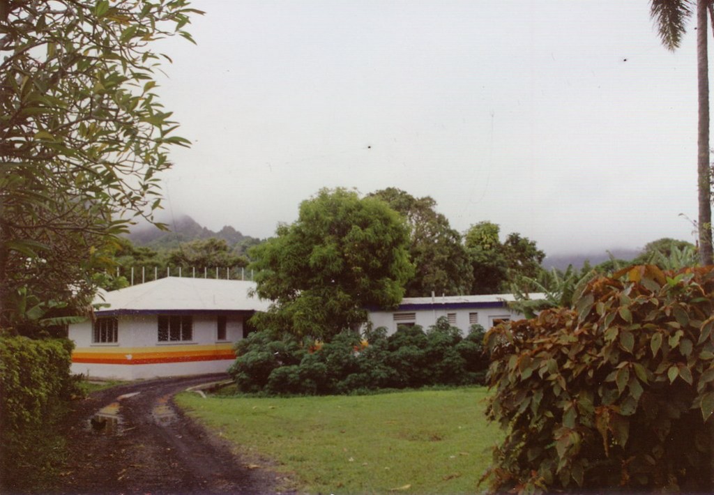
A view from the driveway entrance to the Radio Cook Islands studio in 1993. Insulators on an antenna (T2FD or multiband dipole) can be seen as dark spots against the cloudy sky. A feedline is also seen rising above the left side of the building. (Photo: Guy Atkins)

(Photo: Universal Radio)
In 1993 I was fortunate to have the opportunity to visit Rarotonga with my wife, courtesy of a nice award through my company which afforded me an all-expenses-paid trip anywhere we’d like to go.
I chose the South Pacific island of Rarotonga, partly because I wanted to visit Radio Cook Islands after listening to their “island music” on 11760 and 15170 kHz through my teenage years.
During our visit to the island I recorded 90+ minutes of RCI on 630 kHz with a local quality signal using a Grundig Satellit 500 and a Marantz PMD-221 recorder.
Recordings
The programming of Radio Cook Islands is bilingual, and announcers are fluent in both English and Cook Islands Maori. Music selections on RCI encompass all styles, to appeal to many age groups. These recordings was scheduled to include as much local music as possible.
RCI programming includes all the hallmarks of a small, non-professional station: stuck records & tape carts, dead air, poor modulation, and other miscues.
However, that’s part of the flavor of local radio, and these errors are heard throughout this recording. Particularly noticeable is the bassy, over-modulation of the studio announcer during sign-on announcements.
Notes: National anthem & hymn; sign-on announcements & music.
Music; weather; sign-off announcements & national anthem.
Local & regional news; weather; ads; music.
Notes: “Party Time” music request show; weather; local ads; more music.
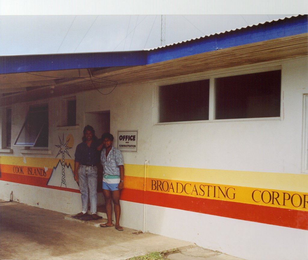
Two engineers from Radio Cook Islands, photographed during my visit in April, 1993. (Photo: Guy Atkins)
Sadly, RCI will likely never be on shortwave again; a fire in the local tele-comm building a few months before my 1993 visit destroyed RCI’s transmitter. I had an amusing exchange with the secretary when I visited; she insisted that their station was still on shortwave. Of COURSE we’re on the air she said, because “the frequencies are published right here in the newspaper!” The engineer and announcer confirmed, though, that the silence on their former frequencies was for real. They indicated they were covering the outer islands just fine with FM translators and had no intention of restarting shortwave.
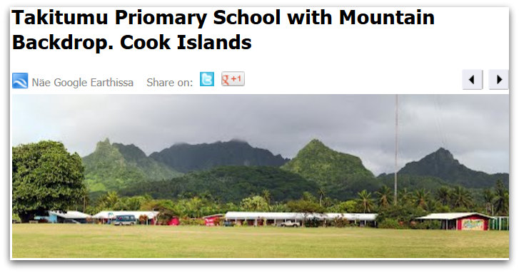
Radio Cook Islands 630 kHz antenna on the school ground of Takitumu Primary School.
RCI’s headquarters is in downtown Avarua, and their 5 kw transmitter (reported at half power, 2.5 kw in Dec. 2012) and modern quarter-wavelength vertical antenna is located in the town of Matavera (northeast side of Rarotonga).

Bing.com maps view of Radio Cook Islands antenna, 630 kHz at Takitumu Primary School, Matavera.
The antenna is in the yard of Takitumu primary school; see photos from Bing Maps and Panaromio [above].
It sure brings back a flood of good memories when I listen to these MP3s! I’d love to visit the Cooks again sometime.
Many thanks for this wonderful stroll down memory lane, Guy–radio nostalgia at its best!
I, too, would love to visit the Cook Islands someday–it is on my bucket list. In the meantime, I’ll enjoy your recordings. Again, many thanks for your guest post!