Category Archives: Antennas

A happy accident, and some experiments

By Jock Elliott, KB2GOM

When you live in an antenna-challenged situation as I do (stringing long wire antennas outside is problematic for me), the result is a never-ending search for an improved signal.

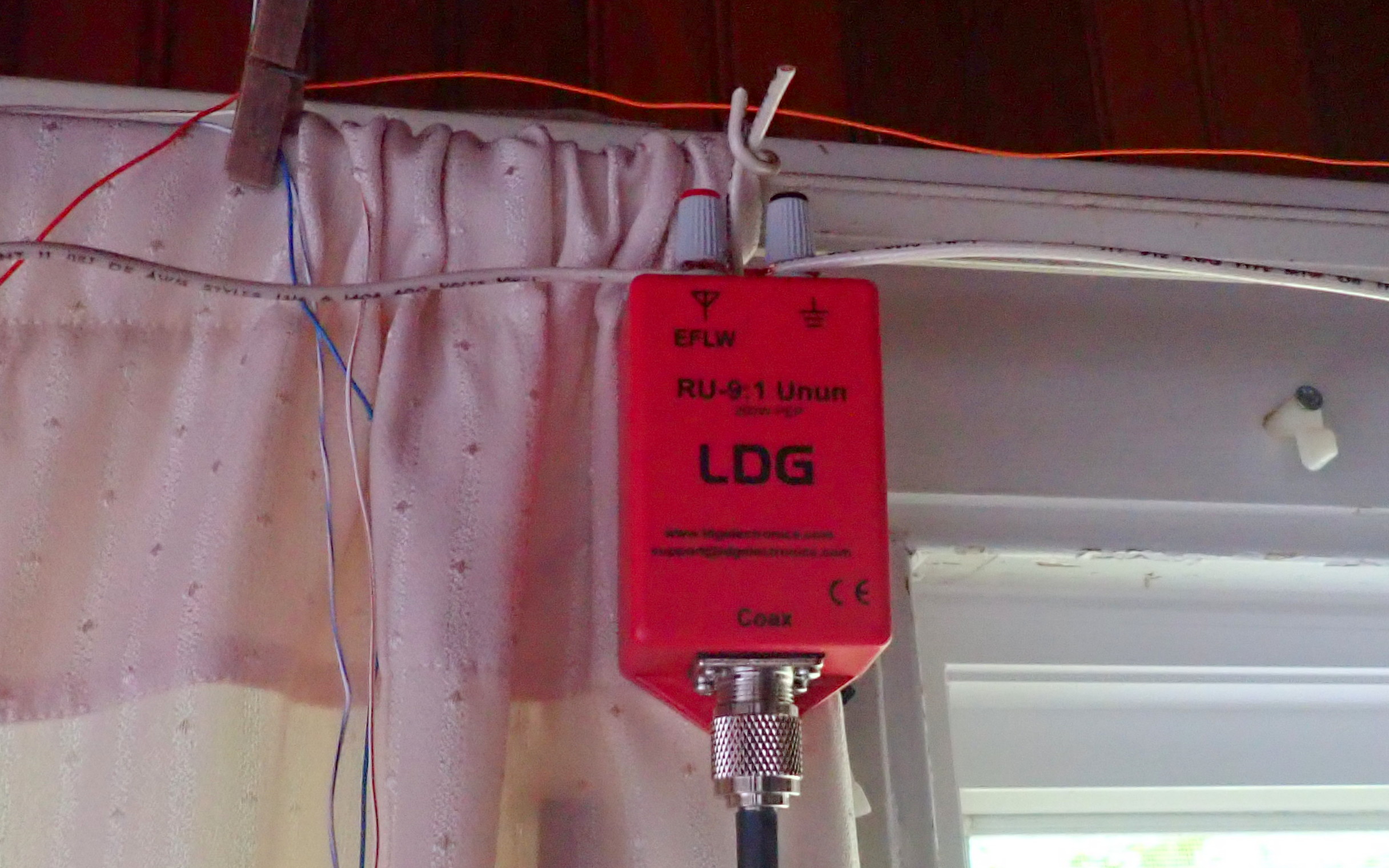
Toward that end, I’ve experimented with a horizontal room loop, an indoor end-fed, and a short dipole.

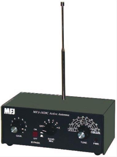
Along the way, I decided to test the MFJ 1020C active antenna/preselector, and I liked it pretty well. My conclusion was: Bearing in mind that it won’t improve every signal you want to hear, if you live in an antenna-challenged situation, the MFJ 1020C – particularly if you can get 20-50 feet of wire outdoors or run around the perimeter of a room – may be just what the doctor ordered.

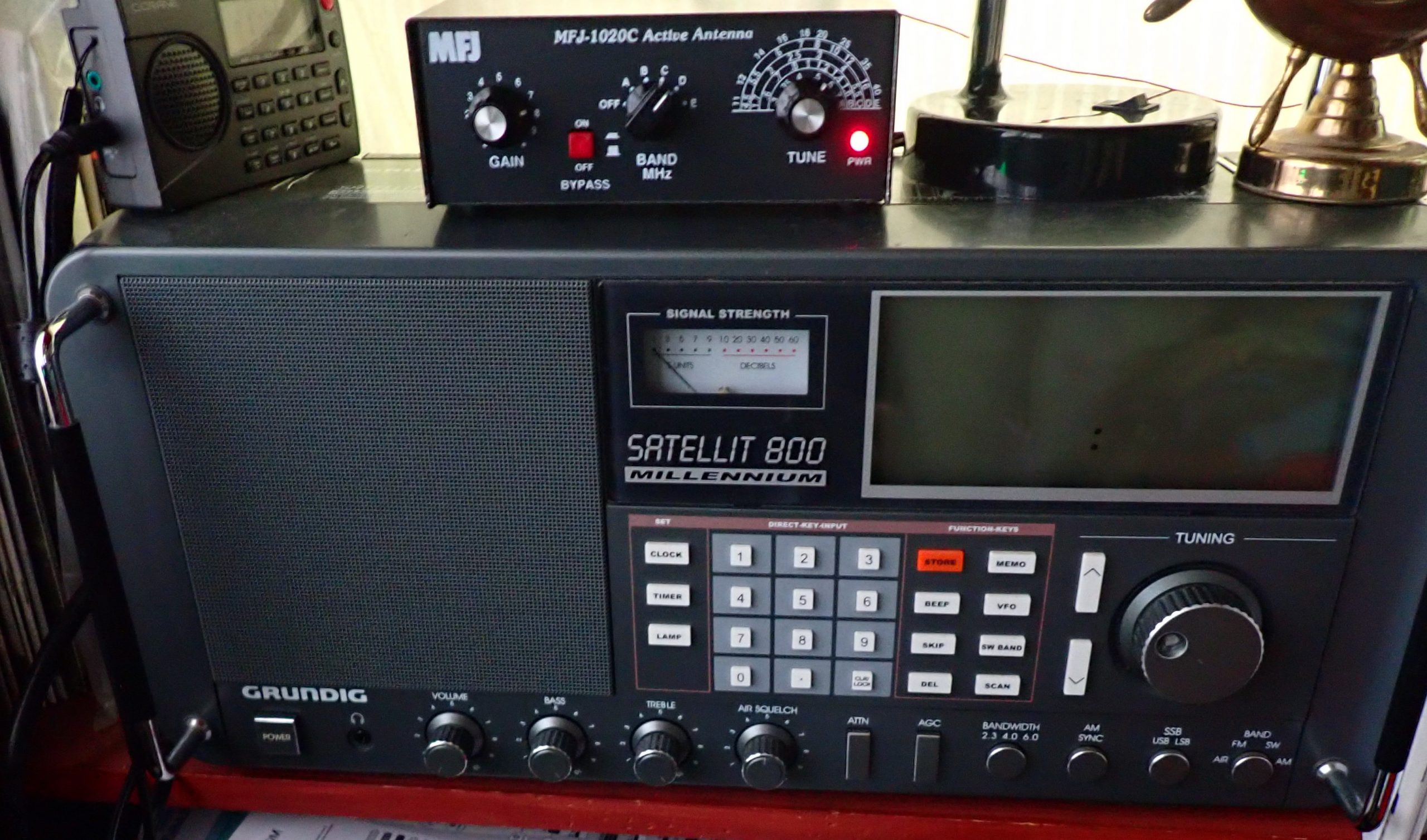
After my test of the 1020C, I had an online conversation with Andrew (grayhat), and he suggested that I might want to have a look at the MFJ 956 passive selector.  Its major claim to fame is: “Boost your favorite stations while rejecting images, intermod, and phantom signals!  The MFJ-956 Pre-Selector/Antenna Tuner greatly improves reception from .15 to 30 MHz — especially below 2MHz.  It has tuner bypass/ground receiver positions.  The MFJ-956 measures a compact 2 x 3 x 4 inches.

MFJ was kind enough to send a 956 to me, and while I did not test it below 2 MHz, I found that it proved very helpful in tuning in the BBC mid-winter broadcast to Antarctica. I started out with the MFJ 1020C. Lots of noise and fades. Reception was somewhat better using the 1020C (compared to bypass), but then I switched to MFJ 956. I found I could copy better with the 956, even though it provides no amplification. Tuning slightly off-peak offered the best copy, better than bypass. I was listening in USB. In all, it is a useful piece of gear.

While poking around the MFJ website I discovered the MFJ 1046 Receiver Preselector, 1.6-33 MHz. Among other claims, MFJ has this to say about the 1046: MFJs new Passive Preselector has extremely high dynamic range! It improves the performance of nearly any HF or shortwave receiver/transceiver. It vastly improves the most expensive receivers. Especially helpful to those with broadband front-ends that are prone to overload.

Sounds promising, I thought, so I emailed Thomas, SWLing’s Maximum Leader, to see if maybe MFJ would like me to have a look at one.

A happy accident

A few days later, package arrived.

I was unpacking it when the Brain Dudes interrupted.

Brain Dudes:  Hey!!

Me: What?!!

Brain Dudes: That thing look a little weird to you?

Me: Whaddya mean?

Brain Dudes: Look at the front . . . what do you see?

Me: Well, on left, a knob labeled GAIN; next to that, and ON/OFF button; moving to the right, a BAND selector switch, and finally a TUNE knob.

Brain Dudes: And what is the MFJ 1046 supposed to have?

Me: A big tuning knob, an ON/OFF switch, and a BAND selector switch . . . maybe this is an improved model . . .

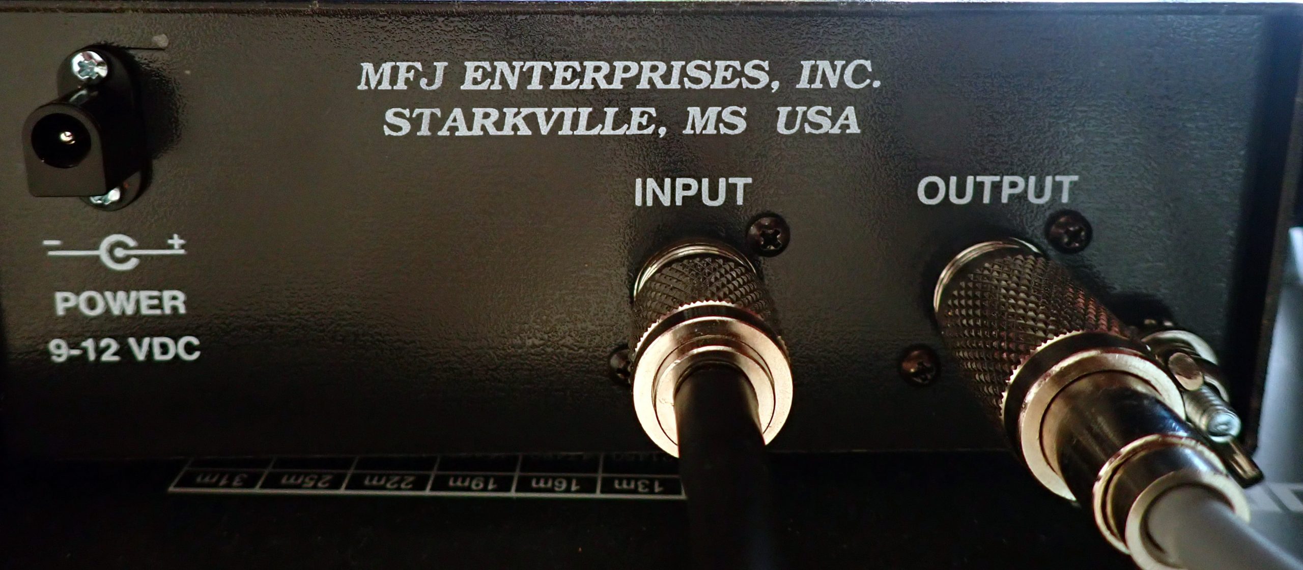
Brain Dudes: How ‘bout you look on the back panel . . . what do you see?

Me: The usual connections for antenna and receiver . . . and a plug-in socket for an external power supply.

Brain Dudes:  Is a passive preselector supposed to have a power socket?

Me: No . . .

Brain Dudes: OK, final clue, Sherlock: suppose you read the label on the front panel.

Me: MFJ 1045C. Holy smokes! They sent me the wrong unit!

(I hear the Brain Dude yelling at someone in the background: “Finally, the light comes on! I told you switching to decaf was a bad idea!)

Brain dudes: So they sent you the wrong unit; suppose you test it anyway since it’s here.

So I did. And it turns out that MFJ sending the 1045C instead of the 1046 was a happy accident because the 1045C, which is an active preselector, delivers excellent performance across the board.

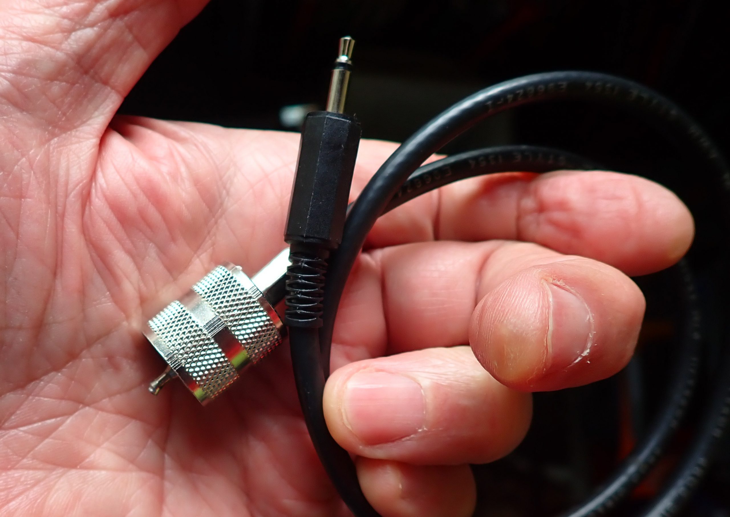
This is what MFJ says about the 1045C: “Lets you copy weak signals. Rejects out-of-band signals, images. 1.8 to 54 MHz. Up to 20 dB gain. Gain control. Dual gate MOSFET, bipolar transistors for low noise, high gain. Connect 2 antennas, 2 receivers. Coax and phone jacks. 9-18 VDC or MFJ-1312D.

Once the antenna, receiver, and power supply are connected (I used the power supply that MFJ sent me with the 1020C), I operate the 1045C in much the same way as the 1020C:

  1. With the unit in BYPASS mode (the ON/OFF button out), tune the receiver to the frequency you want to hear.
  2. Set the GAIN knob to around 3 or 4.
  3. Set the BAND knob to the band with the MHz that you are tuned to.
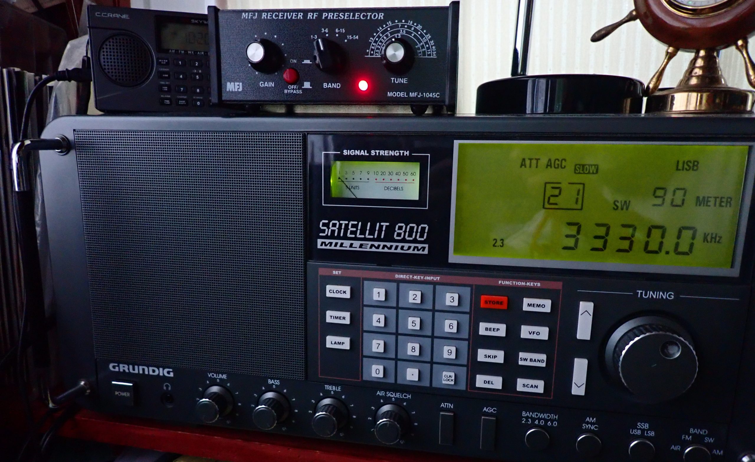
  4. Press the ON/OFF/BYPASS button in. This turns on the active preselector and amplification circuits and a red light comes on to let you know the unit is activated.
  5. Slowly turn the TUNE knob back & forth. At some point in its tuning range, you will hear the signal and/or noise peak.
  6. Finally, adjust the GAIN knob for maximum intelligibility of the signal. Sometimes tuning slightly to the side of the peak works best.

I tested the MFJ 1045C with my end-fed indoor antenna (see link above) and with the short dipole (also, see link above). I also did head-to-head comparisons with the MFJ 1020C and those two antennas.

The results

Here’s what I found:

  1. The indoor end-fed antenna (which is 45 long) out-performs the short dipole (which is 6 feet total length) in all cases. That’s no surprise, but bear in mind that not everyone has a situation in which they can deploy the longer antenna. The 6-foot dipole definitely out-performs the whip antenna on my Satellit 800.
  2. The 1045C has a broader range of amplification than the 1020C. It appears to reject adjacent channel interference as well or better than the 1020C, and, to my ear, the 1045C has a lower noise floor. If you turn the GAIN knob fully to the left, it gets to a position where it appears to actually attenuate the signal. And I never found a situation in which, if properly tuned, the signal delivered by the 1045C was at least equal to the bypass signal, and many times it was significantly better. In short, in the HF range the 1045C appears do to everything that the 1020C does (with the exception of the 1020C’s screw-in whip antenna) and do it better.
  3. When using the 1045C with a portable (my Tecsun 880), I found that I could hear the noise peaks better than with the 1020C, which is a great help in tuning for best performance.

So why would you chose the 1020C or the 956 over the 1045C? Short answer: if you are a MW or LW enthusiast. According to MFJ, the 1045C covers 1.8 to 54 MHz; the 1020C covers .3 to 40 MHz, and the 956 covers 150 kHz to 35 MHz.

However, if you are an HF weenie like I am who enjoys teasing out faint signals, and particularly if you are faced with a sub-optimal antenna situation, the MFJ 1045C, in my opinion, is definitely worth a try.

Click here to check out the MFJ-1045C.

Shameless plug: check out the SWLing Post Message Board there are often interesting discussions going on there.

Radio Waves: New Yaesu FT-710 AESS, Ukraine’s Army FM, Foil 28 MHz antenna, and ATS-25 4.1 Firmware Review,

The Yaesu FT-710 AESS

Radio Waves:  Stories Making Waves in the World of Radio

Welcome to the SWLing Post’s Radio Waves, a collection of links to interesting stories making waves in the world of radio. Enjoy!

Many thanks to Eric Jon Magnuson for summarizing these news items for Radio Waves!


Yaesu Introduces the FT-710 AESS 100 SDR Transceiver (QRPer.com)

Yaesu is introducing a new 100 watt SDR transceiver to their product line: the Yaesu FT-170.

The Yaesu FT-710 will cover 160-6 meters with 100 watts output. There are two other Japanese market versions: the FT-710M and FT-710S which are 50 and 10 watt respectively.

This general coverage rig will feature “AESS”–Yaesu’s ‘Acoustic Enhanced Speaker System’ which “creates the high-fidelity audio output.” Yaesu notes that the FT-710 utilizes, “the advanced digital RF technology introduced in the FTDX101 and FTDX10 series.”

Click here to check out the published features and specifications of the new FT-710.

Ukraine’s ‘Army FM’ Radio Adapts To Full-Scale War (CoffeeOrDie)

KYIV, Ukraine — During the early morning hours of Feb. 24, as Russian missiles struck targets across Ukraine in the opening hours of the full-scale war, the Ukrainian military’s Army FM radio station went underground.

The team of seven army officers and about 10 civilian personnel abandoned their studio on the top floor of a downtown Kyiv building and relocated into a nearby basement. Inside the dank and dark underground space, they connected a mixing board and a couple of laptops to a mobile radio system, which the station’s reporters had previously used to report from the Donbas trenches.

“I just grabbed my Kalashnikov and went to work,” said Oleksandr Yurchenko, 32, a Ukrainian army second lieutenant assigned to Army FM.

While a Russian invasion force advanced to the outskirts of Kyiv in the war’s perilous first few days, the Army FM team stayed at their posts and worked in six-hour shifts to keep their programs running 24/7. They constructed makeshift beds from shipping pallets and stocked the basement studio with food and water. Body armor vests and Kalashnikovs occupied all available shelves and empty corners.

From this jury-rigged basement studio, Army FM continued to transmit information and entertainment programs to listeners across Ukraine — including into territories Russian forces invaded and occupied. [Continue reading…]

Hackaday: Homemade 28 MHz antenna made from foil (Hackaday via the Southgate ARC)

On Hackaday Chris Lott WD4OLP writes about DL1DN’s aluminum foil 20cm antenna for 28 MHz (10m) operation

David DL1DN, is an Amateur Radio enthusiast with a penchant for low-power (QRP) portable operations. Recently he was out and about, and found that 10 m propagation was wide open. Not discouraged by having forgotten his antenna, he kludges up a makeshift one using a 20 cm length of aluminum foil.

Read the Hackaday story and watch the video at
https://hackaday.com/2022/07/02/aluminum-foil-20-cm-antenna-for-10-m-operation/

Dave reviews the ATS-25 with Binns 4.1 firmware

Dave Zantow writes:

ATS-25 with Binns 4.1 firmware Review Now Posted. […] There were 7 different versions in the beta stage. New audio file added as well (Sync when it does not work so well, which is NOT all the time). Might be one more update before release (not sure right now).

Click here to check it out.


Do you enjoy the SWLing Post?

Please consider supporting us via Patreon or our Coffee Fund!

Your support makes articles like this one possible. Thank you!

The solution for apartment/condo dwellers, perhaps?

By Jock Elliott, KB2GOM

It was research on preselectors that led me to this: Improving HF Reception – The RadioReference Wiki

In that section of the RadioReference Wiki, written by Mike, KA3JJZ, I found the following:

Another way an active preselector could be used is to use it to load a very short dipole – say not more than 1 meter (roughly 3 foot) for each leg. A number of years ago, a company called Datong marketed such an antenna (with a preamp right at the antenna feedpoint) that was popular in Europe and to some lesser extent in the Americas because it’s easy to hide the antenna.

In the magic of my mind, I could picture using the short dipole strung across two windows — or a large window — in an apartment or condo (or anyplace with antenna restrictions) and connected to an MFJ 1020C. I had not yet done the experiment, but I had tested the 1020C and found it to be a worthy piece of gear. So I thought the short dipole/1020C experiment might be worth a shot.

The heart of the short dipole, the LDG 9:1 unun.

So I cut two yard-long lengths of wire and attached them to a 9:1 unun. I created loops at the outer end of each leg of the dipole and hung the whole assembly from a curtain rod covering two windows. A coax links the short dipole to the MFJ 1020C, and a jumper connects the output of the 1020C to my Satellit 800 receiver.

The completed dipole. Not fancy, but it works.

Bottom line: it works. The vast majority of the time, even when the 1020C preselector is in bypass mode, the short horizontal dipole/1020C combo delivers a better signal-to-noise than the Satellit’s vertical telescopic antenna. (In rare cases, they are equal.) And when the preselector amplification circuits are activated and properly tuned, the signal is usually improved, often significantly. The Big Trick is to use the preselector to peak the noise at the frequency you want to hears and then tune slightly to the side of best listening.

Obviously that would be cumbersome for band-scanning, but you could band-scan in bypass mode and then tweak the “hits” with the amplification circuitry. In all, if you are living in an antenna-challenged situation, the short dipole/1020C combo just might make your shortwave listening better.

Final thought: Mike, who wrote the section of Radio Reference wiki that inspired this experiment, said:

You do have to watch your gain otherwise you will get a lot more noise than signal. I did my experiment using an old Palomar preselector. You can also try using a YouLoop as the antenna – it should, in theory, work even better than just a simple whip.

One thing that you could mention in your article is that there is an advantage to having a small dipole like that as the receiving element. Not only is it fairly easy to hide, it can be moved around to find a somewhat quieter location. However the coax should be kept as short as you can, otherwise there is a chance that common mode noise would become an issue – particularly if it runs near computers or other RFI sources

Remember that even a 1 or 2 S unit improvement might make the difference between hearing a signal and not hearing it at all. All we are doing here is trying to improve the signal/noise ratio coming into the unit. That little vertical whip on the 1020c is not likely to be the best choice, and that’s what I am trying to improve upon.

– Mike KA3JJZ

Thanks, Mike!

Giuseppe’s latest homemade ferrite antenna for MW and SW

Many thanks to SWLing Post contributor, Giuseppe Morlè (IZ0GZW), who writes:

Dear friends,

I’m Giuseppe Morlè from Formia, central Italy on the Tyrrhenian Sea.

I want to share with you my latest ferrite antenna for listening; it is composed of 3 ferrites of 20 cm each in a tube for electrical systems with 2 separate windings, one for medium waves and one for short waves, 40 turns for medium waves, 4 turns for short waves. I use a 750 pf variable to tune the 2 windings and a switch is used to eliminate a winding.  Since there is only one variable, if you listen to the medium waves I interrupt the winding of the shorts.

On shortwaves it is preferable to place the system on an iron railing which, due to inductive effect, behaves like a really long wire antenna.

For the mediumwaves it is enough to bring the receiver close to the ferrites and also in this case, the induction will have its effect with an excellent increase in signal and modulation.

The range of this portable antenna is:

      • 520 to 1800 kHz
      • 3.500 to 18.000 MHz

Here’s a video from my Youtube channel where I explain how it works:

I had previously built a similar antenna but with 12 cm ferrites–very portable.

Thank you for your attention and I wish you good listening.

73. Giuseppe Morlè iz0gzw.

This is brilliant, Giuseppe! I love how you never stop building and experimenting with various antenna designs! Thank you for sharing this with us!

Giuseppe pairs his Kenwood R-1000 & Indoor Cross Loop Antenna

Many thanks to SWLing Post contributor, Giuseppe Morlè (IZ0GZW), who writes:

Dear Thomas and all friends,

This is Giuseppe Morlè, IZ0GZW, from Formia, central Italy on the Tyrrhenian Sea.

I went back to listening with my Kenwood R1000 and indoor homemade cross loops …this time a station in Kuwait, 9k2yd Younes on general call.

I used the 2 loops together and in the last part only the one in the East / West direction and I did not notice any changes. Very strong signals and good evening propagation at 18.00 utc today, 04 June 2022.

Note the absence of electrical noise; the S Meter remains at zero in the absence of modulation and signal.

I am always amazed at my indoor cross loops for the reception quality and they have become the main antenna of my Kenwood R1000.

Giuseppe I hope you enjoy the video
Greeting to all of you from central Italy.

Click here to view on YouTube.

Your cross loop antenna is an amazing QRM-fighter! Thank you for sharing this, Giuseppe. Most impressive and so good to see the R-1000 on the air.

Testing the MFJ-1020C Active Antenna/Preselector

By Jock Elliott, KB2GOM

Truth be told, I’ve been curious about the MFJ 1020C for a long time. Back when I wrote for Passport to World Band Radio, over a decade ago, I wondered if the 1020C was a worthwhile device, but then I had a big wire antenna outside connected to a communications receiver, so I didn’t worry so much about squeezing every last erg out of the signals I was receiving. As a result, I never experimented with an MFJ 1020C.

Now, however, I have a 50-foot indoor end-fed wire antenna connected to a Grundig Satellit 800, and I am constantly looking to improve the signal. Feeding the signal through a 9:1 unun and then through coax to the Satellit 800 has boosted the signal-to-noise ratio a bit — https://swling.com/blog/2022/05/the-satellit-800-the-tecsun-pl-880-and-two-indoor-antennas-an-afternoon-of-experimentation/ —  and so has grounding the unun — https://swling.com/blog/2022/05/jock-gets-a-good-grounding/. But is there such a thing as too much signal to noise? Not in my not-so-humble opinion, so the quest for improvement continues.

During a phone call with Thomas (Maximum Leader of SWLing.com), I mentioned my curiosity about the 1020C. Thomas said, “MFJ is a sponsor of SWLing.com, I’ll see if they would like to send you one for testing.” Two days later, a package arrived with the 1020C, a power supply for it, and a short coax jumper.

The Basic Layout

The 1020C is small — 2.5” H x 6.4” W x 3.3” D – and looks well made. It covers 300 KHz to 40 MHz. On the front panel are two knobs, a push button, and a selector switch. The left-most knob controls the gain of the amplifier. Moving to the right, you’ll find a push button that controls the bypass circuit.

To the right of the bypass button, you’ll find the band switch, which controls which frequency range is in use, and to the right of that is the tuning knob which allows you to peak the signal in the frequency range you have selected. We’ll get to how it all works in just a bit.

On the back of the 1020C, you’ll find a coax connector labeled INPUT and another labeled OUTPUT, a grounding post, and a connector for the external power supply.

Setup is easy. Plug the power supply into the wall and into the back of the 1020C. (You can also run the 1020C off a 9-volt battery, which we will discuss in a while.) Connect a coax jumper from the OUTPUT connector on the 1020C to the coax input on your receiver. (If you don’t have a coax connector on your receiver, we’ll deal with that issue shortly).

Finally, you need to make a choice about which antenna you want to use. The 1020C Owner’s Manual says:

You may connect either the telescoping antenna provided or an external wire antenna of your choice. To connect the telescoping antenna; screw the antenna end through the top cover and into the spacer located on the PC board. If you chose to use external wire antenna; plug it into the INPUT SO239 connector located on the back of the unit. (DO NOT HAVE BOTH ANTENNAS CONNECTED AT THE SAME TIME!)

Attaching the telescoping antenna can take a while since you may have to hunt around to get the antenna centered on top of the screw inside the 1020C’s case.

Operating the MFJ 1020C

Here’s how I operate the 1020C:

  1. With the BYPASS turned ON (the button pressed in), tune the receiver to the frequency you want to hear.
  2. Set the GAIN knob to around 3 or 4.
  3. Set the BAND knob to the band with the MHz that you are tuned to. You will notice that the red PWR indicator on the 1020C lights up.
  4. Press and release the BYPASS button. This turns on the active preselector and amplification circuits.
  5. Slowly turn the TUNE knob back & forth. At some point in its tuning range, you will hear the signal peak. With the 1020C, I often find there is a spot where the noise peaks and a hair to the side of the noise peak is the sweet spot for listening.
  6. Finally, adjust the GAIN knob for maximum intelligibility of the signal.

Note: When the BYPASS button is pushed IN (the ON position), that means you are hearing the signal straight through from the antenna without going through the amplification and preselection circuits of the 1020C . . . it’s like the 1020C isn’t even there. This is true even if the red PWR LED is illuminated. To put the 1020C to work for you, the BYPASS button must be OUT, and a band must be selected.

The Results of My Tests

Bottom line: the 1020C can really help in certain situations.

Initially, I set up the 1020C with its diminutive 20 inch antenna and connected a coax jumper cable between its coax output and the coax input on the back of the Satellit 800. I wanted to see if it would out-perform the four-foot-long telescopic antenna on the Satellit. No way, I thought; the Satellit antenna is twice as long. But I was wrong. On the first day I tested the 1020C, the atmospheric noise was terrible. I could not hear time station CHU on 3.330 MHz at all with the Satellit’s built-in antenna. But with the 1020C properly tuned, I could hear the time “pips” on CHU clearly.

A couple of days later, when SWLing.com announced the Annual Armed Forces Day Crossband Test —  https://swling.com/blog/2022/05/today-14-may-2022-annual-armed-forces-day-crossband-test/ — I set out to see if I could hear some of the stations. I removed the telescopic antenna from the 1020C and connected the 1020C to my indoor end-fed antenna. Putting the unit in bypass mode, I then started punching in the crossband test frequencies on the Satellit 800. At each frequency, I would first listen to the frequency in “barefoot” mode, then activate the 1020C to see if I could bring any intelligible signal up out of the noise. I had no success until I got to 14.487 MHz USB.  With the straight-through indoor end-fed antenna, I heard nothing, but with the 1020C engaged and carefully tuned, I could copy a station sending in CW: CQ CQ CQ. Later I was able to confirm the ID as NSS from Annapolis, Maryland, one of the stations in the crossband test.

On some easier-to-hear signals, the 1020C sounds as if it lowers the noise floor, improving the “listenability,” but the 1020C does not improve all signals. Sometimes the signal processed by the 1020C sounds roughly the same as the bypassed signal. And sometimes the bypassed signal (straight through from the antenna without the 1020C in-line) simply sounds better.

The pigtail.

Testing the 1020C with a Portable

Next, I tried the 1020C with my Tecsun PL-880. Immediately, I was confronted with a problem: how to get the signal from the coax output of the 1020C and into the antenna socket of the 880. Fortunately, a ham friend fabricated a “pigtail” for me that made the connection from the coax connector on the 1020C to the antenna input socket on the PL-880. As soon as I hooked it up, I heard an unpleasant hum that I had not heard on the Satellit 800.

I decided to see if running the 1020C off battery would offer an improvement. This involved another challenge: there is no “hatch” on the 1020C to provide access for plugging-in the 9-volt battery. Instead, you have to take out the screws on either side of the cabinet, remove the cabinet top, find the 9-volt connector hidden in a little plastic sleeve inside the 1020C, plug in the 9 volt battery, slide it into its clip, replace the cabinet top, and run the screws back in. That, in itself, is not difficult to do, but as soon as the battery needs replacing, you have to go through most of the process all over again.

The good news is that once the 1020C was running off battery, I could detect no hum, and the experience with the 1020C with the PL-880 was much the same as with the Satellit 800. Some signals were improved, some were the same, and sometimes the straight-through (bypassed) signal was better.

I have not tested the 1020C with a large, signal-devouring antenna out in the fresh air. The 2009 edition of Passport to World Band Radio offered that, with an inverted-L antenna longer than, say, 50-75 feet, the 1020C may not provide much benefit. However, my experience with a modest 50-foot indoor end-fed antenna demonstrates that the 1020C can deliver a significant signal boost in some circumstances, and I am glad to have it in my shack.

Bearing in mind that it won’t improve every signal you want to hear, if you live in an antenna-challenged situation, the MFJ 1020C – particularly if you can get 20-50 feet of wire outdoors or run around the perimeter of a room – may be just what the doctor ordered.

Suggestions for MFJ

There are three areas in which MFJ could make life easier for 1020C users: (1) make a pigtail or other device available to get the signal from any wire antenna to the coax input of the 1020C, (2) make a pigtail or other solution to bring a signal from the output of the 1020C to a shortwave portable (possibly a pigtail with an alligator clip to connect to the whip antenna), and (3) offer or provide quick-release pins for the 1020C cabinet for those who wish to operate it off batteries and want to be able to replace them quickly and easily.

Tecsun PL-990 Ferrite Rods

Many thanks to SWLing Post contributor, Gareth Buxton, who writes:

Hi Thomas

I see that Anon-co have the Tecsun PL-990 Ferrite rod aerial for sale. It even says in the product description “You can use it for your DIY projects.” I thought it might be of interest to your MW/AM radio constructors, especially if they can build a radio that receives more stations than the Tecsun using the same part!

Click here for the product page at Anon-Co.

Cheers
Gareth

Thanks for the tip, Gareth. This would indeed make it easy to construct an external MW antenna. Thank you for the tip!