Radio Waves: Stories Making Waves in the World of Radio
Because I keep my ear to the waves, as well as receive many tips from others who do the same, I find myself privy to radio-related stories that might interest SWLing Post readers. To that end: Welcome to the SWLing Post’s Radio Waves, a collection of links to interesting stories making waves in the world of radio. Enjoy!
Many thanks to SWLing Post contributors Aaron Kuhn, Ron Chester, Ronnie Smith, Dan Van Hoy, and Dennis Dura for the following tips:
KTNN radio station’s headquarters in St. Michaels, Arizona is less than ten minutes away from the Navajo Nation capital of Window Rock, but its reach encompasses all 27,000 square miles of the Nation across four different states. The station has been broadcasting bilingual content in both the Navajo language, Diné Bizaad, and English for over 35 years. But the station is quiet nowadays — many staff members are working from home if they can. That includes Dee Dixon who, after 15 years at KTNN, had to install internet access to her home an hour and a half away in Dilkon, Arizona so she could broadcast her 6AM show.
Her regular listeners are scattered. During the day, KTNN covers the majority of the Navajo Nation across New Mexico, Arizona, Colorado, and Utah. One can also tune into KTNN’s programming online via livestream from anywhere in the world. It is not the region’s only media. A few regional newspapers cover the reservation extensively, and Navajo Nation is also the only tribe in the country that owns, funds, and operates its own television station. But none of these mediums produce stories primarily in Diné Bizaad: radio is the only way to hear the language in local media.
When the COVID-19 pandemic bore down on Navajo Nation in early 2020, Dixon noticed a distinct divide between her regular listeners at home on the reservation and those outside of it. As Dixon worked on translating public health announcements and taking calls on the air, she noticed an uptick in listeners tuning in from Florida, Maine, Alaska, Louisiana, and Montana. Those callers away from home were hungry for local updates to know what was going on within the Nation — an ambiguous virus that no one understood thoroughly just yet was spreading. People wanted to know if their families were safe and just how transmission was occurring in a place where households are far flung across vast swaths of desert. But Dixon realized as her local listeners, specifically elders, called in that they wanted something different from her: they did not want to hear about the virus whatsoever, no matter how high the rates of infection in Navajo Nation were.
“According to Navajo tradition, you’re not supposed to give a name to anything that is not good for the reservation,” Dixon says. “The virus was like a monster. Traditionally, the more you talk about something like that, the more you’re inviting it into your home.”
Navajo Nation is the second-largest Indigenous tribe in the country with about 300,000 enrolled members, over half of whom live on the reservation. Much of the land is rugged and rural. Of those on the reservation, about 27 percent of households do not have electricity. Cellphone service can be spotty to nonexistent.
But transistor and car radios do not require electricity to function. Radio waves are not dependent on cell towers. In fact, KTNN was the last station in the country licensed for a clear-channel radio signal at 50,000 watts — a strength used in the early 1900s to provide rural America with radio that wouldn’t be vulnerable to interference.[…]
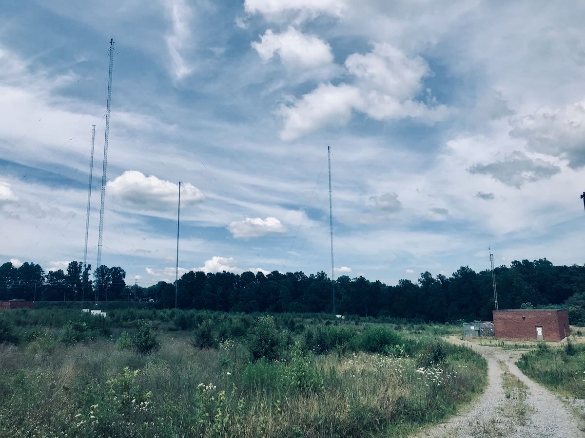
KOGA, Ibaraki Prefecture–Standing tall and proud over an area of 1 million square meters or so, a forest of steel towers in two-tone red and white is the dominant feature under the blue sky against the backdrop of Mount Tsukubasan.
This is KDDI Corp.’s Yamata Transmitting Station, the nation’s only facility broadcasting shortwave radio programs to overseas listeners.
The station started broadcasts on Jan. 1, 1941. The main building still retains a prewar ambience.
Shortwave radios were the primary means for people across the world to receive audio content from Japan without a large-scale facility before satellites and submarine cables came into existence.
The 1945 announcement of Japan’s surrender by Emperor Hirohito was transmitted from here to military personnel on overseas battlefronts.
When it was completed in 1940, Yamata, now part of Koga, was a typical farming village with a population of 4,536, of whom 90 percent were farmers, according to a 1941 local history pamphlet.
“A large area of flatland was available, and it was less prone to damage from snow and typhoons,” said Kazuhiro Matsui, 50, a senior official in charge of infrastructure, who served as a guide when the station was shown to media representatives in April. “I think it was the only place fit for the station in the country.”
The steel towers are arranged in such a way that 18 transmission antennas cover 360 degrees to send broadcasts as far north as Boston and London and as far west as Seoul and Nairobi.[…]
ARRL The National Association for Amateur Radio® and Mag Instrument, the US manufacturer of the MAGLITE® Flashlight have announced they have formed a partnership based on common interests in equipping people to be prepared for emergencies and to serve their communities in extreme situations such as natural disasters. ARRL members expand the reservoir of trained operators and technicians in radio communications and radio technology, and provide public service through the ARRL Amateur Radio Emergency Service® (ARES®). Maglite is the leading maker of U.S.-manufactured high-quality flashlights that have a deserved reputation for toughness and durability.
“Amateur radio operators, or ‘hams,’ help people in times of difficulty, often by supporting emergency communications when critical infrastructure is damaged, and by aiding first responders’ need to keep connected,” said Anthony Maglica, Founder, Owner and CEO of MAG Instrument Inc. “We manufacture a product that has been used in public safety for over 40 years, and we are very supportive of the incredible dedication of radio amateurs, so culturally this is a great alliance for both brands.”
“ARRL is delighted that Maglite recognizes the service and skill of ARRL members. This partnership will help us introduce amateur radio to more people,” said David Minster, NA2AA, ARRL CEO. Mag Instrument is creating a special laser-engraved Maglite® product collection for ARRL, as well as offering their members special pricing on a select line of Maglite gear. In turn, those purchases raise funds to support ARRL’s mission. Members can find details at www.arrl.org/benefits and by clicking “Member Discounts” in the left-hand navigation on that page.
Maglite is also promoting a special giveaway in recognition of 2021 ARRL Field Day (no purchase is necessary). Visit Maglite on the web for entry details and Terms and Conditions at https://maglite.com/pages/the-maglite-arrl-2021-field-day-giveaway.
ARRL, headquartered in Newington, Connecticut, counts the majority of active radio amateurs in the US among its ranks. Since its founding in 1914, ARRL and its members have advanced the art, science, and enjoyment of Amateur Radio.
For more information about ARRL visit www.arrl.org.
At the FCC’s upcoming July Open Meeting scheduled for July 13, Acting Chairwoman Jessica Rosenworcel has proposed voting on seven rule changes to eliminate those that are “redundant, outdated or in conflict” with other rules.
The seven changes are described as:
1. Eliminate the maximum rated transmitter power limit rule for AM stations set out in section 73.1665(b)[…]
2. Update the NCE FM community of license coverage requirement set out in sections73.316(c)(2)(ix)(B) and 73.1690(c)(8)(i) to match that used in section 73.515;
3. Eliminate the requirement that applicants demonstrate the effect of any FM applicant transmitting antenna on nearby FM or TV broadcast antennas set out in section 73.316(d);
4. Update the signal strength contour overlap requirements for NCE FM Class D stations set out in section 73.509(b) to harmonize with the contour overlap requirements for all other NCE FM stations, set out in section 73.509(a);
5. Eliminate the requirement for broadcast services to protect grandfathered common carrier services inAlaska operating in the 76-100 MHz frequency band set out in sections 73.501(b), 74.1202(b)(3), the secondsentence of 74.702(a)(1), and the second sentence of 74.786(b) given that there are no longer such commoncarrier services;
6. Amend the definition of an “AM fill-in area” set out in section 74.1201(j) to conform to section74.1201(g);
7. Amend the allocation and power limitations for broadcast stations within 320 kilometers of the Mexican and Canadian borders, set out in sections 73.207(b) and 74.1235(d), to comply with current treaty provision
[Read the full article with details about each proposed change at Radio Insight.]
Blame it on the varied evolutionary history of electric power grids and the products that have grown up alongside them
Standardization makes life easier, but it is often impossible to introduce it to systems that have a messy evolutionary history. Electricity supply is a case in point.
Edison’s pioneering 1882 Pearl Street station transmitted direct current at 110 volts, and the same voltage was used when alternating current at 60 hertz took over in American homes. Later the standard was raised a bit to 120 V , and in order to accommodate heavy-duty appliances and electric heating, North American homes can also access 240 V. In contrast, in 1899 Berliner Elektrizitäts-Werke was the first European utility to switch to 220 V and this led eventually to the continent-wide norm of 230 V.
Japan has the lowest voltage (100 V) and the dubious distinction of operating on two frequencies. This, too, is a legacy from the earliest days of electrification, when Tokyo’s utility bought German 50-Hz generators and Osaka, 500 kilometers to the east, imported American 60-Hz machines. Eastern Honshu and Hokkaido island operate at 50 Hz. The rest of the country, to the west, is at 60 Hz, and the capacity of four frequency-converter stations allows only a limited exchange between the two systems.
Elsewhere, the world is divided between the minority of countries with voltages centered on 120 V (110–130 V and 60 Hz) and the majority using 230 V (220–240 V and 50 Hz). North and Central America and most countries of South America combine single voltages between 110 and 130 V and the frequency of 60 Hz; exceptions include Argentina and Chile (220/50), Peru (220/60), and Bolivia (230/50). Africa, Asia (aside from Japan), Australia, and Europe work with the higher voltages: 220 V in Russia and Ethiopia; 230V in South Africa; and 240 V in Brunei, Kenya, and Kuwait.[…]
Do you enjoy the SWLing Post?
Please consider supporting us via Patreon or our Coffee Fund!
Your support makes articles like this one possible. Thank you!


 As mentioned in a previous post, we are migrating from Feedburner to a new email subscription service called Aweber.