
 Many thanks to SWLing Post contributor, Bob Colegrove, who shares the following guest post:
Tinkering with History
By Bob Colegrove
One of the attractive aspects of radio as a hobby is that it has so many specialties to channel our time. Just for the sake of classification, I would group these into two categories, listening and tinkering. I think the meaning of each category is fairly intuitive. Probably few of us approach our interest in radio in the same way. Most of us have dabbled in more than one listening or tinkering specialty. Perhaps we have been drawn to one particular area of interest, or we may have bounced around from one to another over a period of time. I know the latter has been my case.
Tinkering might start with a simple curiosity about what makes the radio play, or hum, or buzz, and progress to an obsessive, compulsive disorder in making it play, hum or buzz better. Unfortunately, over the past 30 years or so, the use of proprietary integrated circuits, as well as robotically-installed, surface-mounted components have greatly short-circuited what the average radio tinker can do. For example, I have noticed a lot more interest in antennas over that period, and I think the reason is simple. The antenna is one remaining area where a committed tinker can still cobble up a length of wire and supporting structure and draw some satisfaction. But the complexity and lack of adequate documentation have largely kept newer radio cabinets intact and soldering irons cold. Bill Halligan knew you were going to tinker with his radios, so he told you how they were put together. The fun began when you took your radio out of warranty. If you did get in over your head, there was usually somebody’s cousin not far away who could help you out. The following is a sample of how one resolute tinker managed to overcome the problem of locked-down radios in the modern age.
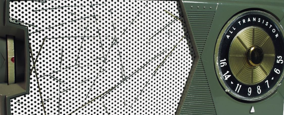
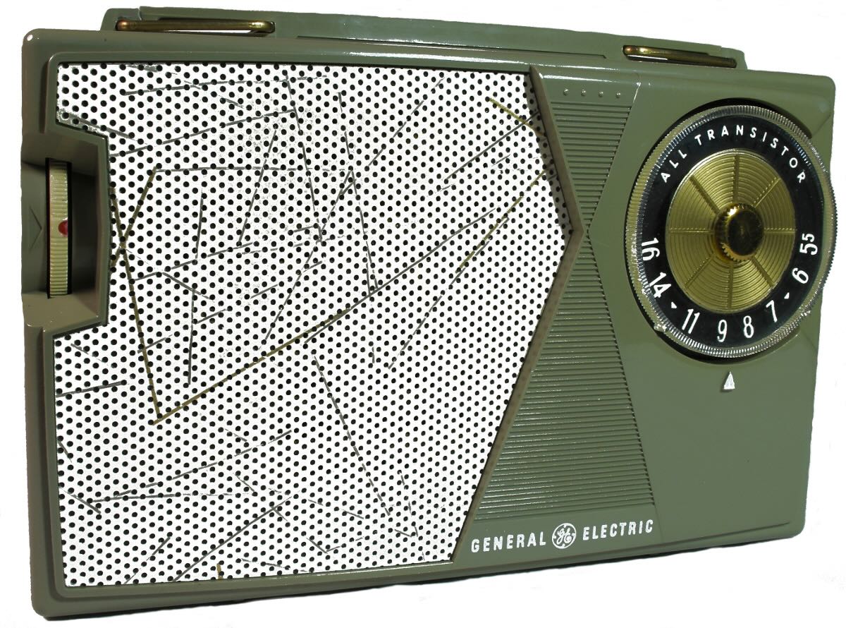
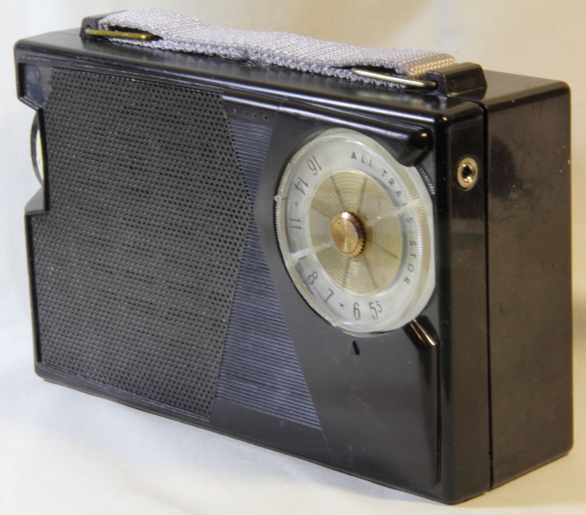
A few years ago, my thoughts went back to a particular old transistor radio belonging to my father. Well, technically it was my father’s, but I could use it, and it was certainly a seed for getting us both interested in radio as time progressed. The radio is of no distinction. It cost $20 in 1958 (nearly $200 in today’s money). It was made by General Electric, and is only known today by its model number, P755A. Despite its anonymity, I remember the radio as being uncommonly sensitive and selective considering its simplicity. It matched or exceeded anything we had in the house, all the samples of which were likewise of no distinction.
A Portable Radio
To appreciate portable transistor radios, it is necessary to understand what defined portable in the vacuum tube era. They were big and clunky. They ran off a special set of vacuum tubes which had low-voltage filaments or heaters. Separate batteries ran the filaments, “A,” and high-voltage screen and plate circuits, “B.” They consumed a lot of power, thereby draining the batteries quickly. In short, they were a somewhat compact descendent of early radios, which required no hookup to the power mains.
Early transistor radios were manufactured on the cusp of transistor technology. The Regency TR-1 was the first commercially manufactured transistor radio in 1954. All the large, established manufacturers, including GE, followed soon after. The P755A is truly a portable radio. First, there is no provision for running it on external power. Instead, a large, now-obsolescent, 9-volt, zinc-manganese dioxide (Zn/MnO2) battery was used. This single power source had the logistical advantage over A and B batteries, and would keep a P755A running continuously for more than five days – weeks or months of normal use.
Second, there was no provision for connecting an external antenna. Signals were picked up with an internal 6 ¼” ferrite, tuned loop antenna. Ferrite was also a relatively new application to radios. Its high permeability made it significantly smaller than air-core loop antennas attached to the backs of many tube radios. The radio did come with a single, somewhat obtrusive “earbud.” Volume and tuning knobs were all you got in the way of controls. In summary, the radio was a modestly sized independent package. Let’s call it the tablet computer or smart phone of its day. You surfed the dial to get sports, news, music, and weather, and everyone would soon have one.
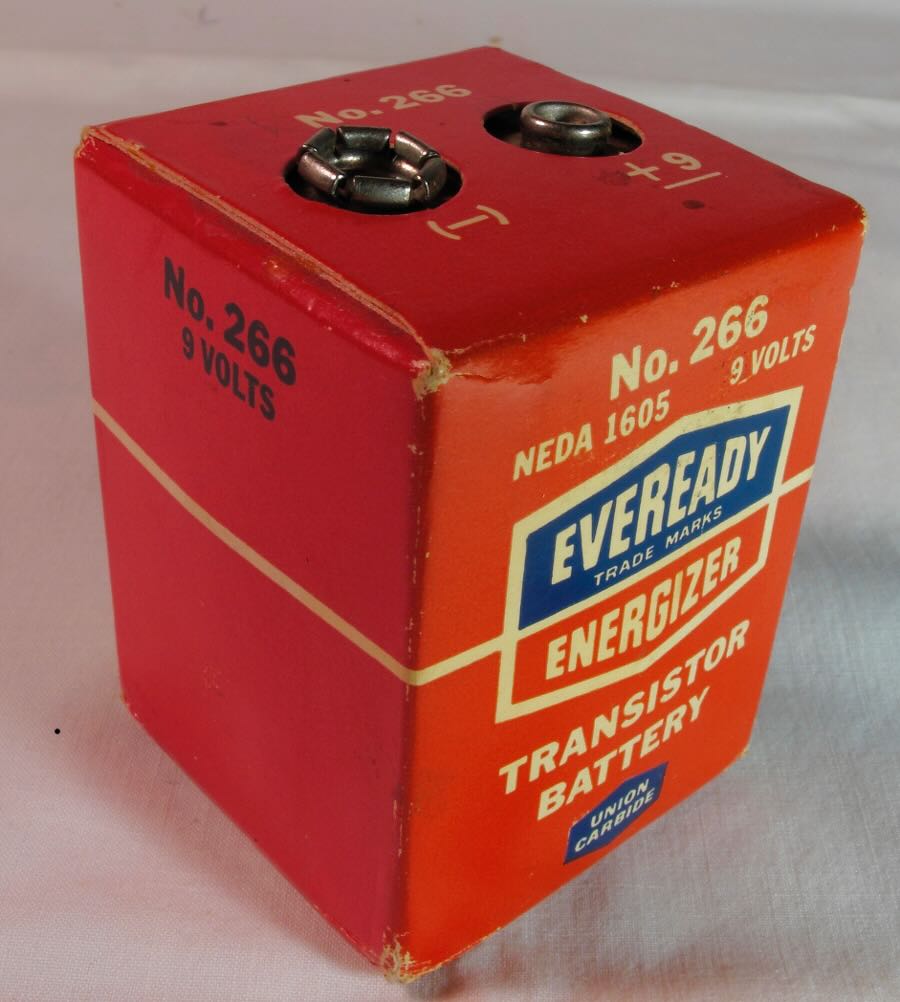
The 9-Volt Eveready No. 266 was one of at least three NEDA 1605 standard batteries, and had large contact snaps.
The Specialist
Somewhere along the way, the P755A got away from us, but over the years with the coming and going of many better communication receivers in my possession I never forgot it. So, it was a few years back that I happened to come across one on the Internet and recalled how I used ours for AM DX in the late ‘50s and early ‘60s. Further investigation on eBay indicated that, despite the protestations of many of the sellers, P755As and their near cousins were not all that rare.
At that point, my penchant for tinkering was once again aroused, and to date I have collected three P755As and another 15 (yes, fifteen) of its first cousins, P805A, P806A, P807A and P808A, which mainly differ in color. The selection of the P755A, besides being nostalgic, turned out to be quite fortunate.
- The radios are easy to work on. They can easily be disassembled and reassembled. There is a single PC board with separate, discreet components. Parts lists and schematics are readily available.
- The radios are cheap. An eBay transaction can often be made for $20 to $30, shipping included.
- The radios are powered by a single common voltage, i.e., 9 Vdc. This is very important as transistor radio designs of the pioneer era often ran on non-standard voltages, and some required two voltages. More on this later.
- The radio is AM only. The design isn’t compromised by switching AM and FM circuits in an out. That’s what I’m interested in – simplicity.
- Finally, being solid state, they run on very low power, thus presenting less danger to the not so punctilious tinker or the innocent radio.
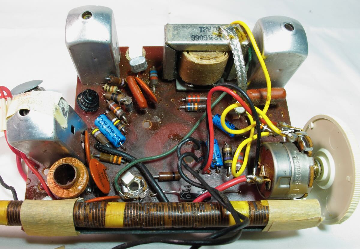
It is interesting to note in the case of the P755A and its cousins, that many of the components, including variable capacitor, volume control, and IF and audio output transformers were overly large and could have been found in vacuum tube radios of the time. These components were soon downsized to produce a later generation of “pocket” radios. Thus, the P755A, although entirely solid state, is something of a transitional radio.
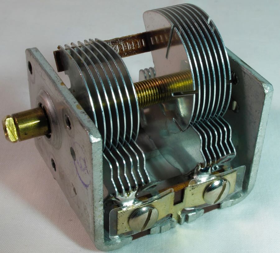
The robust metal frame variable cap used in these radios was typical of virtually all vacuum tube radios of the time.
The circuit board shown below is only missing connection to its variable capacitor, speaker, and battery to come to life. Having discreet components is a great advantage to the tinker. Note the large IF cans, audio transformer, and volume control. The parts layout wasn’t especially neat; it was function over form.
Germanium Transistors
A few orders to Mouser and eBay provided most of the necessary bits and pieces to make these units operational. But the downside of working on these radios today is that they are of the germanium transistor era. The industry soon made the transition to silicon as a key element in manufacturing. Germanium transistors, when you can find them now, are old stock and somewhat expensive. Fortunately, I have found only two or three defective transistors. It is possible to substitute silicon for a germanium transistor, but this generally involves trial and error rebiasing to control the gain. One intrepid experimenter I encountered in my travels had successfully managed to repopulate all five original germanium transistors with silicon. He concluded that it was an interesting experiment, but there was, at the end, no noticeable improvement.
Electrolytic Capacitors
One standard practice for most tinkers of old radios is the replacement of electrolytic capacitors, which tend to dry up and fail with age and disuse. Although some tinkers replace all electrolytics as a matter of course, I have always been of the conviction that ‘if it ain’t broke, don’t fix it.’ However, in the case of these old radios, replacement of all electrolytics is a necessity, as they have a very high rate of failure. In many cases, their replacement is all that’s required to restore the radio to operation. My theory is that in the early days of transistors, there was still not yet great demand for low-voltage, high-capacity electrolytic capacitors, and the material science of the day may not have been up to the challenge the changeover was requiring.
Repair, Modernization, and Restoration
I once worked for an Air Force sergeant who was the proud owner of a Ford Model A pickup truck in pristine condition. He told me that, although only a single taillight was required in the 1930s when the truck was new, he had added a second light on the passenger side as a safety feature, and that this was considered by serious antique restorers an acceptable deviation from the original. Repair, modernization, and restoration have long been conundrums for serious tinkers, including radio tinkers. Precisely, where do you stop with your tinkering?
The pièce de résistance, the holy grail if you will, is a radio restored to the operational and cosmetic point just as it came out of the box. The process of getting it there is filled with a myriad of stumbling blocks and likely more than a few compromises. The ultimate success depends a lot on the radio’s condition when you get it. Is it potentially redeemable, or is it a partially decomposed hulk? Many hopeless cases are quickly “parted out” in the parlance of the hobby. The problem is many of the parts that fail or become damaged are the same from unit to unit, and parted units will not always be useful.
My collection of P755As and cousins has arrived in cosmetic conditions varying from very good to poor. Being relatively small and rugged, the circuits have aged well, even in relatively hostile environments, and I have been able to restore all of them to full operation. So, to date there are no parts units. Cabinets were cleaned and polished. In a few cases of well-used, battle-scared units, missing handles and damaged speaker grills have been “fixed” to a point where the radios are simply fully functional, if not very representative of the original product.
As an example, the old warrior shown below is a P807A, and was missing its plastic handle. The bright gold foil speaker grill was mangled, the tuning dial was cracked in half, and the cabinet showed signs of heavy use. Obviously, the radio had provided someone with many hours of hard, happy use. I like to imagine it having belonged to a house painter who carried it around from job to job and listened to Elvis and Bill Haley. Perhaps it fell off his scaffolding once or twice. It was finally consigned to a closet decades ago. Eventually, I patched up all the mechanical issues, and brought its circuits into full operation. The P807A sings happily in the choir once again.
Then there is the case of modernization – the auxiliary taillight I mentioned above. In the case of the P755A and its cousins, the NEDA No. 1605 standard battery has long since become obsolescent. Forget Eveready, Mallory and Burgess. It is possible to buy a new, aftermarket battery, but at a price half again as much as the original cost of the radio. There are two easy remedies, the first of which is to use a standard PP3 9-volt battery. These are much smaller than the original battery and don’t have as much capacity. The better choice is to install a 6-cell AA battery pack. Being alkaline technology, these will have the same capacity as the original somewhat larger zinc-manganese dioxide (Zn/MnO2) battery. The AAs with a plastic holder will fit neatly into the original battery compartment. In either case, the larger battery contact snaps must be replaced with a pair of smaller ones. That is one practical concession to modernity.
Finally, for radios in hopeless cosmetic condition, the pure and wholesome virtue of restoration can now be abandoned in good conscience and give way to “hot rodding.” In the case of the P807A, above, a transfer coil has been added to the ferrite antenna and terminated with a 1/8-inch phone jack on the cabinet. Then, connection of a suitable loop antenna, and the P807A is ready for the DXing drag strip. Sometimes I feel like Sid from Toy Story.
A Note on Alignment
My fascination with radio alignment began many years ago when I found a few loose screws in the bottom of the old family radio console chassis – my first SW radio. Needless to say, I was quite disappointed when my zealous tightening produced a very insensitive radio. I don’t remember just how I learned that the precise compression of trimmer capacitors was necessary for optimum results, but my education in both theory and practice progressed over the next several years to a point where I became a master at aligning SP-600s which have double-conversion IFs and no fewer than 48 adjustments in the RF section.
I told you all that to tell you this. The manufacturer’s alignment instructions for many small radios should not be followed if you want to optimize the radio’s performance. For reasons of economy, variable trimmers, padders and inductors used to bring a radio into alignment are more often left off of the All American Fives. Long story short, the difference between the oscillator and antenna circuits is not always the ubiquitous 455 kHz and there may not be a convenient way to change this, most commonly at the low end of the band. Consequently, as you move the dial across the band, there is a progressive lowering of sensitivity. However, by simply adjusting the IF transformers to peak noise response at the low end, a significant improvement can often be achieved. Generally, there is some adjustment possible at the high end, to compensate for the new IF frequency. Repeating the alignment procedure a few times will bring the radio into better-than-new performance. Such was my experience with the P755A.
The Wonder is not that They Work Well
The wonder of the P755A and its cousins is not that they work well, but rather that they work at all. First of all, transistor manufacturing was in its infancy when these radios were made, and as reported, began with the use of germanium as the primary material. Consequently, consistency was not what it would eventually become. Sams Photofact Notes for these radios reinforces my point. “Transistor circuit resistance not given (sic is not given on the schematic) because of the wide variation in internal transistor resistances.” [Source: Sams Photofact Folder, Set 447, Folder 6, Howard W. Sams & Co., Inc., Indianapolis, Indiana, June; 1959.] Further, for economy, the tolerance of resistors and capacitors used in these radios was very wide. Variations of 10 to 20 percent in resistors could understandably have a significant impact on the operating range of a transistor. Again from Sams, “Nominal tolerance on component values makes possible a variation of ±15 percent in voltage and resistance readings.” As part of my restoration project, I collected point-by-point voltage and resistance-to-ground measurements on all 18 radios and found this to be the case. Notwithstanding, the radios all work well. Amazing.
Conclusion
Einstein is attributed as saying, “Insanity is doing the same thing over and over and expecting different results.” For my part, achieving the same results was exactly my objective, that is, to rescue a bunch of discarded, dysfunctional, old radios and restore them to operation. To use an old Chrysler Corporation slogan of the period, “Suddenly, it’s 1960.” It’s been fun.
The author is a mongrel tinker, having no pedigree, but giving assurances that no radios were harmed in the conduct of this project.
Postscript
It is hard for us living in an age of computers and the Internet to appreciate the fact that station information wasn’t always as easy to come by as it is now. Sixty years ago we relied almost entirely on printed media, mainly periodicals. Besides magazines, there were listener’s clubs such as the Newark News Radio Club and the National Radio Club, the latter still very much active today. They published monthly paper bulletins for members. Contributions of station information came from members. Volunteer editors laboriously prepared monthly columns on mimeograph stencils, which were then printed and distributed to members. But the comings and goings of broadcasting stations is a dynamic process, and each issue of these publications became less useful as time progressed.
In preparing this article on tinkering, I pulled out my very first medium wave station listing. Pictured below is the tattered, taped, and dog-eared copy of the Jones North American AM-FM-Radio-TV Station Listings, Winter 1958 Edition. It was an ever-present companion to our original GE P755A transistor radio.
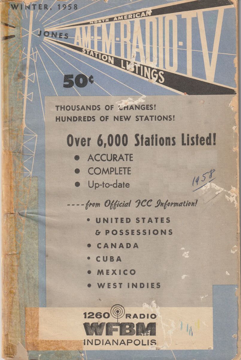
Beginning in the summer of 1958, for 50 cents you could get this neat little paperback book providing the call, location, frequency and power of 5,000 stations. Further, in an age before spreadsheets, the book was laboriously cross indexed by location, frequency, and call letters. The book was the passionate work of Vane A. Jones. It was initially compiled from what information he could glean from the FCC, in addition to questionnaires he sent out to stations requesting information. Not all stations responded, and those that did sometimes returned incomplete data. Nevertheless, Jones soldiered on using every resource available to produce what has been reputed by some as the most accurate listing of its time. The ambitious project which began as a quarterly publication was picked up by Howard W. Sams & Co. and continued periodic publication between 1963 and 1984 as the North American Radio-TV Station Guide under Mr. Jones’ authorship.
There’s lots more. For those who haven’t visited it yet, I recommend the World Radio History website, https://worldradiohistory.com/Radio_Log_Master_Page.htm. I would caution you however that it is addictive, and you can spend hours poking around the archives. There you will find an extensive trove of old books and publications, including the Jones Guide, White’s Radio Log, and past editions of the National Radio Club’s AM Radio Log, to mention a few.
Mr. Colegrove, all of us who read your article are indebted to you for both the content and clarity of expression in it. As one who has worked for almost half a century with the written word for a living, it was obvious that you spent a lot of time polishing it. Your dedication and respect for the radio hobby was evident and your care to explain it so well was nothing short of inspirational.
Thanks again.
Note that your radio has Civil Defense (CD) markers (small triangles) on 640 and 1240 kHz, evidence that the radio is circa 1953 – 1963. That’s where you’d listen in the event of a national emergency.
Thank you for the excellent article.
I remember the early ‘point contact transistors’ that would fail to work on a cold day.
Great article! I noticed that on medium and long waves it is best to listen to programs on old receivers.
I am amazed at the detail in this post. I too “tinkered” many times thanks to the prowess of my older brother and seeing him open a radio cabinet to connect a phonograph to its speaker. After that it was messing with “anything that moved” inside a number of receivers. I also had a GE portable, probaby the 807J. It was rendered obsolete when the volume potentiometer failed. Growing up in the shadow of 4 of the 6 local AM stations in my town, reception was no issue except when I wanted to hear 50,000 watt WKBW from nearby Buffalo. Once the receiver failed, no amount of “tinkering” by my 12-year old self could resurrect it but it led me to a million “why” questions anytime I ran into many of the people I knew in broadcasting. My curiosity continues on-and its origination started the same way Mr. Colegrove’s did-with results not nearly as impressive. Thanks for the article!
Good story – thanks for sharing, Bob! (and Thomas).
Vane Jones’ 1973 (or so) Station Guide was one of the first treasures I remember finding in the high school’s library once I got there in the mid-1970s. Years later, picked up what was surely one of the last c.1986.
As noted, all available online now and STILL worth looking through! 😀
I can’t find any personal information about Vane Jones on the Internet, as he has been gone for many years, although there are numerous citations for his book. I have a vague recollection that he was a real estate broker with an office in Indianapolis just a couple miles from where I grew up. His first love was that book, to the great benefit of his many readers. Indianapolis was also home to Regency and Howard Sams.
Bob C.