Category Archives: Antennas

The Great Gonzo Radio Experiment

By Jock Elliott, KB2GOM

It’s funny how you can start out thinking about how to solve a problem, the whole process takes a turn, and you wind up with an unexpected but pleasing result.

It all started innocently enough. Alan posted this — https://swling.com/blog/2024/11/bbc-rd-how-to-test-a-loop-antenna/ — and this statement appeared at the end of a BBC report on how to test loop antennas:

“Polarisation Illustrations of the antenna usually show it mounted upright; that is, with
its axis parallel to the ground. This is fine for the reception of LF and MF transmissions, which are vertically polarised, but most HF transmissions are horizontally polarised.”

When I tested that assertion here — https://swling.com/blog/2024/12/here-we-go-loop-de-loop-in-which-your-humble-correspondent-tests-a-hypothesis/ — there were a couple of interesting responses.

Bob Colegrove said (in part):

“To address your conundrum, from my long-standing, untutored tinkering with loop antennas, I have concluded that, regardless of LW, MW, or SW, optimum performance for peaks and nulls requires that the axis of the loop (i.e., line through the center of the coil) be able to rotate 360 degrees laterally and 90 degrees vertically.” (emphasis mine)

Robert Gulley added:

“I will have to concur with Bob – if I may state it another way, there is no “proper” position for a loop when getting shortwave signals.”

To which I responded:

“I suppose the ultimate setup might be an articulated motorized outdoor mount with a joystick inside that would allow me to fiddle the loop to the optimal position.”

Early in the morning I awoke thinking about how a system capable of manipulating my three-foot-diameter MFJ 1886 loop both vertically and horizontally might be implemented. Everything that came to mind seemed awkward, hard to put together, difficult to operate, expensive, and just plain clunky.

I dozed off and woke up thinking: “What about a really small loop? I could hold it in my hand and easily turn it to different positions to optimize reception, no equipment required.”

A thought came to mind: “You’ve got a small loop antenna, why don’t you see what you can do with it?”

At this point, I need to make my Shameful Admission: I got so intrigued by the idea of using my wrist and hand to turn a small loop to various orientations that I forgot that I was trying to solve the problem of manipulating a shortwave loop.

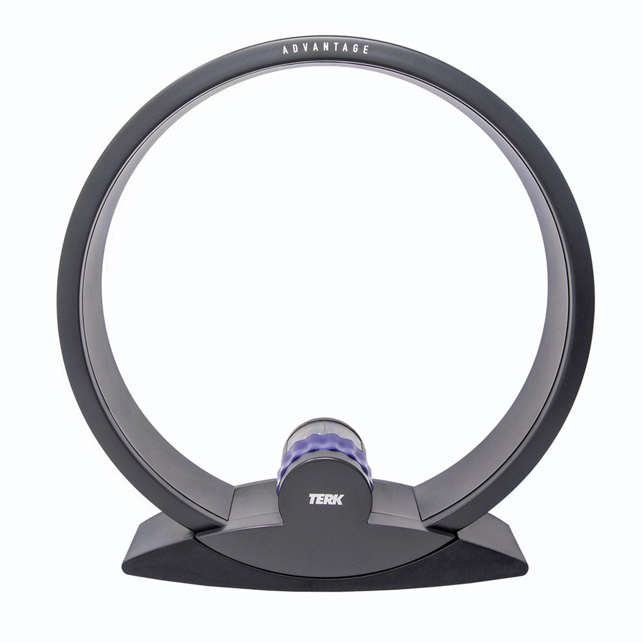
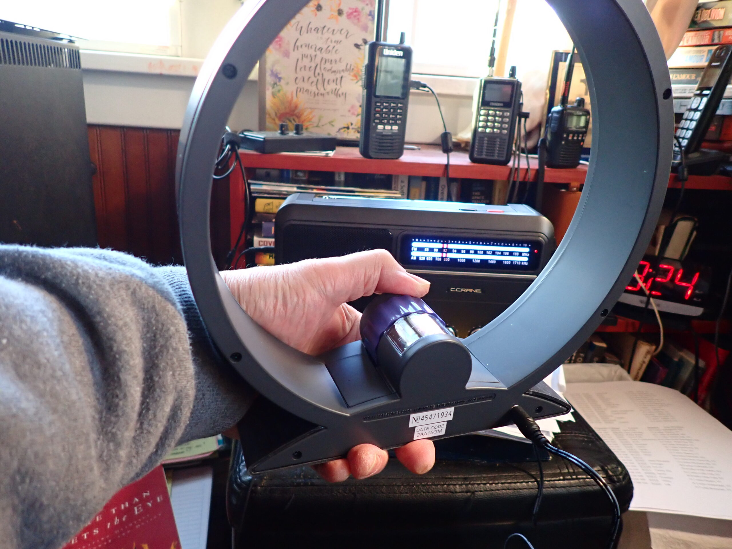
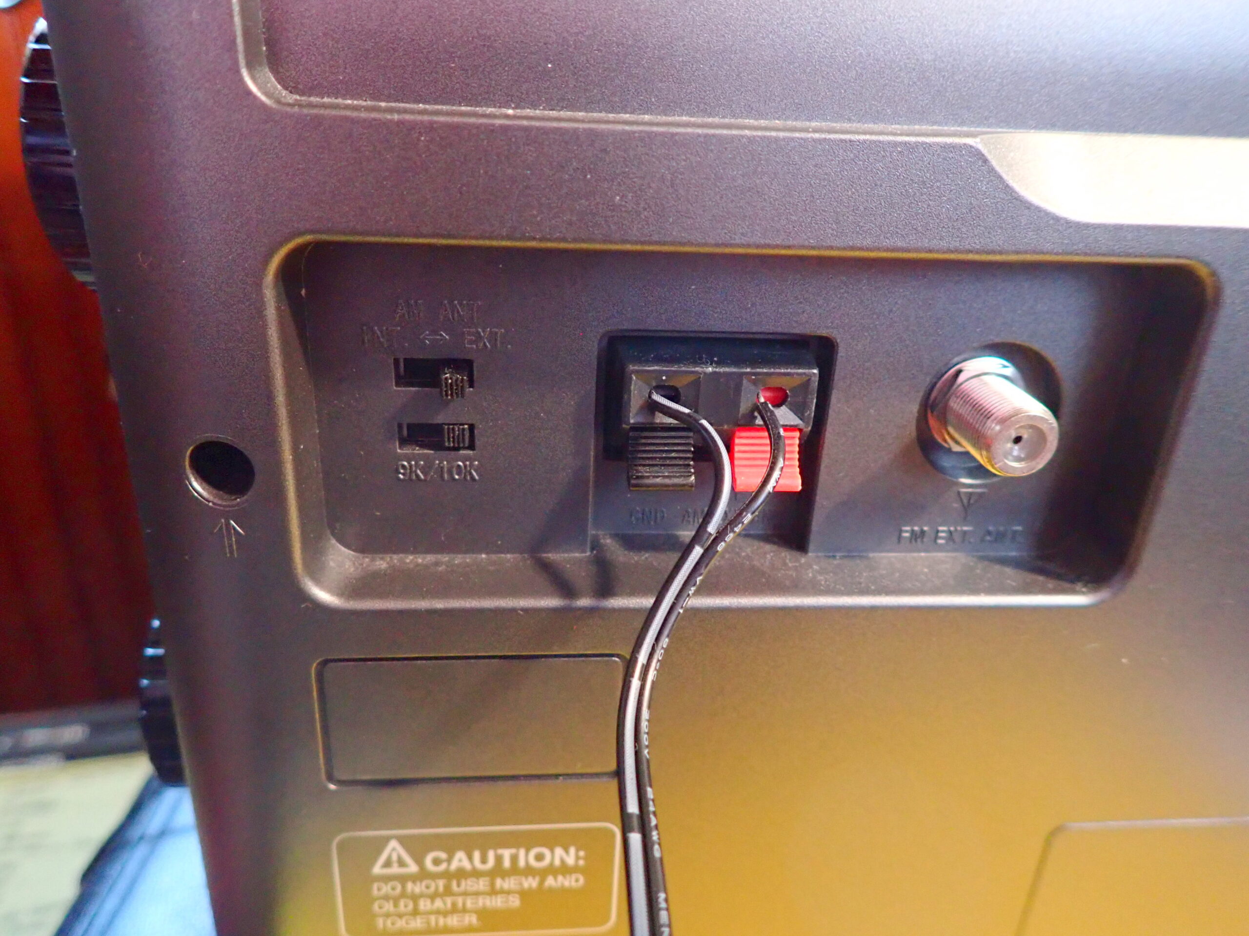
The loop that came to mind is the Terk AM Advantage. I tested it here.  Designed to boost signals on medium wave, it is a nine-inch tunable loop encased in plastic that requires no power supply. It inductively couples with the ferrite antenna inside a portable radio. But I seemed to recall that it also comes with a direct wire connector that can be used with some radios. Perhaps I could connect it to my CCrane EP-PRO which has clips and a switch for an external medium wave antenna on the back of the case.

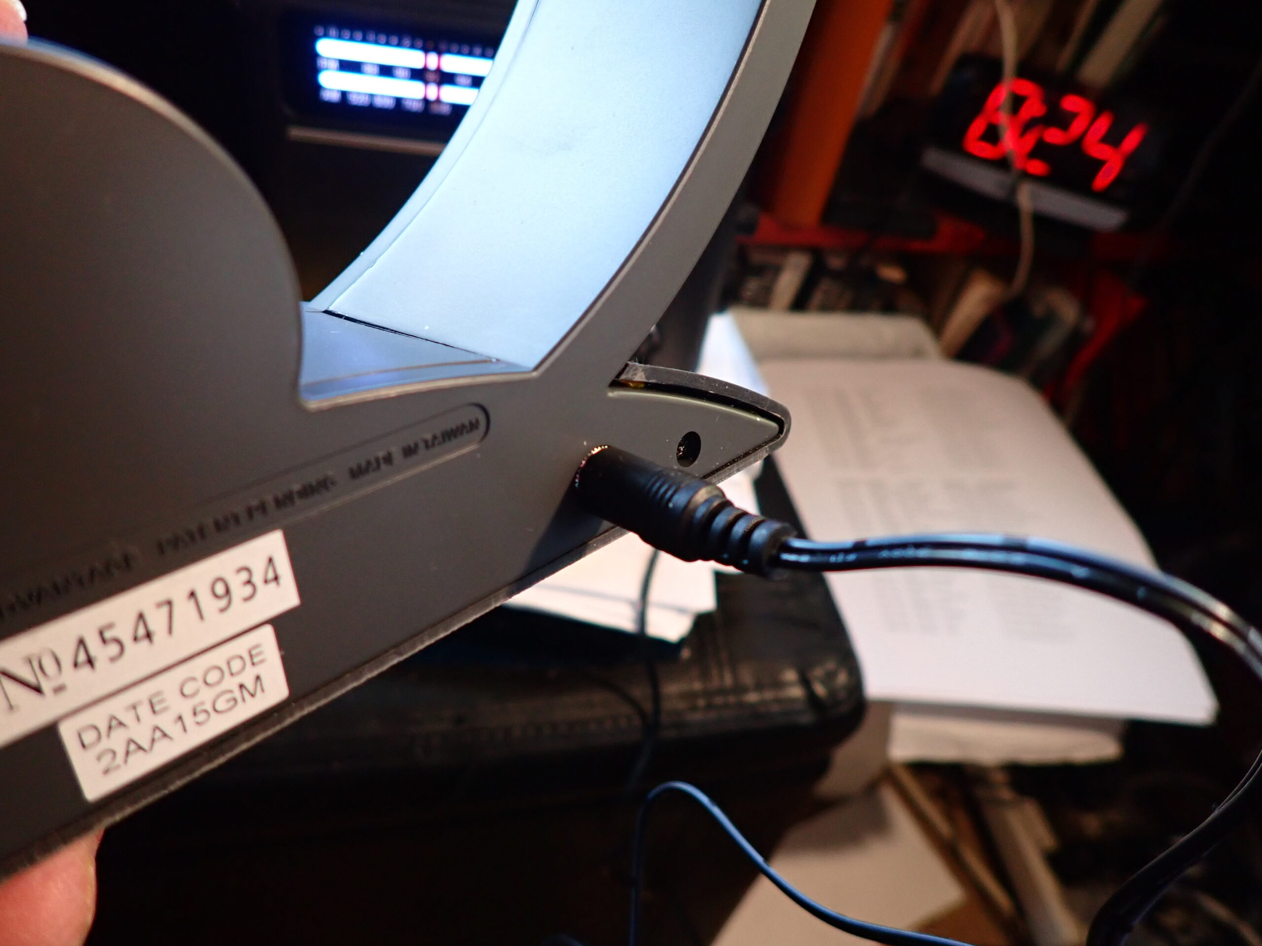
I found the Terk AM Advantage easily enough, but the direct wire connector required a major archeological dig. Once I unearthed it, I plugged the connector into the back of the Terk AM Advantage, slipped the wires from the connector into the clips on the back of the EP-PRO.

Now to try it out . . .

Tuning slowly down the dial, I found across a very faint signal that I could barely copy. Reaching around the back of the EP-PRO, I switched from the EP-PRO’s internal antenna to the Terk AM Advantage external loop antenna (which I was holding in my hand), rotated it from side to side, tipped it back and forth, and – tah-dah! – was rewarded by a far more copyable signal. It was WEEU in Reading PA, 200 miles away, transmitting 6,000 watts into the darkness on 830 kHz. Switching back to the EP-PRO’s internal antenna, I tried rotating the EP-PRO to optimize the signal but could not produce a signal that was as good as the external loop.

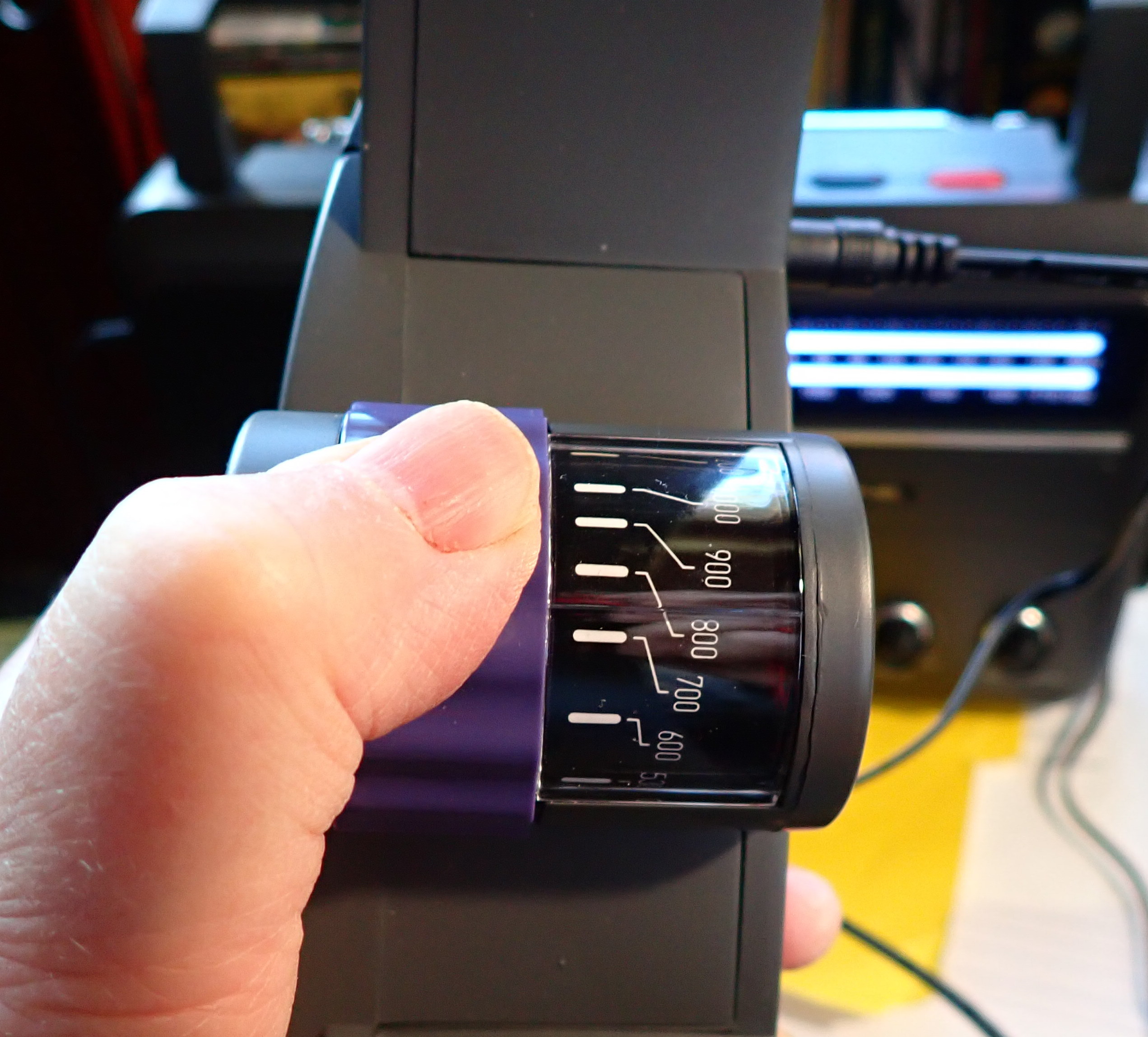
Repeating the procedure with additional faint stations, I got the same results: better reception with the handheld loop antenna, and it was fun and easy to use. I held it in my left hand (it’s light) so I could rotate the dial that peaks the signal with my thumb and working the tuning knob on the EP-PRO with my right hand. It was a very pleasing, almost addictive, experience.

If you’re looking for a potent setup for medium wave DXing, I can recommend the EP-PRO/Terk AM Advantage combo, even though it wasn’t my original objective. Call it serendipity.

In the meantime, does anyone know what might be the smallest loop that could be handheld for shortwave reception and would provide a performance boost over a whip antenna?

Here we go loop de loop . . . in which your humble correspondent tests a hypothesis

By Jock Elliott, KB2GOM

It was this post by Alan — https://swling.com/blog/2024/11/bbc-rd-how-to-test-a-loop-antenna/ — that set me off. After downloading the BBC report on how to test a loop antenna, I noticed the following in it:

“Polarisation Illustrations of the antenna usually show it mounted upright; that is, with
its axis parallel to the ground. This is fine for the reception of LF and MF transmissions, which
are vertically polarised, but most HF transmissions are horizontally polarised.”

Huh, I thought, “I wonder this would have any bearing on how I use my MFJ 1886 loop antenna?

So hooking the 1886 loop to an SDRplay RSPdx, here’s what the spectrum looks like on medium wave in vertical orientation with the 1886’s internal amp turned on:

And here’s what the medium wave spectrum looks like with the loop in horizontal orientation, amp on:

But what about shortwave reception? Here’s 31 meters in vertical orientation:

And here’s 31 meters with the loop in horizontal orientation:

Here’s 25 meters in vertical orientation:

Here’s 25 meters in horizontal orientation:

It looks to me, at the very least, the noise floor is lower . . . or I am in desperate need of a laxative?

For more about my adventures with the 1886 loop, check this — https://swling.com/blog/2022/10/testing-the-mfj-1886-receive-loop-antenna/ — and this — https://swling.com/blog/2023/01/saturday-morning-fun-fat-mw-dxing-with-the-mfj-1886/

My conclusions: I definitely don’t want the 1886 loop in horizontal orientation for medium wave DXing, but I think that the flat orientation might help for shortwave DXing.

What do you think?

Compact Antenna, Big Results: Giuseppe’s DICA 2 Redesign

Many thanks to SWLing Post contributor Giuseppe Morlè, who writes:

Dear Thomas and Friends of the SWLing Post,

I am Giuseppe Morlè, IZ0GZW, writing to you from Formia, in central Italy, on the Tyrrhenian Sea.

Do you remember the DICA 2 antenna? It was a small, shortened antenna with three ferrite cores inside, capable of tuning across all shortwave bands. Unfortunately, it no longer exists in its original form.

I have completely reworked the windings to enable the ferrites to also function for medium wave (MW) reception. Now, the antenna features:
• 35 turns for medium waves,
• 4 turns for shortwaves, and
• the same variable capacitor of over 1000 pF remains in use.

For medium waves, the antenna works wonderfully by induction. You simply place the ferrite core near the tube and turn the variable capacitor to achieve perfect tuning across the entire MW range.

I was genuinely amazed by its performance on shortwaves. Despite its small size, the antenna provides excellent gain, especially when a ground cable is connected to the variable capacitor’s casing.

I conducted several tests on my balcony. Initially, I thought the random ground wire simply improved the rotor’s tuning capability, but I discovered the antenna works equally well even when placed on a metal surface.

During a recent outing to Monte Orlando Park in Gaeta, I observed how the ground cable significantly enhanced both the signal strength and audio modulation. You can see this in my latest video, where I received Australian operators Greg and Grant on 20 meters with excellent signals.

The antenna’s two windings are separated and connected to the stator and rotor of the variable capacitor. On one end of the shortwave winding (the 4 turns), I’ve added a crocodile clip that can be attached or detached to switch between shortwave and medium wave operation. All of this functionality is achieved with a single variable capacitor.

I will soon share videos demonstrating all of these details and performances.

Thank you, Thomas, for your incredible activations—I follow them regularly on your channel, and they are a constant source of inspiration for me.

Greetings to you and all the Friends of SWLing Post!

73,
Giuseppe Morlè, IZ0GZW

Videos:

Pavel’s Practical Electronics Homebrew Mediumwave Ferrite Antenna

Many thanks to SWLing Post contributor, Pavel Kraus, who shares the following guest post:


Mediumwave Ferrite Antenna

by Pavel Kraus

This antenna for MW was made according to the instructions from Everyday Practical Electronics magazine, September 2000. The author of the Active Ferrite Loop Aerial construction project is Raymond Haigh.

The antenna was only adjusted mechanically according to my capabilities. Reception on this antenna was tested with receivers Malahite DSP 2 – original, Belka, Qodosen DX 286, AOR 7030+, Eton E1 XM and other receivers. Of course, the antenna does not replace a long wire antenna, but in limited urban conditions its performance is sufficient. I compared the antenna to Garry Thomas’ factory Quantum Loop.

Both antennas work similarly, Quantum Loop has a shielded ferrite rod, it is less susceptible to elmg. interference. Raymond Haigh’s antenna shows a bit more gain, the ferrite antenna is made up of 7 pieces of ferrite rods 20 cm long and 1 cm in diameter. The antenna is not shielded.

The construction of the antenna according to the instructions is not difficult. A Raimond Haigh antenna will definitely improve MW reception, especially for radios without an internal ferrite antenna. Instructions can be found at https://www.worldradiohistory.com/UK/Practical-Electronics/00s/Everyday-Practical-Electronics-2000-09.pdf

Belka Test

https://www.youtube.com/watch?v=Yk-ngCQ8TFc

Qodosen DX286 Test

https://www.youtube.com/watch?v=F77HOJSmu_4

Malahite DSP2 Test

https://www.youtube.com/watch?v=C2dvaCT9z6Y

Giuseppe’s “Delicate” Loop Antenna

Many thanks to SWLing Post contributor, Giuseppe Morlè (IZ0GZW), who writes:

Dear Thomas,

I am Giuseppe Morlè, IZ0GZW, from Formia, located in central Italy along the Tyrrhenian Sea. I hope everything is going well for you after the hurricane and that you and your loved ones are in good health.

I’m sending you this latest loop antenna of mine, which I’ve named “Delicate” due to its small size—about 20 cm in diameter—and because it fits perfectly with the Malahit receiver inside my car.

I am currently comparing it with a larger loop antenna inside the car to see how they differ. In fact, all of my antennas—whether for VHF/UHF or CB—are installed inside the passenger compartment of my car, and I can assure you, they work very well. Even my antennas for HF listening are mounted inside the vehicle.

I also have a loaded wire antenna hidden under the car, running from one wheel to the other. It works especially well on the 20-meter band, which is my favorite band for listening.

I wanted to share with you and all of the SWLing Post readers my experiences with listening and QRP experiments.

Thanks to you and all the friends at the SWLing Post.

Best regards,
Giuseppe Morlè, IZ0GZW

Dale Recomends the Aziloop DF-72 Antenna System

Many thanks to SWLing Post contributor, Dale Parfitt, who writes:

I wanted to mention a receive only antenna that I am using at my home QTH. I do a lot of NDB logging during the winter below 500kHz, some AM band DXing and 160M. In the past I have had Beverages, homebrew Flag antennas, Shared Apex Loop Array and now last month I installed the new Quiet Radio AziLoop:

https://www.quietradio.co.uk/

With the Array Solutions Model AS-SAL, I could electrically rotate in 45 degree increments and also flip the direction by 180 or make it bidirectional. Click here to download the manual (PDF).

You can read the features of the AziLoop on Dave’s site. But the outstanding feature is rotating electrically every 5 degrees and 2 modes- small RX loop and K9AY. In K9AY mode I can achieve up to 30dB F/B and the rear null is very sharp. If it did not rotate in 5 degree increments, you would not even see the rear nulls.

But here is where it really stands out. The K9AY design, like the flags and Ewes, has a terminating resistance. By varying the value of that resistance via the AziLoop App, one can achieve skywave nulls. The value of that terminating resistance changes from day to night etc. So using that feature, I can often reduce co-channel or adjacent channel QRM or thunderstorm QRN. Small loops (aka magnetic loops) cannot do that. They are omnidirectional to skywaves.

Anyway, I mention this as some of your site readers both ham and SWL might find it interesting.

I built mine from telescoping fiberglass poles and it is completely standalone- no loops on the ground stakes etc.

I have no commercial relationship with Quiet Radio- just a very satisfied client.

Thank you for sharing this, Dale. I was not aware of the Aziloop. Fascinating!

DICA 2: “The Revenge” – Giuseppe tests his updated homebrew antenna!

Many thanks to SWLing Post contributor, Giuseppe Morlè, who shares the following antenna project:

Dear Thomas and Friends of the SWLing Post,

I’m Giuseppe Morlè from Formia, central Italy on the Tyrrhenian Sea.

After the DICA prototype I created another one called DICA 2 The Revenge!

This other minimal antenna works differently from the prototype. It is shorter, has 3, 12 cm ferrites inside and has the sensors soldered inside in reverse on the telephone cable strap. It works coupled to a metal surface because it uses magnetic induction unlike the prototype.

In the videos you can see the differences between the prototype and the DICA 2…
and the yield on the highest ranges.

This small minimal antenna can tune listening from 3.5 to 30 MHz.

Thanks to you and greetings to all the Friends of SWLing Post.

73.

Videos