[Note: This procedure was updated and simplified by Guillermo on 22 December 2017]
Many thanks to SWLing Post contributor, Guillermo, who writes:
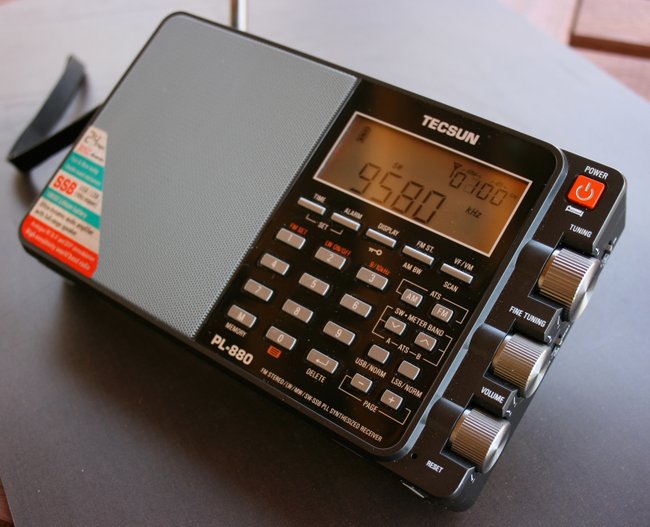
I own the PL-880 and just discovered a new feature : a 1.0 kHz bandwidth mode on shortwave (SW only not in MW).
The procedure to get it is as follows:
- Turn on the radio and tune any frecuency on SW . There is no need to connect or disconnect an external antenna and turn on or off the radio during this procedure.
- Be sure that on SW the 4 button feature(press 4 for about 2 seconds) is ON and 9 button feature(press 9 for about 2 seconds) indicates a value of 13 or more and not less than 10.
- Then turn OFF 4 button feature and then ON again . Press BW button and see the 1.0khz new BW on the screen. Now you can use it permanently on SW and ALSO on MW , UNTIL you press BW button again .
Well, I hope you understand this description–if not please let me know, and tell me if it works on your unit, or it is just works on mine.
Thank you, Guillermo! I see where this is somewhat of a fragile adjustment in that a number of actions could change the bandwidth back to a previous setting, but nonetheless is quite a fascinating hack/hidden feature! Thank you and I’ll add this to our list of PL-880 hidden features.
Post readers: please comment if you can successfully enable the 1.0 kHz bandwidth on your unit. Please comment with your radio’s manufacture or purchase date if possible.