 Many thanks to SWLing Post contributor, Bob Colegrove, who shares the following guest post:
The Tecsun PL-990/PL-990x as an MP3 Player, Bluetooth Receiver, and PC Speaker
By Bob Colegrove
Source: PL-990x Operation Manual
Sometimes after a medium wave or shortwave DX session I just like to kick back and listen to good music. Perhaps this is an age-related malady. I recently did a scan of the FM band and came up with 60 listenable stations in my area. By listenable, I only mean they can be received clearly. In practice, I only listen to a couple stations. Although, my tastes in music are quite varied, apparently, they do not coincide very well with local FM broadcast station formats. No matter, I can still indulge myself listening to diverse favored artists.
The Tecsun PL-990/990x offers a ready solution having both an MP3 player and Bluetooth connectivity. Actually, there are several compatible audio formats available on the player, but for simplicity I will merely refer to them as MP3. I really didn’t buy this radio purposely for these additional features. I bought it as a follow-on to the PL-880, which I still like very much for all its well-known features as a multiband radio.
I spent some time on the Internet reading all the reviews and watching many YouTube videos. Among useful things, I learned how to take the radio out of its box. The aggregate of all this information was thorough coverage of all the salient features of the 990 – all except the treatment of the MP3 player and Bluetooth connectivity. These generally appeared at the end of each review in a by-the-way fashion with little detail.
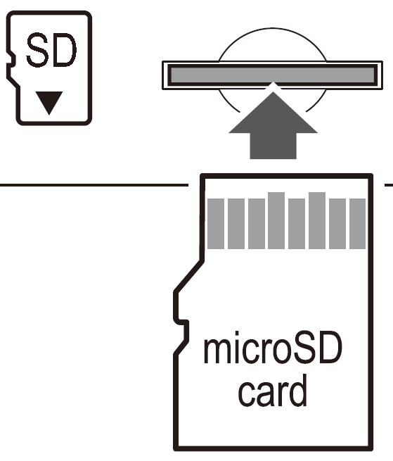
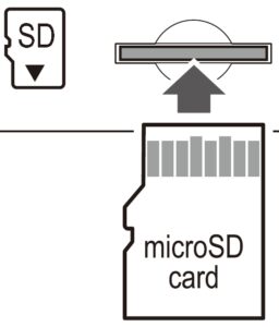
I bought a PL-990x with expectations that it would be a good radio performer, and that has proven to be the case. During its setup and checkout, I realized the potential for its MP3 and Bluetooth capabilities. A few years ago, I digitized all our vinyl recordings and cassette tapes, so I had many hours of material readily available for inclusion on a micro-SD card, which can be inserted on the bottom of the cabinet.
Source: PL-990x Operation Manual
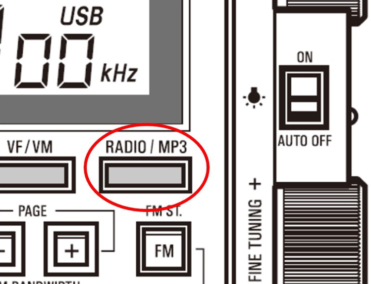
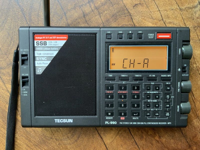
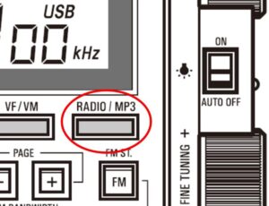
The radio, MP3 player, and Bluetooth modes are available by toggling a single switch.
Source: PL-990x Operation Manual
As an MP3 Player
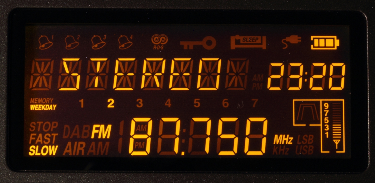
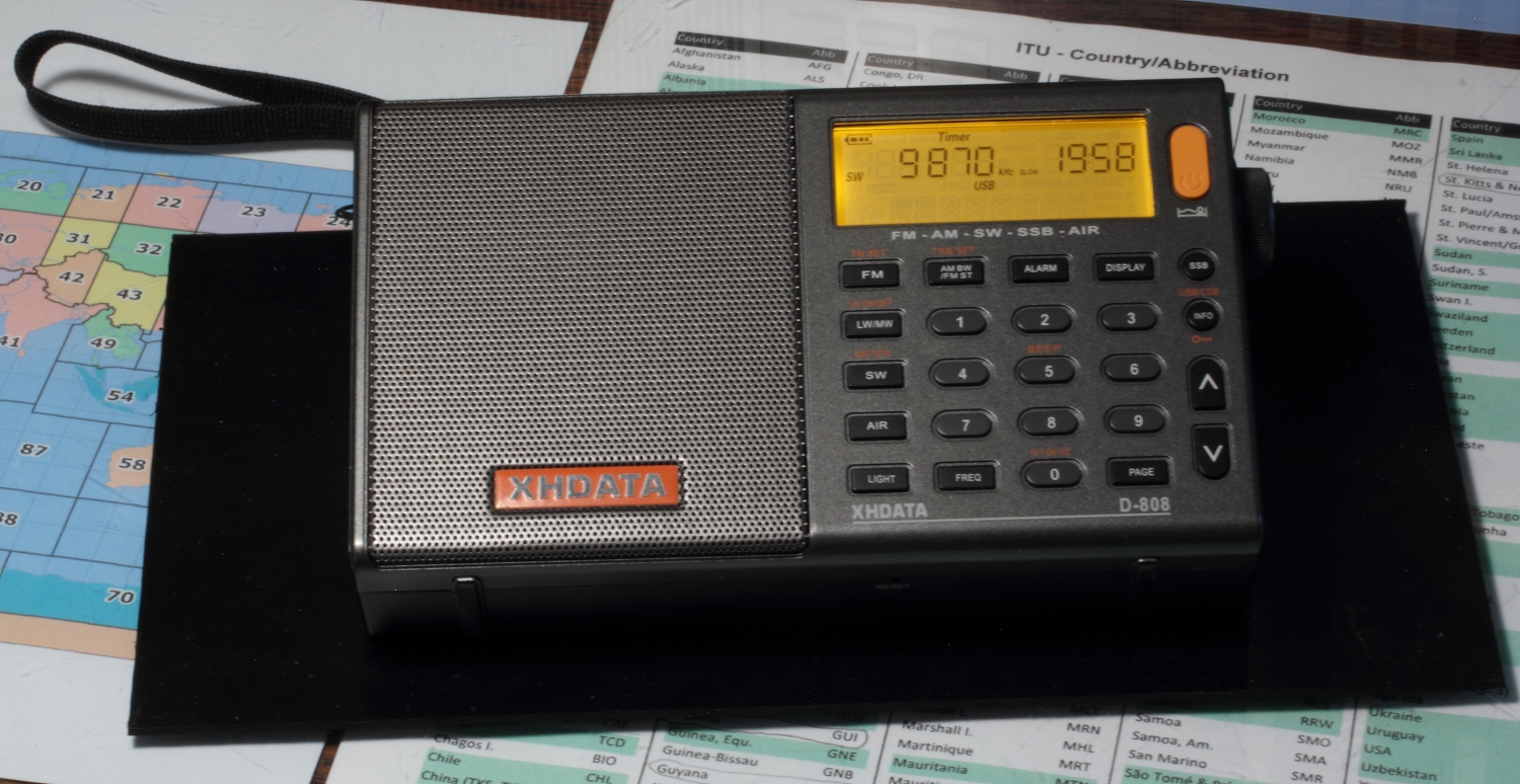
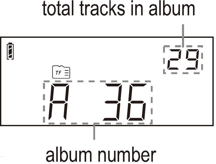
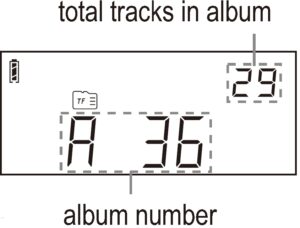
Unfortunately, the display does not have a multi-segment set of characters for text. This is the way random RDS information is displayed on radios such as the XHDATA D-808 and Eton Elite Executive. So, selecting albums and tracks on the 990 is limited to numeric representation, which doesn’t provide much of a clue identifying the musical selection. The user must either remember where favorite files are stored by number or keep some sort of number-title log.
Files are stored on a micro-SD card having up to 128 GB in capacity. That’s a lot of content. The radio comes with a 16-GB card, which will probably be large enough for many users. There are some details to consider when setting up the card. This information is lacking in the manual, but I have tried to fill in the blanks below.
Some rules:
1. There is no purpose in trying to alphabetize or otherwise edit album or track titles to locate them in a specific sequence. The 990 doesn’t understand this.
2. Generally, albums and tracks will be assigned numbers by the 990 in the order in which they are saved to the SD card by the computer.
3. Albums equal folders. Tracks equal (MP3) files within each folder. You can mix and match the content in albums and tracks any way you want to. It does not have to conform to the publisher’s album content.
Source: PL-990x Operation Manual
4. An album/folder can contain both its own tracks/files and nested folders containing other albums. A nested album/folder will be numbered in sequence after the containing folder. Any previously saved album/folders will be renumbered higher in sequence.
Rule 4 offers some flexibility. You can come back later and prioritize any album/folder by simply nesting it with another album/folder.
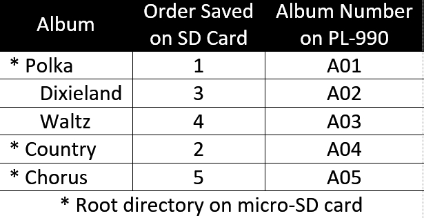
The table below is an example of five different musical genres compiled into separate albums. On the computer, the polka album was transferred to the SD card first, then classic country. At that point, the polka album was A01 and country A02 on the 990 display. Later, Dixieland and waltz albums were added to the tracks in the polka folder. They then became A02 and A03 respectively, and the country album advanced to A04. Finally, the chorus album was added in the root directory and became A05.
- The 990 recognizes the SD card quickly after it is inserted into its slot.
- The number of tracks and albums (files and folders) is only limited by the SD-card format, which for all practical purposes, won’t be a limitation. By way of example, I used the default exFAT format and loaded an album with 657 tracks; I don’t recommend that many.
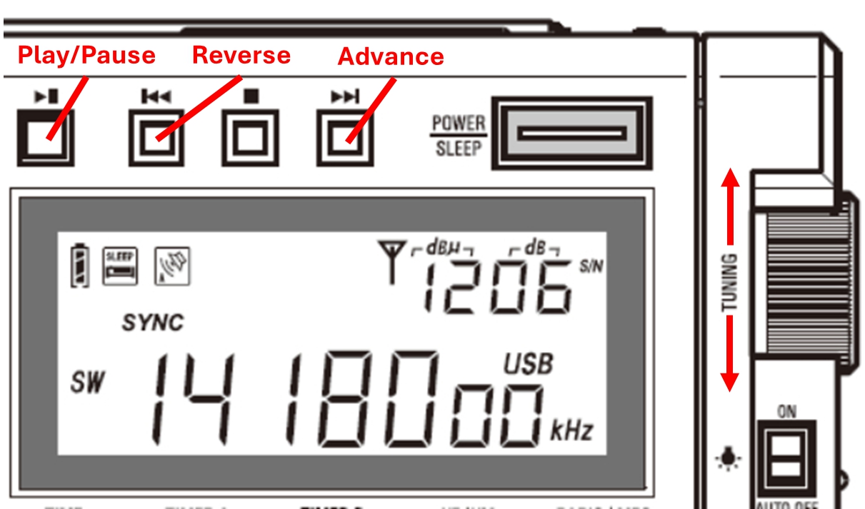
- A single track can be repeated by long-pressing the PLAY/PAUSE button.
- The tracks in an album will be repeated continuously.
- There does not appear to be a way to shuffle tracks.
I did encounter some difficulty with micro-SD card compatibility, which was independent of brand. A couple micro-SD cards were prepared on a computer using an adapter card and a micro-SD card reader and operated correctly in the computer, but the content was not recognized by the 990. I suspect this might be due to the early manufacture of the cards, but I’m not sure.
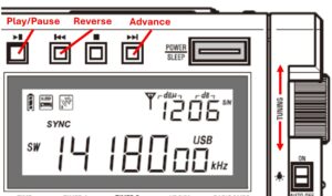
The 990 manual picks up the explanation from there describing operation of the control keys. I found it most convenient just to scroll through the albums with the FINE TUNING knob and through the tracks with the main TUNING knob. The number pad buttons will also work for direct album or track selection. Their application depends on the last tuning knob turned.
Bluetooth
Bluetooth is a hidden feature of the 990. Activation is partially covered on the hidden feature sheet.
- With the radio off, press and hold the PLAY/MP3 button. If OFF (for Bluetooth) appears in the display, press and hold the button again until ON appears in the display.
- Turn on the radio.
- Toggle the PLAY/MP3 button until “BT” appears in the display. The display will have a horizontal, animated dashed line for a few seconds, then it will change to an animated rectangle indicating that the Bluetooth feature is on.
- Follow the procedure for your tablet, computer or phone to pair the device with the 990. “Tecsun PL-990” should appear on the device as a choice for pairing. The 990 only pairs with one device at a time. If you have trouble, ensure that the 990 has not inadvertently paired with another device.
Bluetooth, of course, opens Internet streaming from a phone, tablet or computer. These ‘remotes’ have the convenience of full text capability and offer easier selection of content. I paired my PL-990x with a Kindle tablet; it has a range of at least 25 feet. The same micro-SD card could in theory be transferred from the radio to the tablet and function the same way. A smart phone would add cellular connectivity.
Control:
Three of the four player control buttons above the display are active in Bluetooth. The stop button has no effect. As with the MP3 player, the main TUNING and FINE TUNING knobs will also advance or reverse the track selection. Interestingly, this works with audio player apps as well as services such as YouTube, where it advances or reverses videos on the tablet, computer or phone. In addition to the RADIO/MP3 button, pressing any of the band buttons will immediately exit Bluetooth and tune to the selected radio band.
Source: PL-990x Operation Manual
In MP3 or Bluetooth mode, there is no noise from a USB wall wart. It might be a good time to charge the battery.
As a Computer Speaker
Finally, there is what the 990 manual calls the computer speaker mode. Sounds inconsequential. Why would anyone want to use a monaural radio on a computer that’s likely outfitted with stereo speakers? Actually, it’s more than that. By plugging your 990 into a USB port on your computer you have the normal charging feature, but you will also have complete USB connectivity with your PC.
Turn on the 990. You may have to press RADIO/MP3 button until “PC” appears in the PL-990 display.
- You will not be able to use the radio.
- The content of the micro-SD card in the 990 should appear as a USB drive in the computer’s file directory. You can transfer files on or off the 990, but the process will be very slow. Transfers from the computer to the 990-installed SD card follow the same rules listed above for the MP3 player.
- The computer will provide the MP3 play function through its own app. You can select files from either the 990 SD card or those on the PC and play them through the 990 speaker.
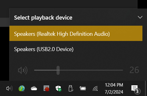
- You can switch speakers between the 990 or those on the computer by selecting the speaker icon on the computer task bar, then selecting the available speakers.
- The pause/play button on the player controls will work, but the reverse, stop, and advance buttons will not.
Final Thoughts
Some disappointment was registered in the reviews that the 990 does not have a recorder. Yes, this would have been nice. One thing it does have is a line out jack which has adjustable gain. This makes my outboard recorder much happier than when it is used with some other radios.
Since we are talking about audio, I have noted that some reviewers still prefer the sound of the PL-880. To my ears, the 990 sounds every bit as good. Remember, these are mid-size portable radios.
The inclusion of MP3 player and Bluetooth capabilities on the 990 adds very useful functionality to this radio. After nearly four years of consumer availability, I must wonder why they haven’t received more attention.