Tag Archives: Shortwave Transmitter Photos

Photo gallery of the Rampisham Down transmitting site in 2003

Many thanks to SWLing Post contributor, Dave Porter, who shares a link to the following site which contains an extensive galley of photos taken at the Rampisham HF transmitting site on October 11, 2003.

Click here to view the gallery.

Thank you for the tip, Dave!

Spread the radio love

Photo emerges of Droitwich mast and LF antenna

Many thanks to SWLing Post contributor, Dave Porter, who writes:

This picture [above] has just emerged, photographer unknown but most likely a rigger from the top of one of the 700′ masts there!

This was taken at Droitwich sometime after colour photography came in (late 1960’s) and before 1986 when the four wire Tee was replaced by a new design developed by BBC Antenna Engineer Tony Preedy, G3LNP that improved upon the 11-j85 Ohms driving point impedance giving a few more ohms and less capacitive reactance for the 2 x 250kW B6042 transmitters and a greater radiation efficiency.

Tony’s present LF array does not look so symmetrical as it comprises four separate Tee wires with the drops as a square box rather than the centre-joined drops of this one.

Tony also developed a low profile Tee antenna over 3 x 17m wooden telegraph poles for MF at up to 1 kW that was used when planning restrictions were enforced. Efficiencies were up to 40% at the 1500 kHz end of the band. However, if used by birds as an overnight roost it could provoke VSWR trips on solid state transmitters, the fix was to use a sliding reduced power detector that wound down the power to a level that did not trip the VSWR monitoring. Old tube transmitters were not affected!

The operating frequency for this LF Tee was 200 kHz at that time, now the antenna is on 198 kHz

Wow–thank you, Dave, for sharing this photo. We truly appreciate your impressive knowledge of UK broadcasting and history! And, wow! The views those riggers took in!

Spread the radio love

Example of a manual wavechange at BBC Skelton A Transmitter

By Michael Whitfield, CC BY-SA 2.0

Many thanks to SWLing Post contributor, Dave Porter (G4OYX), who shares the following:

Here’s Steve Gale in the late 80’s or early 90’s starting a wavechange on a Marconi BD272 250 kW sender at SKA.

There were eventually 11 of these senders at the BBC Skelton A site.

The first pic is the Final RF amplifier output stage with the 15/17 MHz coil being in situ. It sits between the two anodes of the output tubes.

Below the anode coil sits the coupling coil and it is on a motorised deck, that can be moved backwards and forwards on power to couple up to the required power output.

Steve is just starting the band change as he is wearing the leather gauntlets because after a transmission the coils are very hot.

Both the anode and coupling coils will be removed and replaced by those for the next required frequency.

A fifteen minute period was allocated by the BBC WS Schedule Department to accomplish a band change though two of us could do them in about eight minutes if pushed!

The picture below shows Steve starting to remove one of the pair of the 3-turn 40 kW Penultimate stage to Final stage coupling coils, again he is wearing the gauntlets. A different coil will be used for the next band.

The three turn coil covered 9, 11 and 15 MHz.

All those senders have gone now at Skelton.

Two are still in use at Woofferton and some in Singapore.

Thanks so much for sharing this glimpse into a working shortwave radio transmitting station, Dave! There’s nothing QRP about those transmitters and I bet those coils got incredibly hot!

Spread the radio love

Krasne Antenna Array: Help Rick solve a 22 year old mysetery

The mystery array

Many thanks to SWLing Post contributor, Rick Slobodian, who seeks help solving a 22 year old mystery. Rick writes:

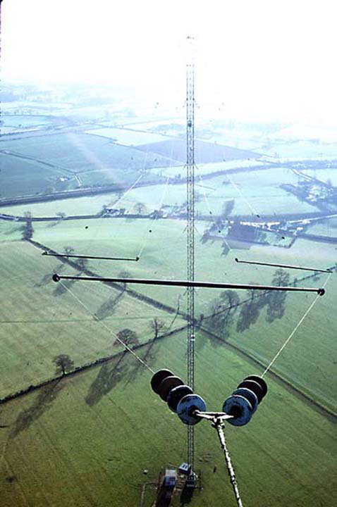
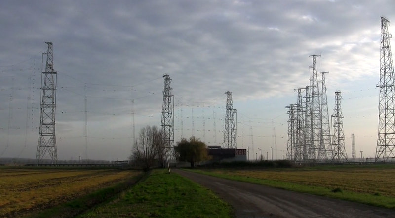
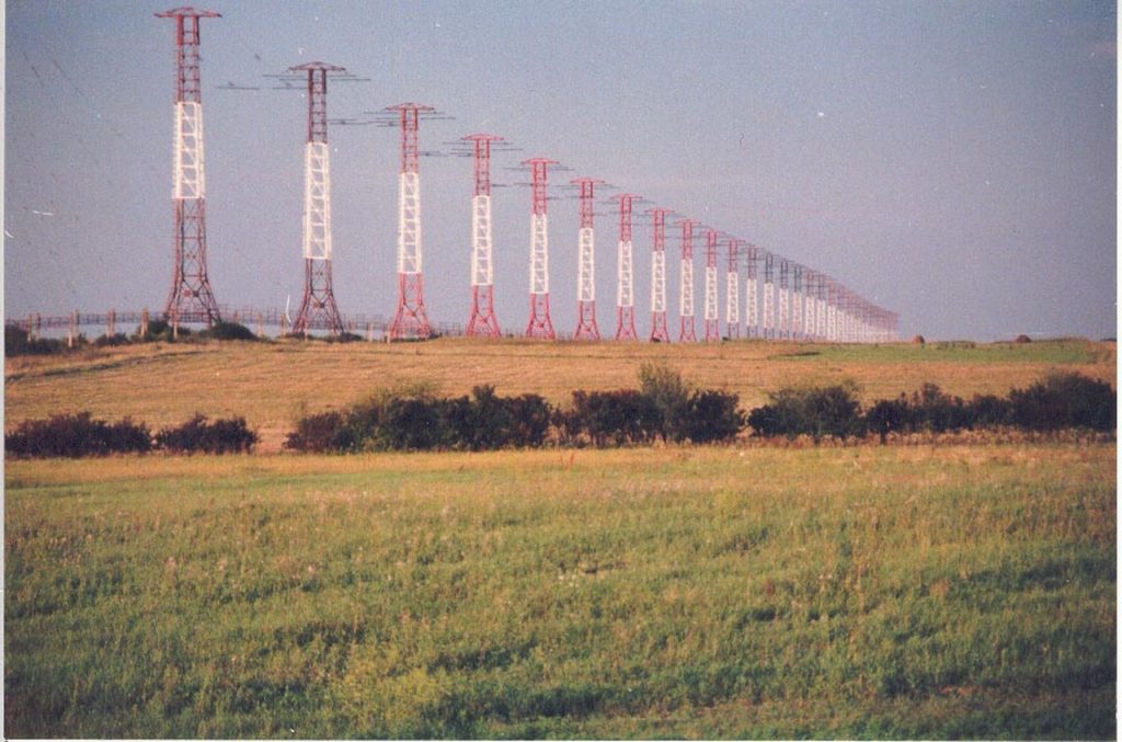
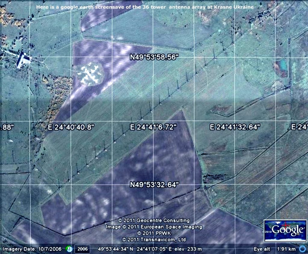
[Perhaps you can help me] explain this antenna….a 22 year old mystery antenna (see photo above)? What sort of antenna is this and how does it work? It’s at 49.8994 N 24.685 E near Krasne, Ukraine.

I was at this transmitter site in 1998.
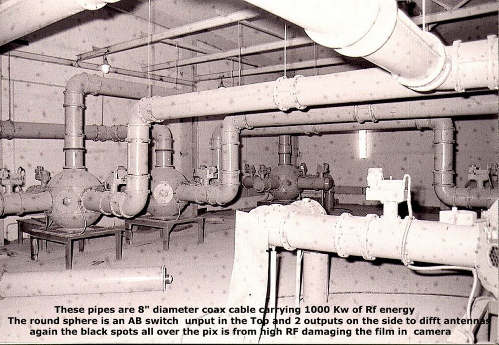
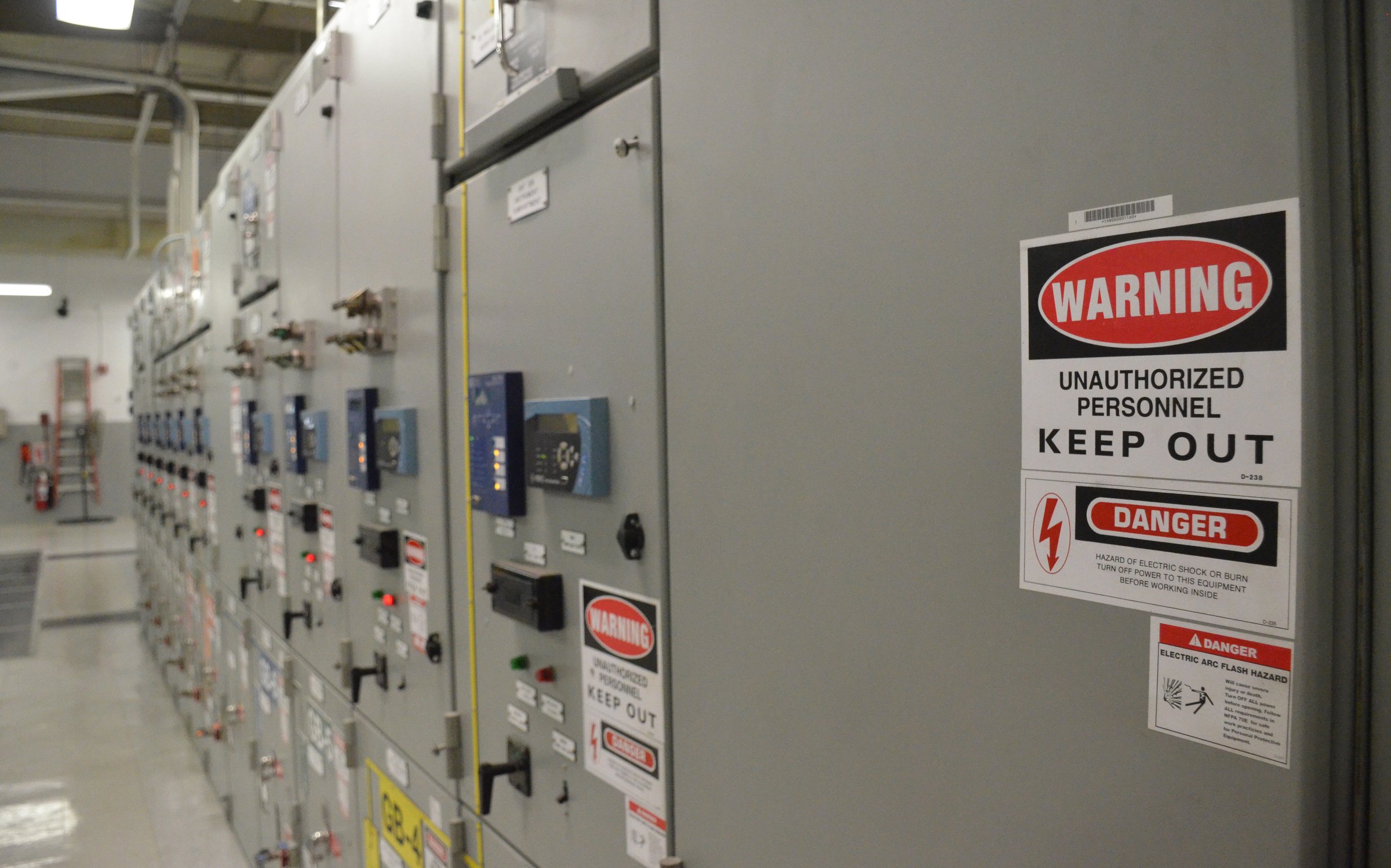
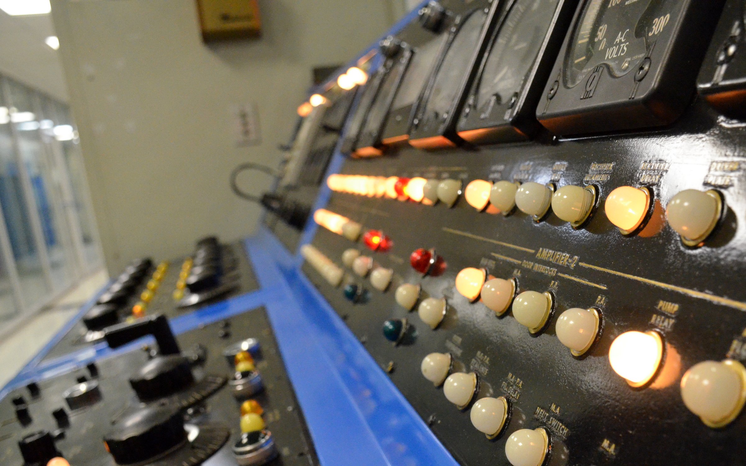
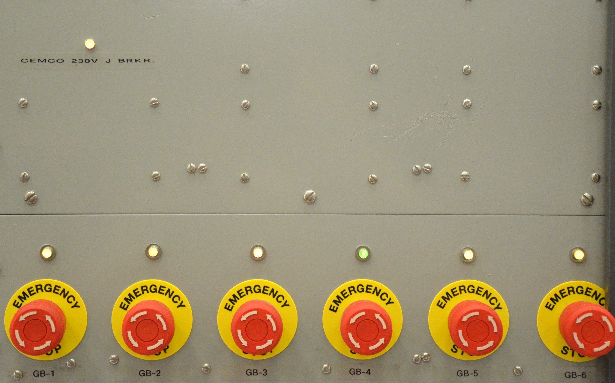
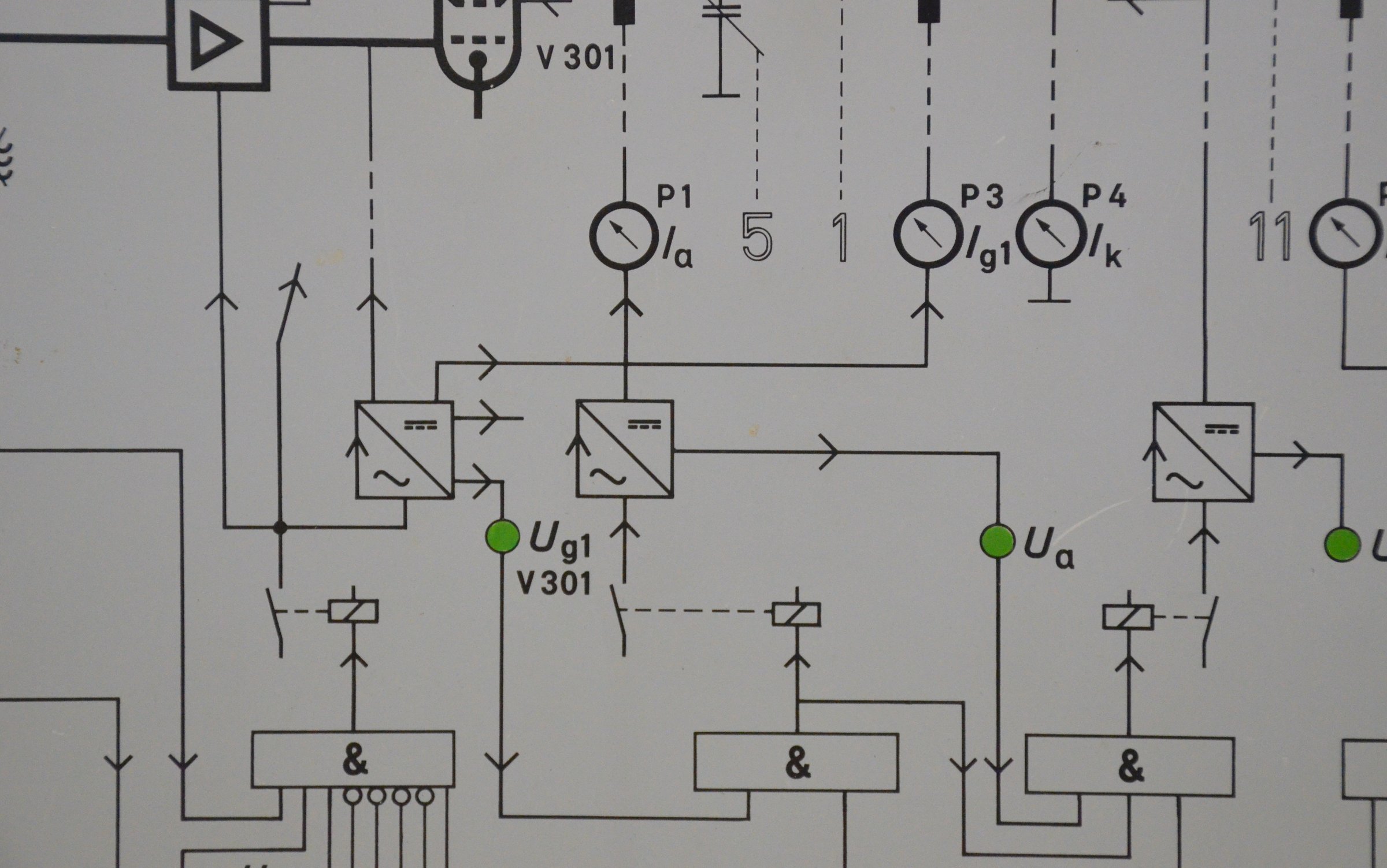
Antenna switch room

I was writing articles for a number of magazines hoping to find customers for airtime and to make this site viable.

I spent all day at the site wrote extensively about EVERYTHING ELSE: the shortwave transmitters, the longwave transmitters, the shortwave antennas, the vertical long wave antennas, and the vertical MW antennas.

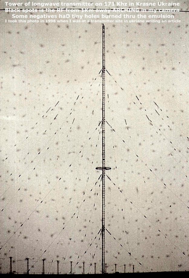
Longwave antenna at Krasne

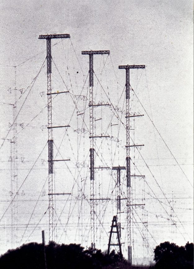
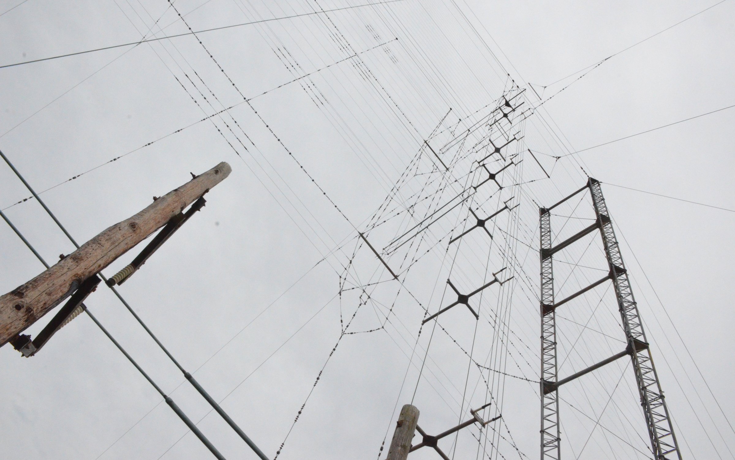
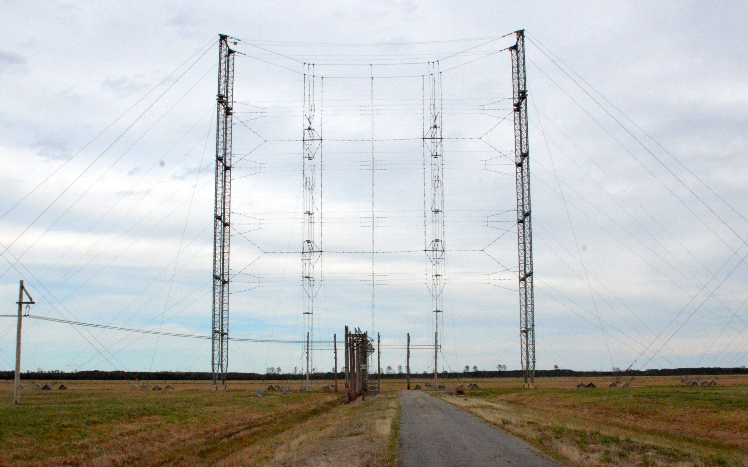
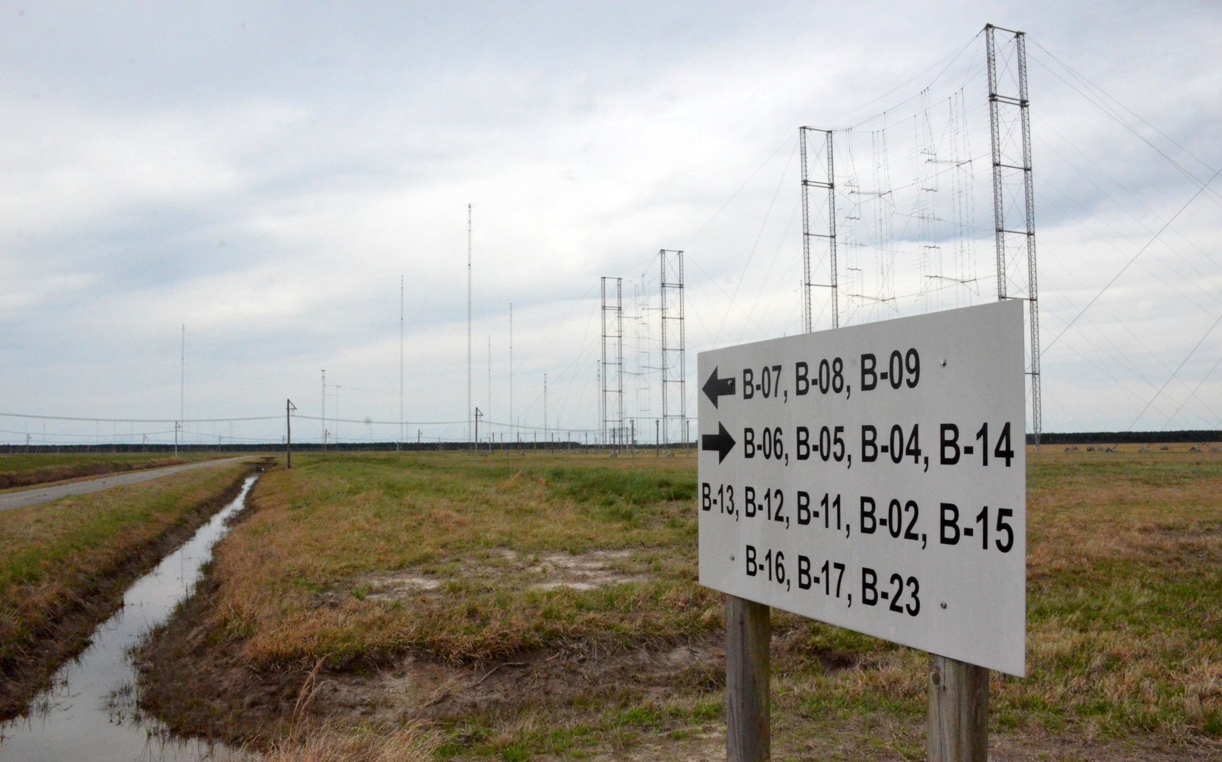
HRS curtain array at Krasne

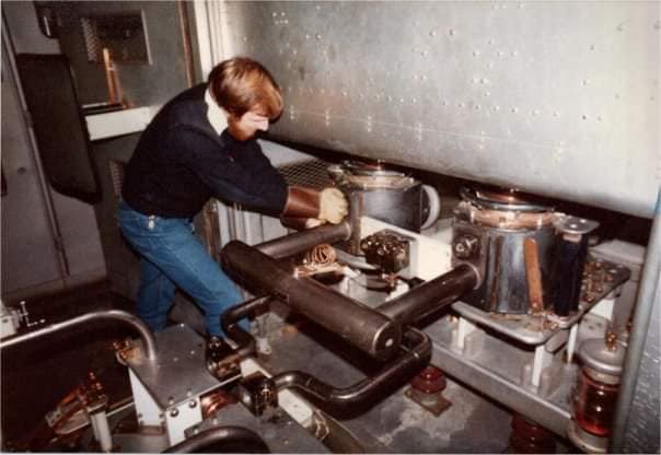
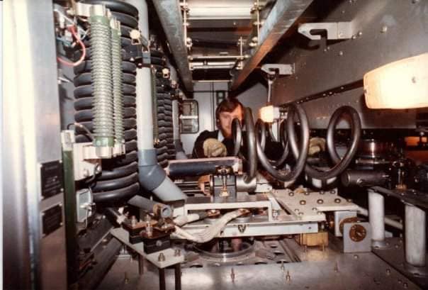
The transmitters were behemoths: Komintern Burans 500Kw 1000 Kw 1200 Kw

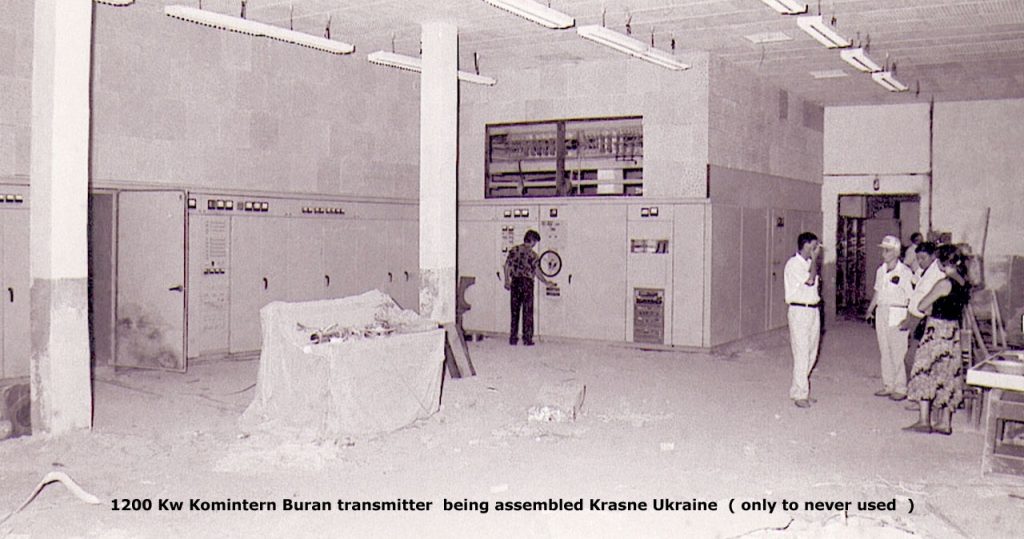
New 1200 Kw transmitter under construction

This antenna was over a km form the main building and they would let me go there:

I took this photo of the array as I traveled past it by train.

Its 36 towers strung in a NE SE line–over 2 km long and each tower is approximately 40 m tall.

[My hosts] were they so evasive about this antenna array yet not the rest of the site.

[There are some peculiarities:]

  1. Do you see a feed line running along the bottom of the towers near the ground?
  2. I do not see any tuning shacks.
  3. Is it fed from one end or the other end or is each tower fed?
  4. If each tower is fed, then where are the tuning shacks/phasors?
  5. iIf it is a beverage then why so may towers and such close spacing?
  6. Is it something completely different?

What do you think it is? How do you think it works and what would be its purpose?

Thanks for sharing, Rick!  My hope is that one of the members of the Post community may be able to shed a little light on this interesting antenna array.  Please comment!

Spread the radio love

RNW: Video of Flevoland Shortwave station

Screenshot from Peter Veenendaal’s video of the RNW Flevo shortwave station

Many thanks to SWLing Post contributor, Peter Veenendaal, who shares the following video and notes:

I am a former employee of Radio Netherlands Worldwide, which stopped broadcasting exactly 5 years ago next May.

Three years ago I made this short video of the Flevoland Shortwave station RNW used until 2007. It’s still there, idle and hoping for better times.

Click here to watch on Vimeo–All rights Peter Veenendaal.

Many thanks, Peter–most impressive! The magnitude of those curtain antennas is simply amazing. Thank you for sharing.

Spread the radio love

Edward R. Murrow Shortwave Transmitting Station: wallpaper images

VOA-site-B-Wallpaper-MainBuilding2

On April 1st, I spent the bulk of the day at the Edward R. Murrow Transmitting Station outside of Greenville, North Carolina. Prior to my visit, I asked if SWLing Post readers had any requests or questions I could address while there.

I printed all of your inquiries and made sure they were addressed during my visit. I also took a lot of photos!

I had hoped to have a post published the following week with all of the photos and responses properly curated, but frankly, I haven’t had the spare time to do it yet. I’ve simply had too much travel and too many projects on my plate since that site visit (not to mention cramming for the Extra exam!).

I’m working on a draft of the post now and Macon Dail (WB4PMQ), the transmitting station’s Chief Engineer, is helping me with captions and responding to your questions.

Wallpaper

One reader asked if I could snap some photos that could be used as wallpaper on his computer. This morning, I selected eleven images and cropped them to fit a widescreen monitor.

I tried to pick images that would work well as a background/wallpaper–meaning, they’re not too busy (visually). Some are abstract close-ups.

Click on any of the images on this page to enlarge–then simply save the image to your computer to use it as you see fit.

I hope you enjoy!

VOA-site-B-Wallpaper-MainBuilding VOA-site-B-Wallpaper-HighVoltage VOA-site-B-Wallpaper-Curtain-Closeup VOA-site-B-Wallpaper-Curtain-Antenna VOA-site-B-Wallpaper-Continental-Transmitter VOA-site-B-Wallpaper-BluePrints VOA-site-B-Wallpaper-AntennaFarm VOA-site-B-Wallpaper-Antenna VOA-site-B-Wallpaper-1 VOA-site-B-Wallpaper-TX-Mimic-Panel

Spread the radio love