So the SWLing Post has been online now for twelve years and during that time I’ve been accused of being a “radio enabler.” Of course, I’ve never counted just how many, but I’m guessing somewhere in the region of 115,900 times.
Truth is, radio love is infectious.
In the past, I’ve read reviews and articles about radios that have lead me down the path to making a purchase. Countless times.
Yesterday, though, I quite literally enabled myself.
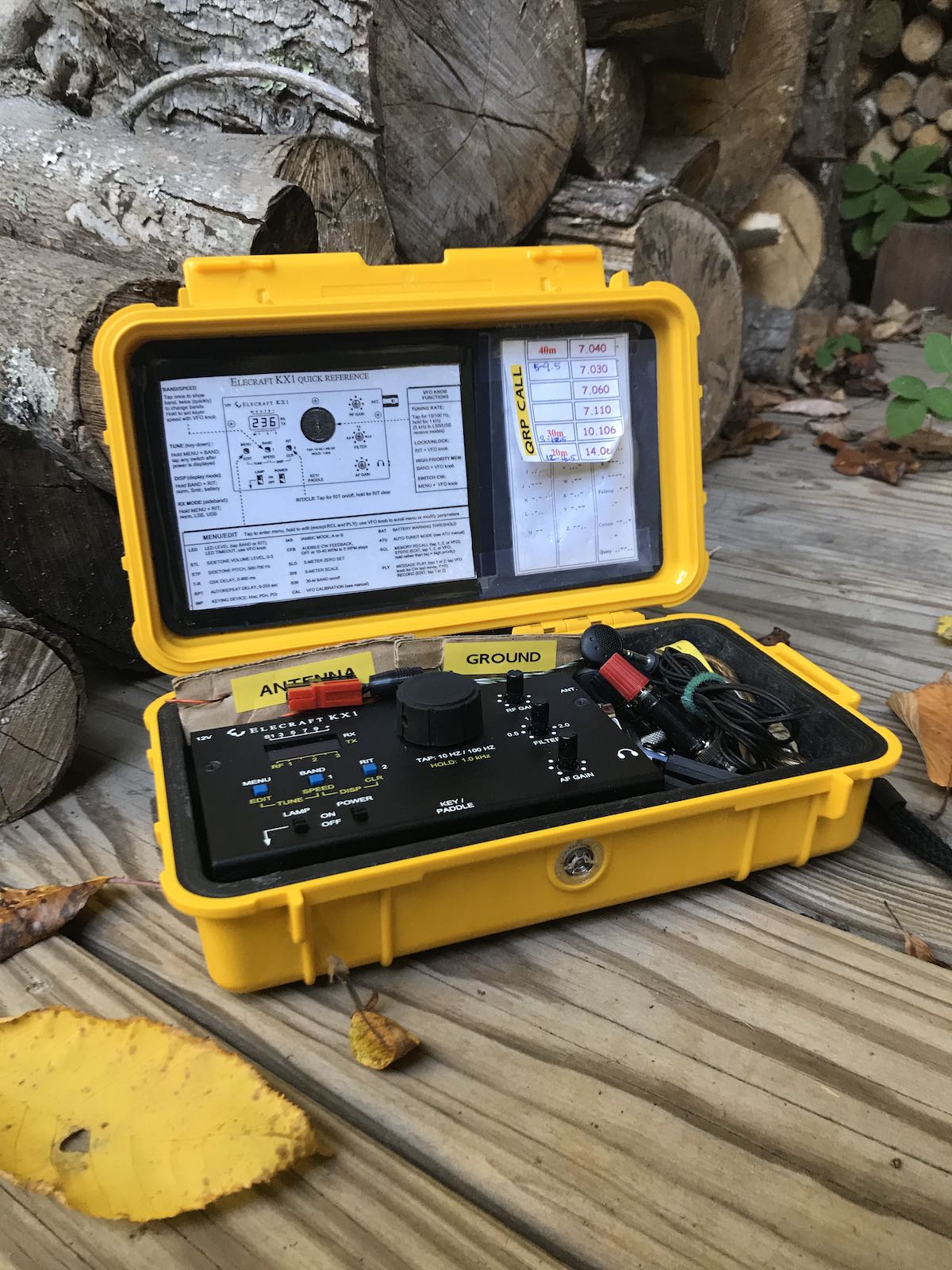
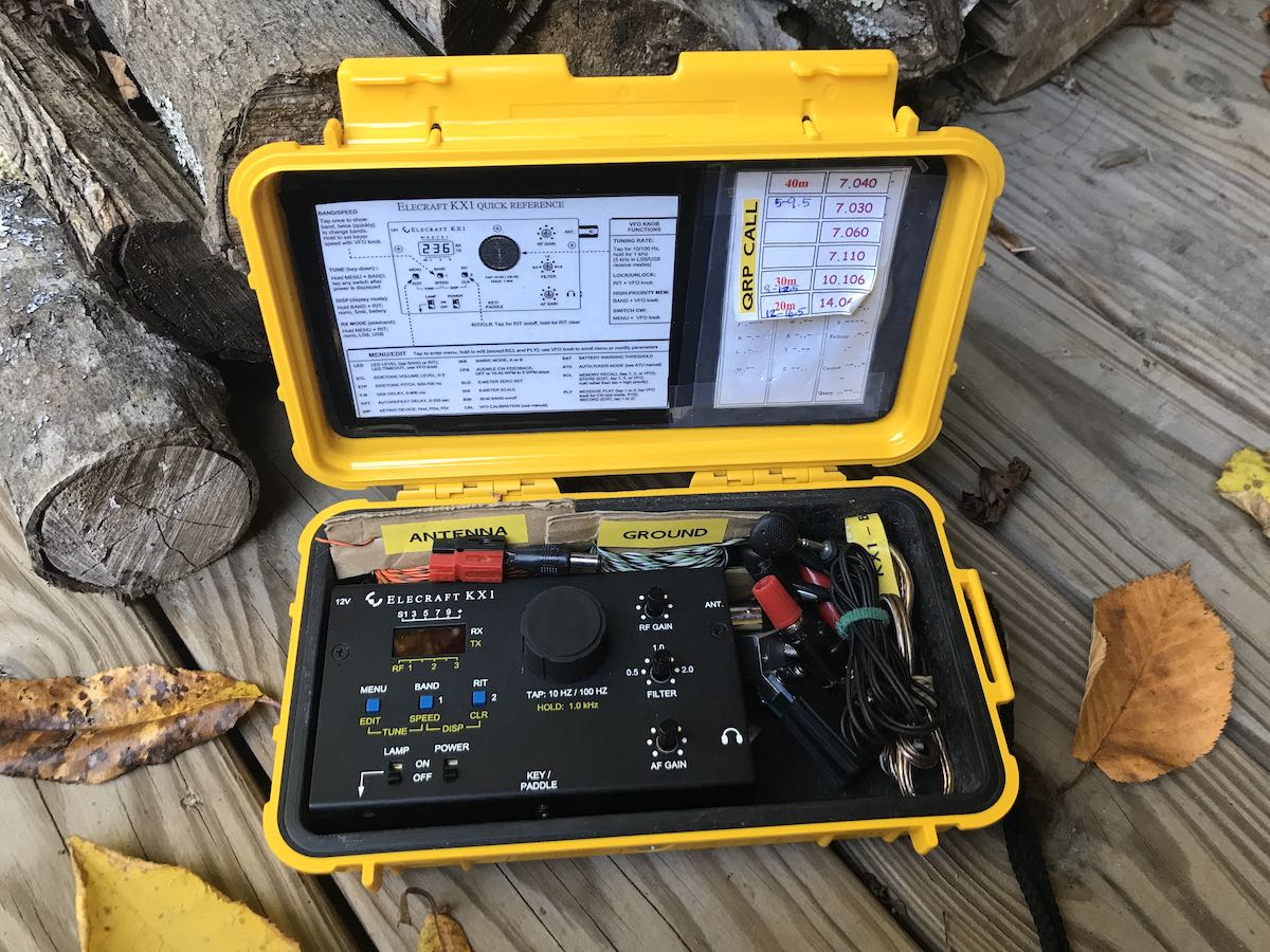
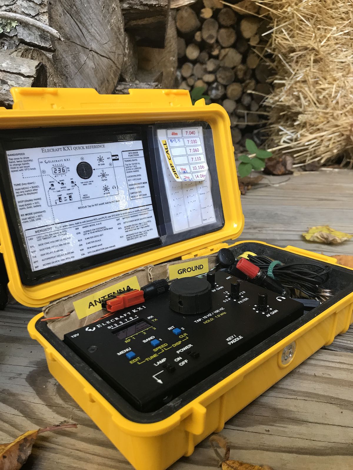
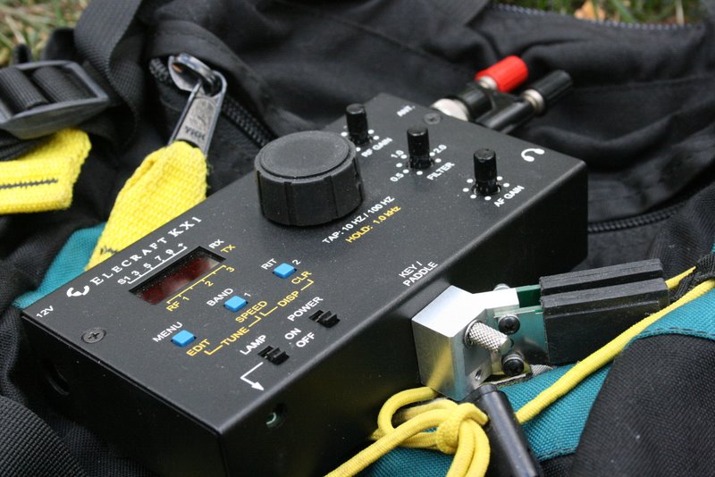
It all started with the Elecraft KX1
I posted this article on QRPer.com where I listed four ham radio transceivers I regretted selling. The number one pick was the Elecraft KX1 QRP CW transceiver.
I owned the KX1 for years. It was my first CW-only transceiver and my fist backpack-friendly radio for proper lightweight, low-impact, field radio fun. I sold it in 2016 to help fund the purchase of my Elecraft KX2.
Besides simply admiring a radio that embraced the philosophy of “form following function,” the KX1 had features you wouldn’t expect in a radio so compact and so lightweight. For example…
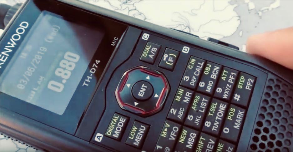
SWL Band RX
Wayne Burdick (N6KR)–co-founder and engineer/designer at Elecraft–is a shortwave radio enthusiast.
The KX1 was designed so that while you’re camping, hiking, or activating a SOTA site, you can also do a little SWLing!
Even though the KX1 is a CW-only rig in transmit, they added both LSB and USB out-of-band reception. Depending on the KX1 band configuration, you can zero-beat broadcasters, widen the adjustable filter, and enjoy shortwave listening in the field.
When I owned the KX1, I did this quite often. Don’t get wrong: it couldn’t compete with, say, a dedicated shortwave receiver like the Tecsun PL-680, but it worked well enough that listening to even weaker stations was very doable. When one-bag travelling or camping, it was great to have one radio that could serve two functions.
LED Log Book Lamp
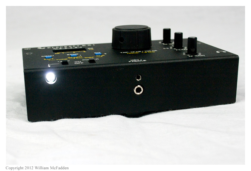
Photo: Eric (WD8RIF)
To my knowledge, the KX1 is the only portable transceiver I know of that includes a built-in logging lamp.
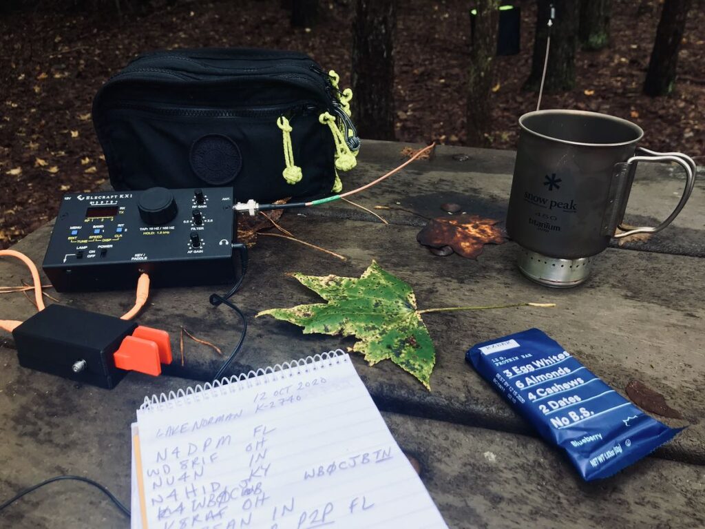
I remember once operating the KX1 on the beach at Jekyll Island, GA one evening and using the lamp to illuminate my logging sheet. Good times…
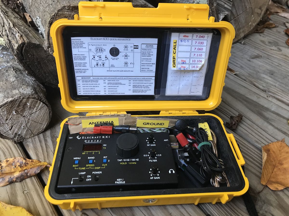
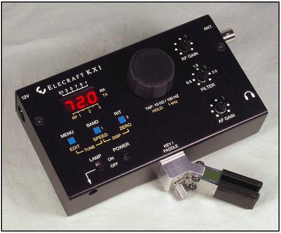
Perfect ergonomics for winter field operating
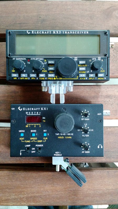
Elecraft KX2 (top) and KX1 (bottom)
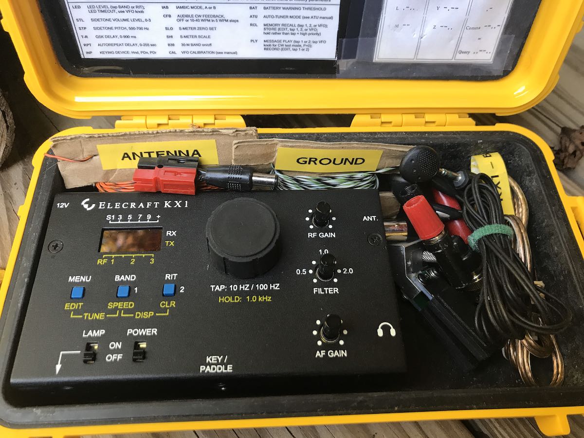
Even though the KX1 is a small radio, it was one of the first field rigs to have top-mounted controls. All of the buttons, knobs, and pots are well-spaced and easy to access. I especially love the pots used for the RF Gain, Filter, and AF Gain–raised, thin, tactile stems, essentially, that could be easily adjusted even while wearing thick winter gloves.
In fact, the KX1 is the only portable radio I’ve ever operated that didn’t require me, at some point, to remove my gloves.
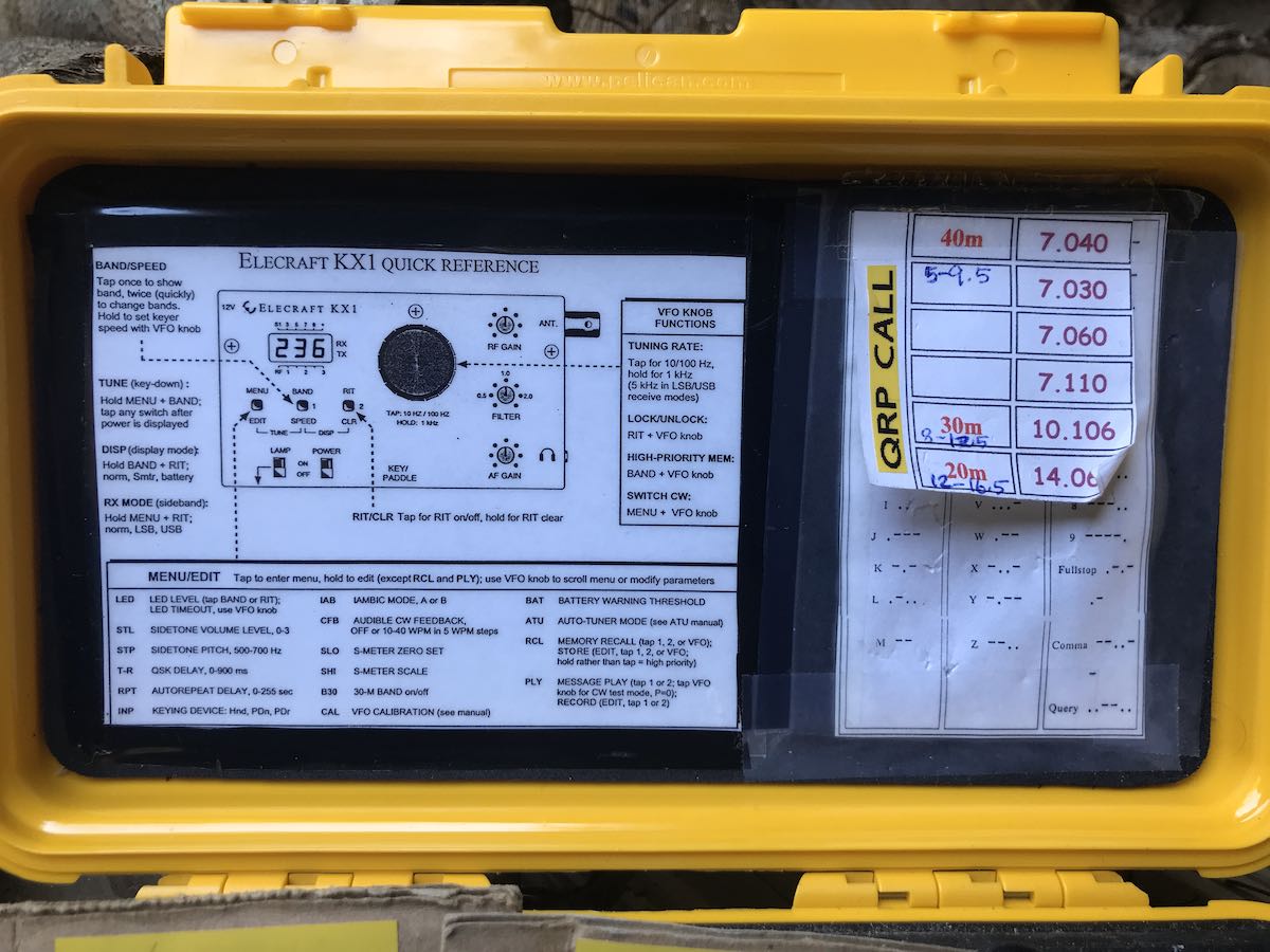
Insane amount of features
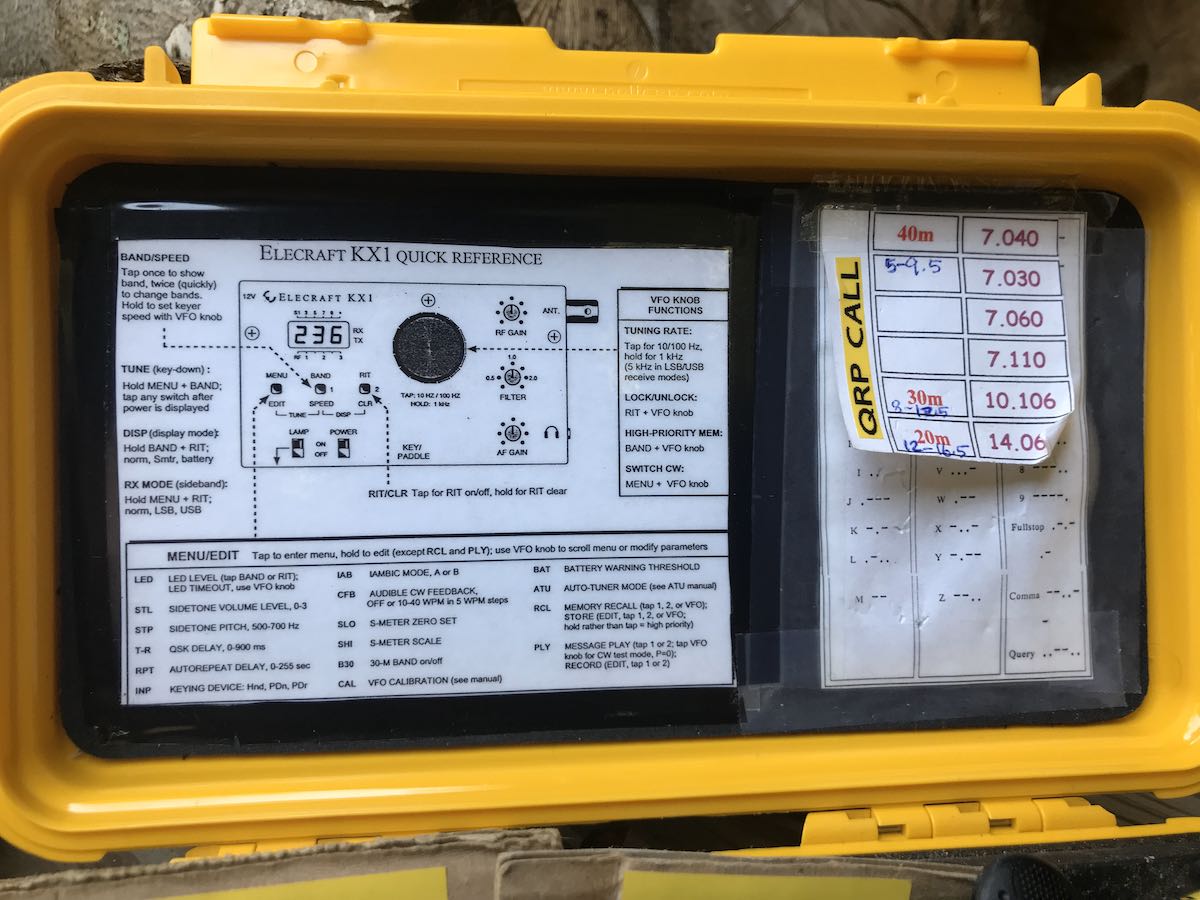
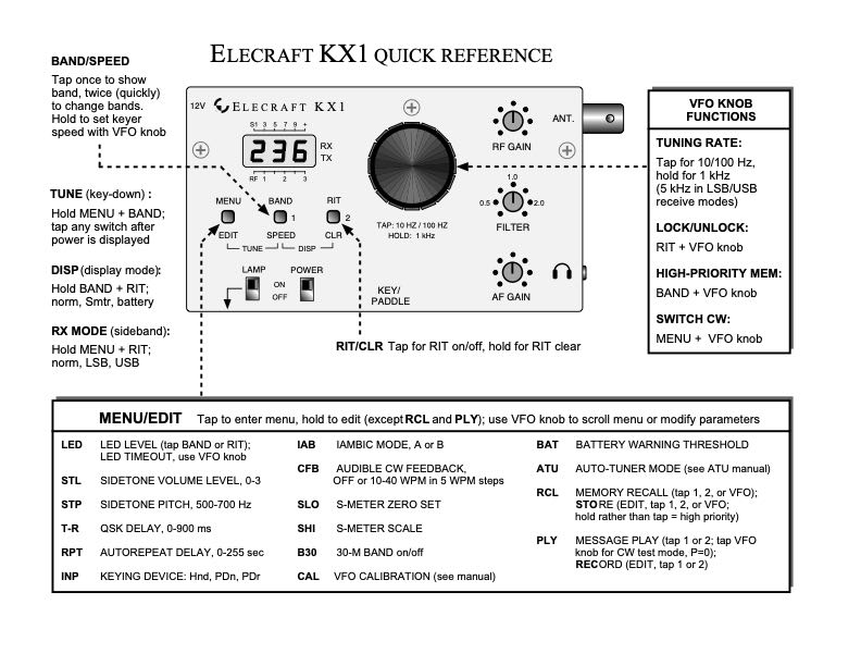 In true Elecraft fashion, the KX1 packs a ton of features specifically designed around field operation. Check out the features from their quick reference sheet above.
Here’s what happened
I published my article on QRPer.com and decided, on a whim, to see if there were any listings for the KX1 on QTH.com’s classifieds list via my QRP Transceiver shopping list.
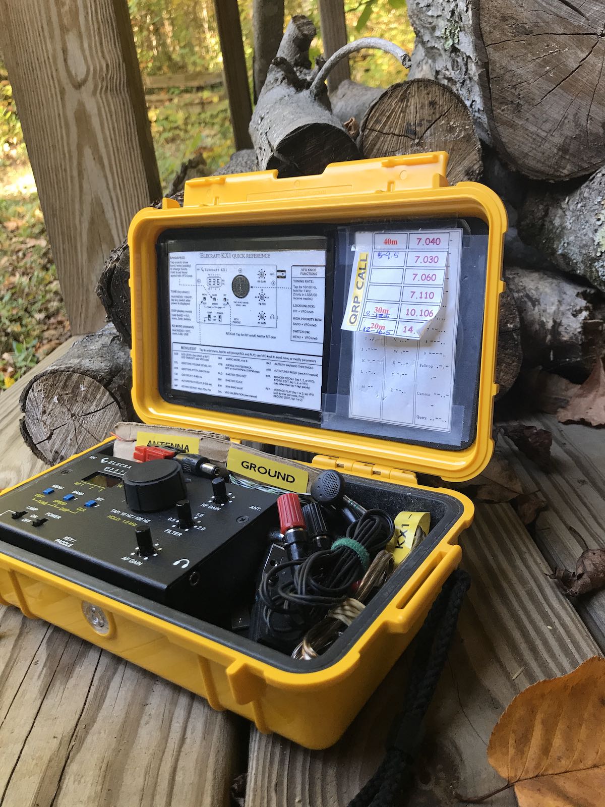
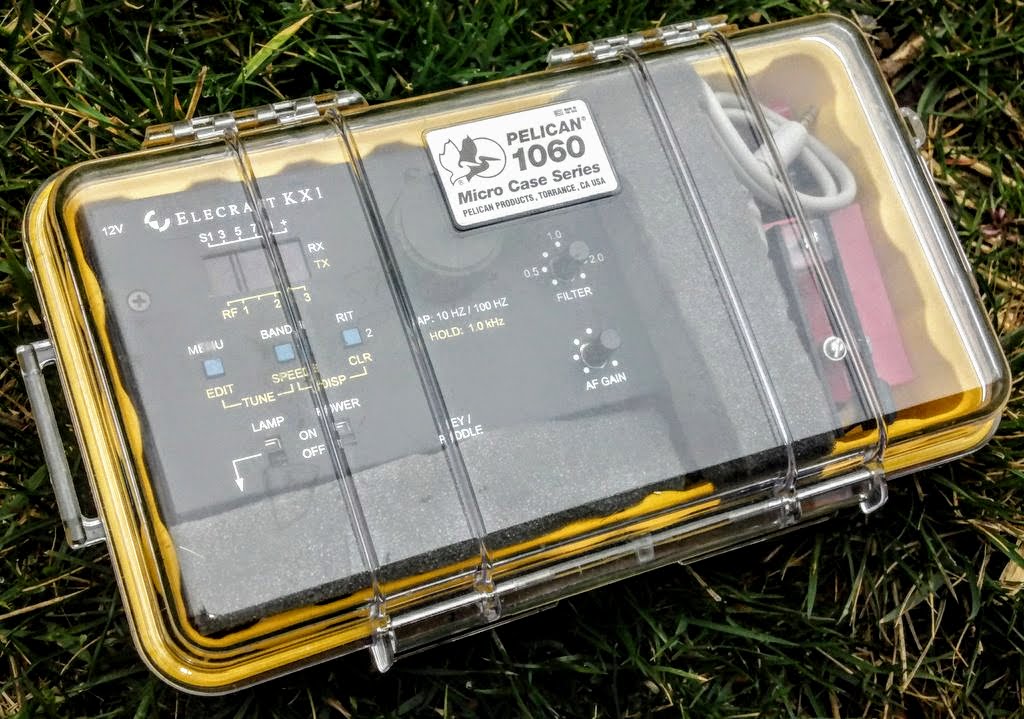
One ham had a KX1 listed. It was nearly identical to the one I owned and even included the same Pelican case. The only difference was my KX1 sported 4 bands (80, 40, 30, and 20m)–this one only had three bands (40, 30, and 20). Not a big deal because typically when I’m hiking I do little operating on 80 meters. If I decide to add 80 meters, I may still be able to snag the appropriate kit module.
The listing had no price.
I called the seller–who turned out to be fairly local–and within an hour he came back with his offer: $300 for the entire kit plus true shipping costs. I thought that was a fair price, so I purchased it and he even shipped it same day.
Moral of the story?
Next time I make a post about radios I’ve regretted selling, trading, or giving away, I need to publish it, then slowly back away from the computer.
I’m not going to be too hard on myself this time, though: I’m truly looking forward to putting the KX1 back in rotation here at SWLing Post HQ.
If you feel inclined, I would encourage you to comment on this post about radios you’ve regretted selling (click here to read the full QRPer post). I love hearing why specific radios have strong appeal for certain enthusiasts.
Just take my advice and stay away from the classifieds!

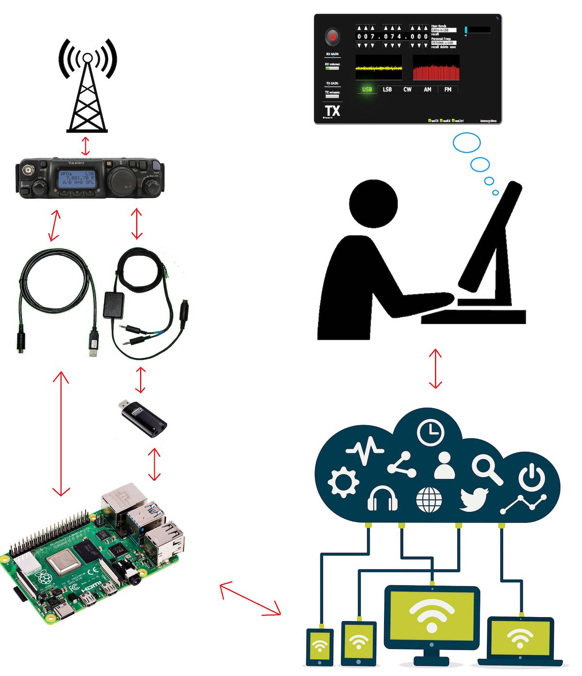
 Many thanks to SWLing Post contributor, Ferrie, who writes: