Droitwich Transmitter Site (Source: Wikimedia Commons)
Many thanks to SWLing Post contributor David Iurescia, who shares this BBC article about the end of an era in British broadcasting: the BBC has permanently switched off its longwave Radio 4 service after nearly a century on the air. The closure marks the end of longwave broadcasting in the UK, with the historic 198 kHz transmitters at Droitwich, Westerglen, and Burghead now falling silent after decades of service.
For many radio enthusiasts, this represents far more than the retirement of an aging transmission system—it is the closing chapter of one of broadcasting’s most iconic services, one that carried everything from the Shipping Forecast to Test Match Special and reached listeners across the British Isles and beyond.
Click here to read the article.
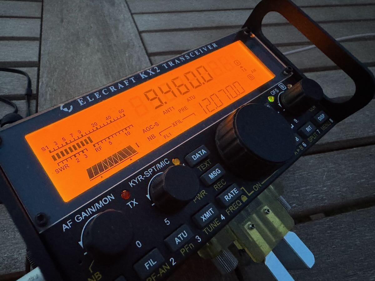
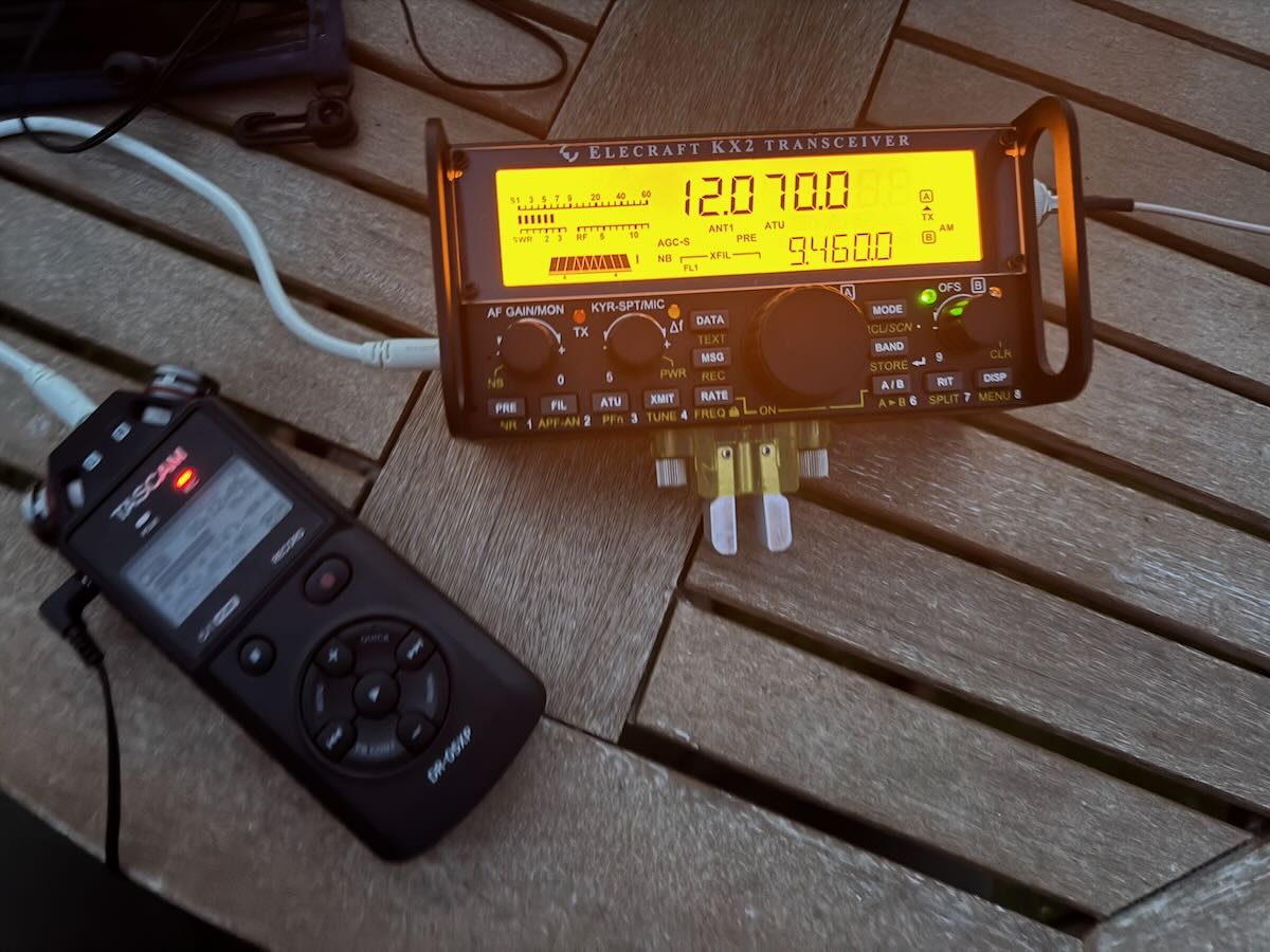
Many thanks as well to SWLing Post contributor Andy Wang, who shares this off-air recording capturing the final hours of the BBC’s longwave service before the transmitters went silent: