Category Archives: Radio Modifications

Repairing the Tecsun PL-600 after electrostatic discharge (ESD)

SWLing Post reader, Michael Taniwha (NZ1MT), has kindly documented how he repaired his Tecsun PL-600 after it went silent on the shortwave bands. If this has happens to you, don’t toss your PL-600, use Mike’s excellent guide below for an inexpensive repair.
(Click on images to enlarge)


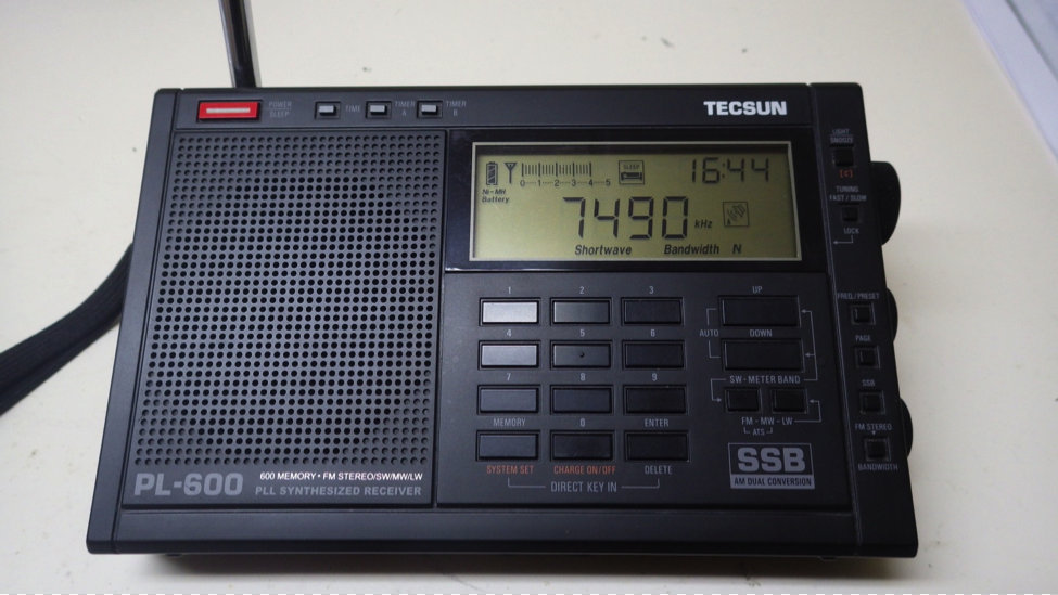
TECSUN PL-600 – Electrostatic Discharge Repair
Tecsun-PL600

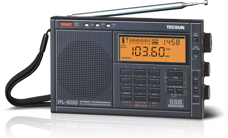
My TECSUN PL-600 had been a trusty bedside radio companion for the last two years. The radio is also my alarm clock and I use the timers to wake me up each morning to my local AM station WHYN or Radio Australia on SW.

On November 29, 2013 I turned the TECSUN PL-600 on and attempted to tune into some SW stations and was surprised to find the radio stone deaf on all the SW bands….similar to the Steely Dan song FM (No Static At All) except in this case it was SW (No Static At All). Immediately my first thought was that the radio had probably suffered an Electrostatic Discharge (ESD) when I had touched the external antenna while moving it around earlier in the day. I reset the radio and tested all the bands, AM and FM bands seemed to be working OK, yet SW remained dead.

My next step was to open up the radio and look for the obvious.

IMGP0092

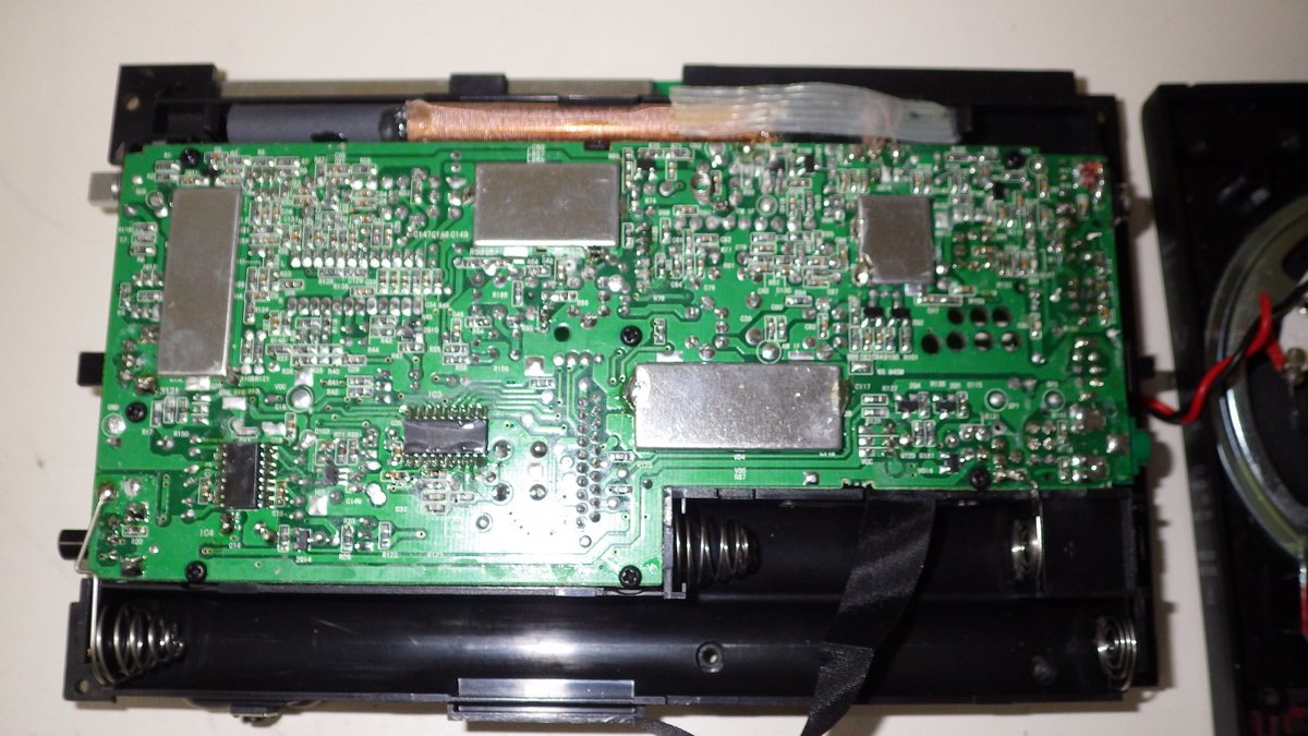
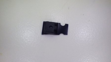
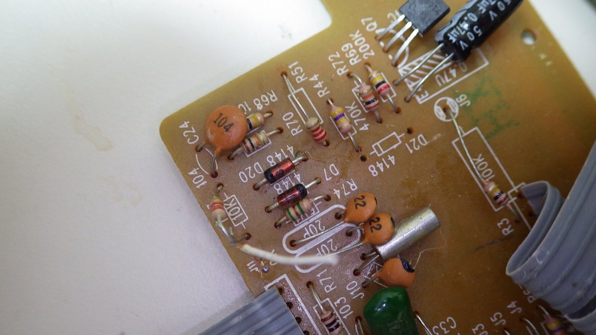
Upon opening the radio I was surprised to see two back-to-back IN4148 diodes (D17 & D18) fitted across the external antenna input to ground and that the diode D17 was cracked in half. The back-to-back diodes offer a very high resistance at the micro-volt RF level, but will conduct once the forward voltage (Vf) raises above 1.0V. So for the cost of a few pennies we have a relatively cheap and dirty ESD protection circuit.

IMGP0095

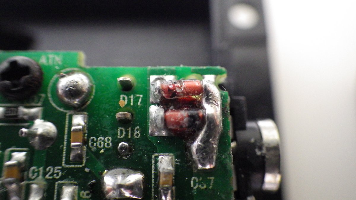
My first thought on the cause of the cracked diode was a manufacturing defect when the diode was soldered in at the factory (in fact I later discovered it was likely broken during assembly of the rear cover at the factory – read on). My next thought was just my luck that the broken diode was probably in the polarity direction that I needed the ESD protection.

The next step was to locate a schematic diagram and start circuit tracing to find the likely blown front-end RF pre-amplifier FET/MOSFET that had been damaged. As luck would have it a schematic of sorts is posted in the TECSUN PL-660/PL-600 Yahoo Groups. See the following Link.
http://groups.yahoo.com/neo/groups/TecsunPL660TecsunPL600/files/PL%20600%20Schematics/

The only issue is the text is mostly in Chinese! However, the parts on the radio PC board are clearly labeled as are the parts on the schematic.

IMGP0109 schem

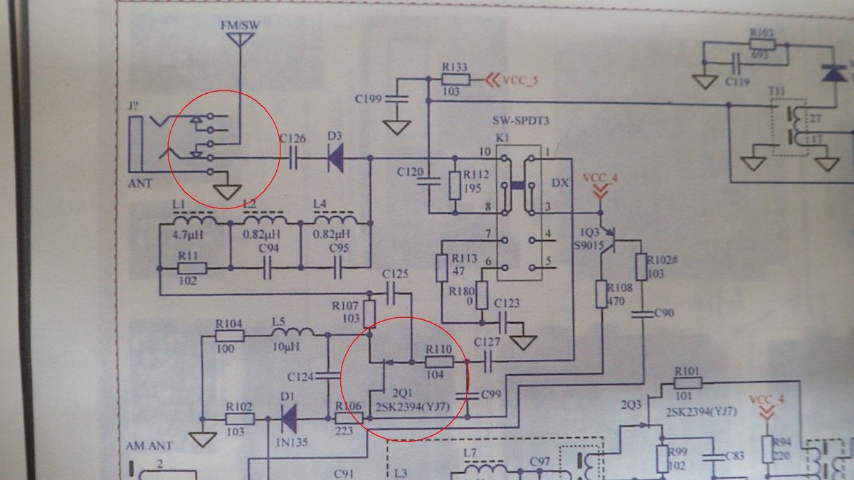
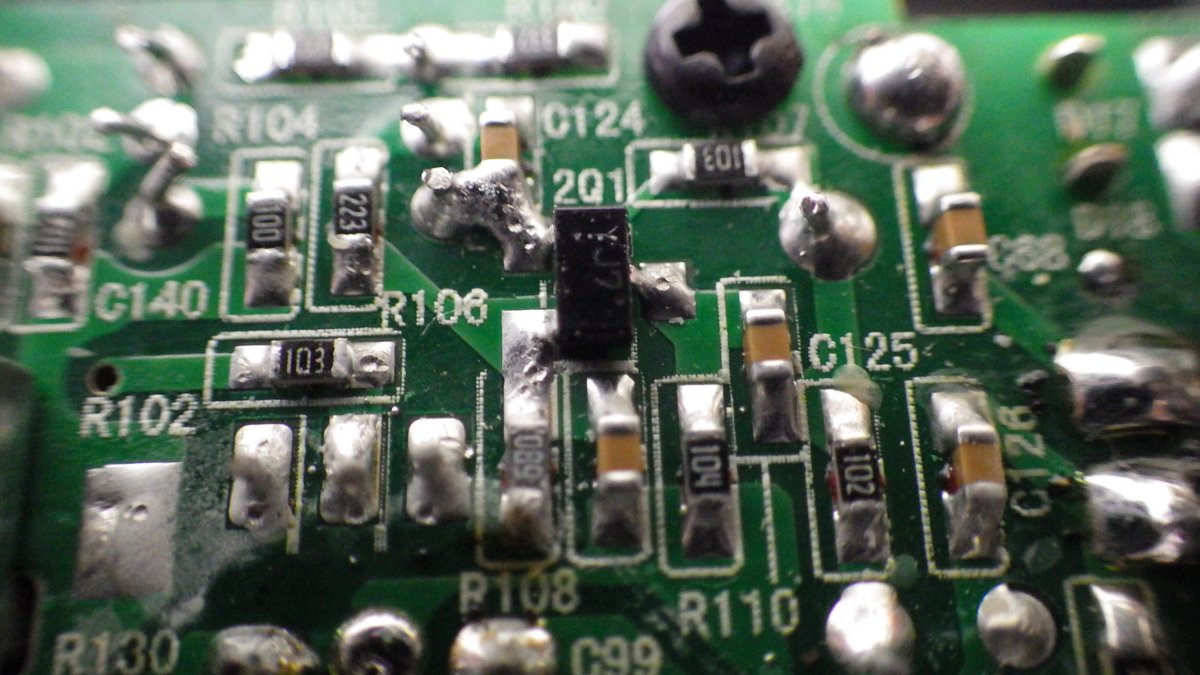
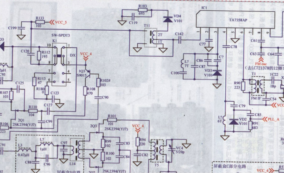
What I quickly notice is that the schematic shows no ESD protection on the front end (upper highlighted circle), but in fact the radio has additional parts D17and D18 (the back-to-back diodes), and C57 on the PC board coming from the external antenna jack. Whenever the external antenna jack is used the jack disconnects the radios telescopic antenna which is connected to C68 to the antenna jack switch circuit. After this antenna switch the schematic from C126 onwards is correct. Following the schematic we see that both the telescopic antenna and the external antenna go through the DX/NORM/LOCAL antenna switch to the IQ3 (AGC?) transistor and then to the RF pre-amp 2Q1 FET (lower highlighted circle). My educated guess was that the 2Q1 FET type 2SK2394 was damaged by the ESD. Yes the 2Q1 it is a very small SMD type FET.

IMGP0097

My reasoning for the 2Q1 having failed is that FM reception was not affected as the antenna circuit goes directly to the TA75358AP FM decoder chip IC1.

SchematicPL-600

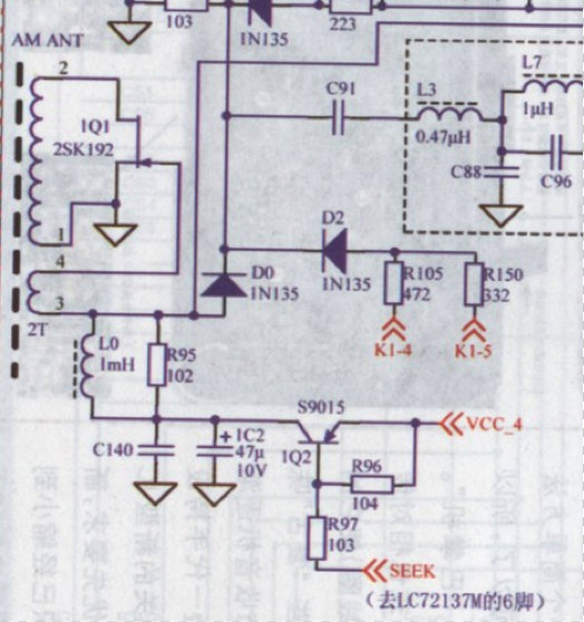
Similarly, AM reception was not affected as the AM signal is primarily from the ferret bar AM ANT coil that uses the 1Q1 FET for RF pre-amplification.

PL-600 Scem2

At this stage I contacted Kaito Electronics Inc. the official US based distributor of TECSUN radios and inquired if they provide component level repairs or provide replacement SMD components. The answer was no to both questions.

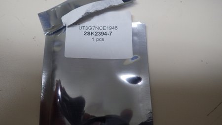
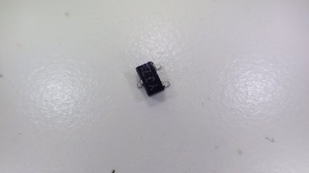
I then started hunting around online to locate a replacement 2SK2394 FET which is a Sanyo manufactured FET and finally found one for sale on eBay from hkutsource (Hong Kong UT Source) for $2 + $4 shipping. See following eBay link.

http://www.ebay.com/itm/2SK2394-7-Manu-SANYO-Encapsulation-SOT-23-High-Speed-High-Current-Switching-/130835554230?ssPageName=ADME:L:OU:US:1120

This FET is listed as a 2SK2394-7 but all the specifications line up against the specifications for a 2SK2394. I ordered it on December 6th and it arrived 10 days later enclosed in an ESD bag and packaged in a sturdy little box.

IMGP0116

IMGP0117

IMGP0118

Now the fun starts. To replace the 2Q1 SMD FET I used my needle nosed 40W soldering iron, vacuum pump solder remover and wore my ESD strap to stay grounded. First step was to remove the existing 2Q1 FET.

IMGP0119

Next step was to install the replacement 2Q1, if you haven’t worked with SMD devices before let’s just say it is like working with a live insect, they are small and seem to move around on their own accord.

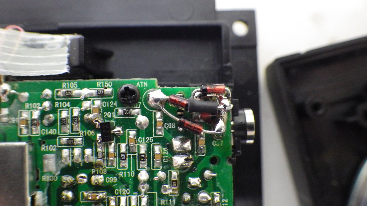
After much tooth pick (my hi-tech SMD tool) maneuvering I finally had it installed. OK I admit it is a little skewed. Have you noticed I have also installed a replacement D17 diode at the top right of the picture?

IMGP0122

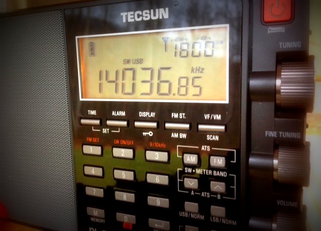
The moment of truth! At this stage I did a quick radio check and fired up the PL-600 on the SW band and tuned into CHU, the Canadian Time Station on 3330 kHz, and picked up a time pip signal. In addition I was tuning into other SW stations and had plenty of static as well.

I now decided to install additional ESD protection on the telescopic antenna input as well using two IN4148 back-to-back diodes. After a quick hunt around in my junk box I located an old PC board with a few IN4148 diodes attached. Quickly removed and tested them using my multimeter diode checker.

IMGP0112

IMGP0111

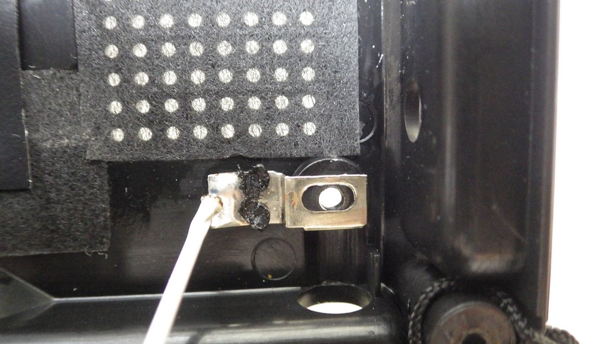
I then installed the additional ESD diodes as shown below (the ATN label on the PC board is where the antenna wire from the telescopic antenna on the back over is attached).

IMGP0124

Finally it was time to reassemble the radio. This is when I started having real problems as the rear cover just would not reattach. When I looked closely I could see that the plastic support screw hole on the rear cover for the telescopic antenna sits partially against the PC board where the D17 diode is located. Now that explains why that diode was cracked when I first opened up the radio at the beginning of this repair. It appears the two ESD diodes were probably a design afterthought and the rear case wasn’t adjusted to accommodate their location on the PC board.

IMGP0125

To get around this issue I removed the replacement D17 and relocated it to the lower part of the PC board below C57. Once I had moved D17 I could now reassemble the radio and again tested the radio. My TECSUN PL-600 is now back to its trusty role beside my bed and picking up SW stations.

Mike-Tecsun-PL-600-Repaired

In summary if you have a TECSUN PL-600 or PL-660 that is deaf on the SW band it is likely to be an ESD damaged 2Q1 RF pre-amplifier 2SK2394 FET. For $6 and some time and effort you can replace the FET and have your radio back up and running like new.

Michael Taniwha – NZ1MT
Email: To send Michael an email, simply insert his callsign @YMAIL.COM
December 17, 2013


Many thanks, Mike, for the excellent documentation and detailed photos! 

Note that you can also download Mike’s guide as a PDF on the Tecsun PL-660/600 Yahoo Group (membership required).

Tecsun PL-880: How to fix the audio level problem

photo (5)As more and more people are beginning to receive their Tecsun PL-880s, I’m receiving emails and noticing comments regarding an “audio level problem.”

Here’s the symptom: when you tune your brand new PL-880 to a relatively weak station on AM or shortwave, the audio level jumps from low to high in what seems like a random pattern.  It’s very annoying. Like me, many assume they have received a faulty unit–some have even sent their new PL-880 back for refund.

In reality, the PL-880 is simply following a default muting threshold level and the audio is responding accordingly. Fortunately, there’s an easy fix for this–you won’t find it in your owner’s manual, but you will find it in one of the first PL-880 posts I published:

Hidden feature: Adjusting the Tecsun PL-880 muting threshold

I hope Tecsun will start shipping their PL-880s with the threshold set to “00” or off.  It would certainly lead to less confusion and frustration.

You can follow all Tecsun PL-880 updates by bookmarking/checking this link.

Jeff designs an SDR “Go Kit” around the Softrock Ensemble

SoftrockGoKit1Jeffrey Fritz (WB1AAL) contacted me with details about his SDR (Software Defined Radio) “Go Kit” and has kindly allowed me to post it.

Jeff writes:

As a reader of the SWLing blog, I know that you are very interested in SDR. And you probably know that a “Go Kit” is a portable ham radio system in a case that can be moved at a moment’s notice and set up at another moment’s notice virtually anywhere.

I have a VHF Go Kit made up for emergency events. It is complete with waterproof carrying case, Aden PCS-7000H two-meter transceiver, a Kenwood VHF tuner, a Kenwood SW-100 VHF SWR bridge and two antennas (a 2-meter J-pole made out of twin lead and a two meter mag mount.) But what if there is a need to monitor the HF bands during the same event?

Now that I own a Flex-1500 SDR transceiver, the Softrock Ensemble SDR receiver that I bought a while ago has become somewhat redundant. It is still a serviceable radio and works fine, but it can’t hold a candle to the amazing Flex-1500. While I could turn it into a panadapter or sell it on eBay, eHam, etc., I had a better idea.

To monitor the HF ham bands, I could use something like my Grundig G3 shortwave radio in my Go Kit. While it is portable, battery operated and will tune LSB and USB, listening to SSB or even CW in an emergency situation with the G3 can be a bit of a chore. (Think of the old boat anchors with their main tuning and fine tuning band spread dials, but now make both dials tiny and you’ll get the idea.) Instead, why not build a 12-volt battery supply with common, easy to obtain batteries? I could connect it to the Softrock Ensemble and then via a USB audio interface to a battery powered laptop. Add a pair of headphones and we are in business.

That is just what I’ve done.

I’ve attached some photos of my most recent project–done this past weekend actually. [Check out photos above and below] It’s an SDR Go Kit. One of the attached photos shows the laptop and the Softrock Ensemble SDR receiving 40-meter band SSB while entirely being operated on battery power. There is no power switch. You simply pull the DC jack out of the Softrock Ensemble SDR radio when it isn’t in use. Simple as it gets! The other photo shows the battery pack built into a (ahem!) Preparation H Pad holder pack. (Now, I am not saying who used this!)

Ah but what will battery life be like with 8 C cells in series driving the receiver? It’s too soon to say because I just put it together an hour ago. But here’s a guess:

SoftrockGoKit2The Softrock Ensemble draws 18 mA at 12.6 volts (my measurement.) An Alkaline ‘C’ battery can supply up to 8,000 mAh, so doing some math and assuming fresh batteries, the battery pack should run the radio for roughly 400 hours. (Hopefully my math is correct!) If so, then I think that the laptop batteries will give out long before the life span of the C Cell is reached!

73,

Jeff, WB1AAL

Jeff, this is an excellent use for the Softrock Ensemble. I imagine it will run for a very long time drawing only 18 mA. I have a “Go Kit” for QRP ham radio purposes and one for SWLing during travels. You’ve inspired me to piece together a proper receiver “Go Kit” to be used in case of emergencies.

Readers: If you have a project, like Jeff, that you’d like to share on the SWLing Post, feel free to contact me with details!

Using the RTL2832U $20 SDR for HF & trunk-tracker scanning?

DE_DVB_T_1In response to our post on inexpensive SDRs based on the RTL2832U, Jeff Benedict writes:

Here’s a website that has a lot of info on cheap SDR gear.  They have a write-up on an external board which adds HF capabilities.  I have one but haven’t done anything with it yet.

http://www.hamradioscience.com

Jeff  KB7AIL  CN88

Thanks, Jeff! Has anyone tried HF with any success? I’m curious how well this über-cheap receiver will cope with adjacent signals and blowtorch stations within the HF spectrum.

Meanwhile Neil, blogger on Fofio, commented:

I have an RTL-SDR system up and running.  I have done 2 demonstrations for my local Ham Radio club.  One on the basic setup and use of the dongle, using both SDR# and HDSDR.  The other presentation showed the remote receiver capability using a Raspberry Pi as the receiver with the dongle attached and a remote SDR# computer decoding the stream over a network connection.  Once I compensate for some minor frequency discrepancies it’s a pretty good receiver.  The only issue I have noticed with mine (one of the early E4000-based models) is a tendency to overload in the presence of a strong signal.  We have a pretty powerful 2 Meter repeater less than a 1/4 mile from our home, and when it’s active it causes some strange results with the RTL-SDR setup.

I have yet to try one of the HF converters they make for these.  I hope to do that soon.

Another project I was reading about today that I may try out is using 2 of the dongles at once to create a trunk-tracker scanner.

Wow! Two $20 USB SDRs and a little PC magic could yield a trunking scanner? I want to hear more about this. Trunking scanners tend to be both expensive and complicated. If a web-updated database could be downloaded and used to control this sort of rig, the possibilities would be most impressive!

Neil, keep us informed!

Bill helps with low-power, license-free broadcasting

HobbyBroadcasterIn reference to our post, Dave’s FM Station Empire, SWLing Post reader Bill writes:

Nice article on the use of low power broadcasting. For the last 5 years my site, HobbyBroadcaster.net, has been helping radio enthusiasts along with schools and businesses learn how to use legal, low power, license-free Part 15 radio for a variety of uses. I created the site due to my involvement with starting a campus-limited high school station and discovering the lack of quality resources available for school-based broadcasters unable to obtain an FCC allocation. With many hobbyists also using this same technology on AM to serve their neighbors with micro radio it only seemed natural to expand the interest to hobbyists, too.

Also, Part 15 regulations allow for some use of the shortwave bands for experimental broadcasting with the most common frequency used by hobbyists being 13.56 MHz.

A simple upgrade for your Ten-Tec Model 1254 shortwave receiver

In the video below, Alan (W2AEW), shows us the installation and basic operation of an upgraded micro-controller for the Ten Tec Model 1254 Superhet Receiver Kit.

As Alan points out in the video, this is one of two upgrades offered at Cholakian.com. Both upgrades enhance the operation and usability of the Model 1254, giving it many more choices of tuning steps (yes!), the ability to automatically turn off the LED display, more memories and allowing you to eliminate the 9V battery back-up. This basic upgrade costs $38, the premium upgrade costs $68 even allows you to control the receiver via your PC.

Thanks, Alan, for showing us just how simple this upgrade is to perform:

You can see more of Alan’s projects at his website.