 Many thanks to SWLing Post contributor, Ron, who shares his thoughts on comparing two portable longwave antennas:
To begin, for reference, check out this post where The Professor reviews the RFA200. Also, check out the following video from the replies of that post:
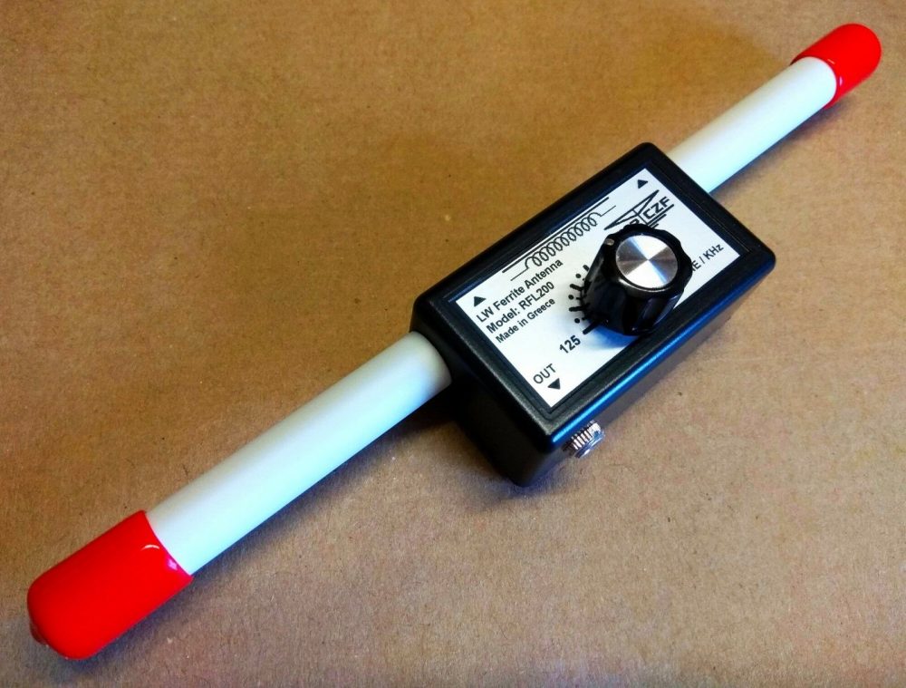
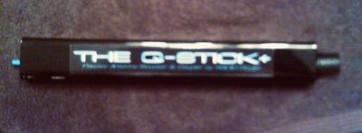
Both the RFL-200 and the Q-Stick came in today.
Performance of both was very nearly identical but for now the Q-Stick wins on price ($67.50 vs. $75.78 delivered) and the Q-Stick does both LW and MW.
But Gerry says he’s going to close RadioPlus early next year so-presumably-
that will leave just the RFL-200 and its REA-200 sibling.The “200” no doubt comes from the length, 200mm or 8 inches…the Q-stick
uses a 7-3/4 inch ferrite bar which is probably why the similar performance.There is one thing: the small tuning knob is not hard to turn on the RFL-200
as it was on the REA-200 tested earlier but a bigger knob would be nice.But the tuning cap uses a 1/8th inch shaft so finding a larger knob is too
much bother, most are for 1/4 inch shafts.By comparison the Q-Stick has a nice big knob and is quite easy to tune.
So for now the Q-Stick would be the better buy, but don’t tarry.
[One more note,] if you want the most bang for your buck, forget both of these, get
a PK Loop for $90.60 delivered (be sure to specify the 155-500 kHz model).
Thanks for sharing your thoughts, Ron!
Click here to check out the RFL200 longwave antenna on eBay.
(Click here to view the RFA200 mediumwave version.)
Click here to check out the Q-Stick antenna at Radio Plus.
Do you enjoy the SWLing Post?
Please consider supporting us via Patreon or our Coffee Fund!
Your support makes articles like this one possible. Thank you!