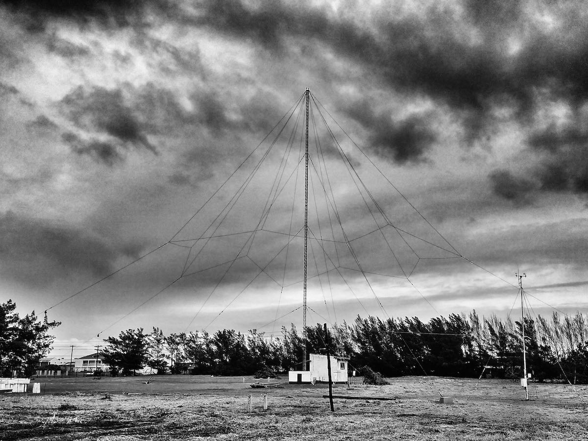
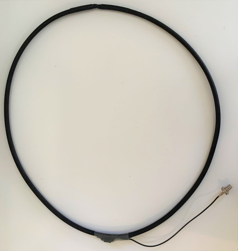
Category Archives: Antennas

Grayhat’s NCPL (Noise-Cancelling Passive Loop) antenna “tweak”

My NCPL antenna

Many thanks to SWLing Post contributor, Grayhat, who shares the following modification he made to a Noise-Cancelling Passive Loop antenna last year. He’s kindly allowed me to share his notes here, but apologized that at the time, he didn’t take photos of the project along the way and recycled many of the components into yet another antenna experiment.

Grayhat writes:

Here’s a simple tweak to the NCPL, made easy for anyone. Let’s start with the commercial NooElec 9:1 balun version 1 (not 2) … made in USA.

Look at the schematic of the balun:

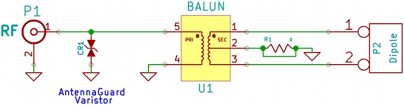
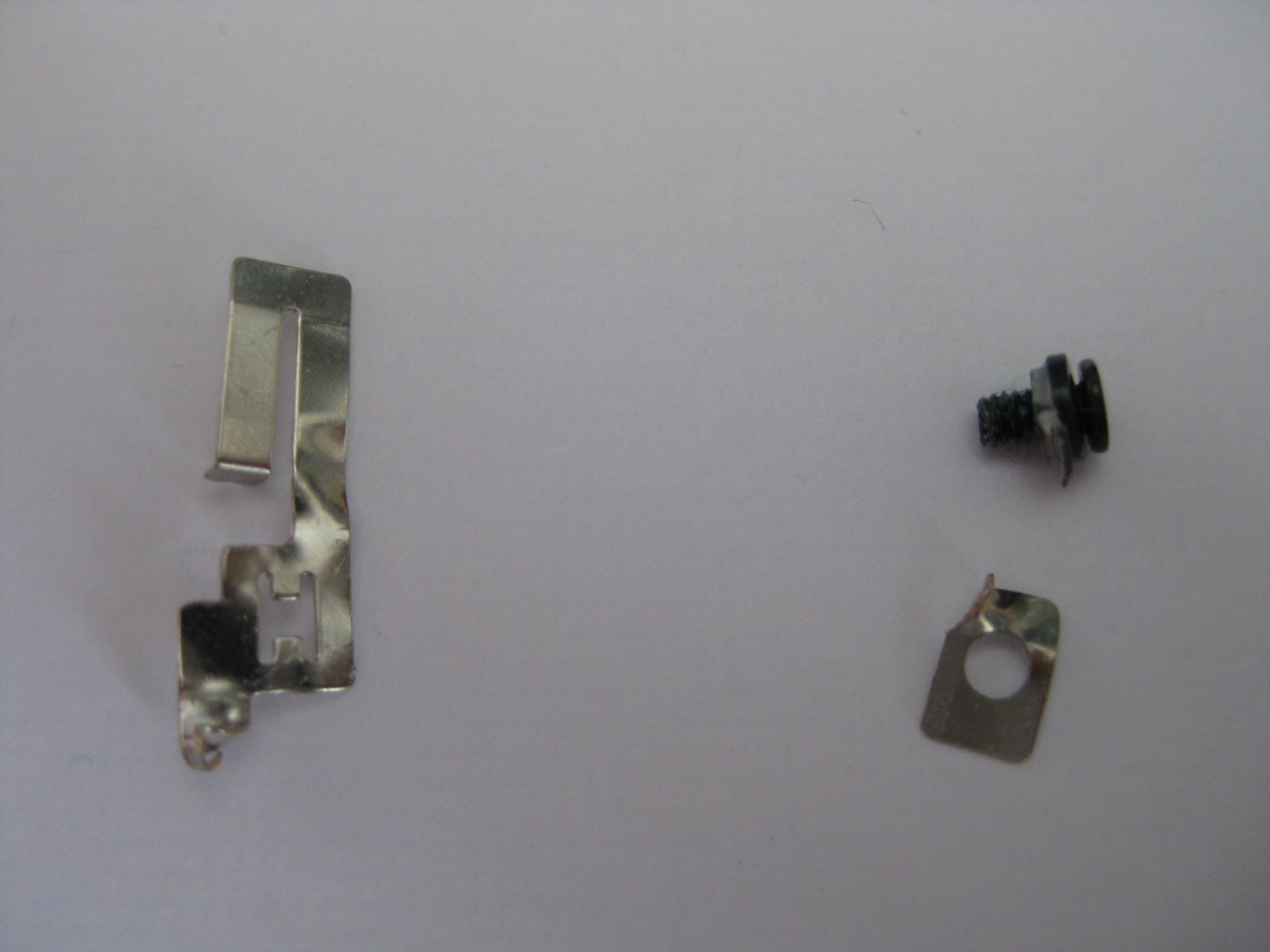
Cut the R1 (0 Ohm resistor – jumper) so that the center tap of the transformer won’t be connected to ground, then solder a short piece of wire to the tap.

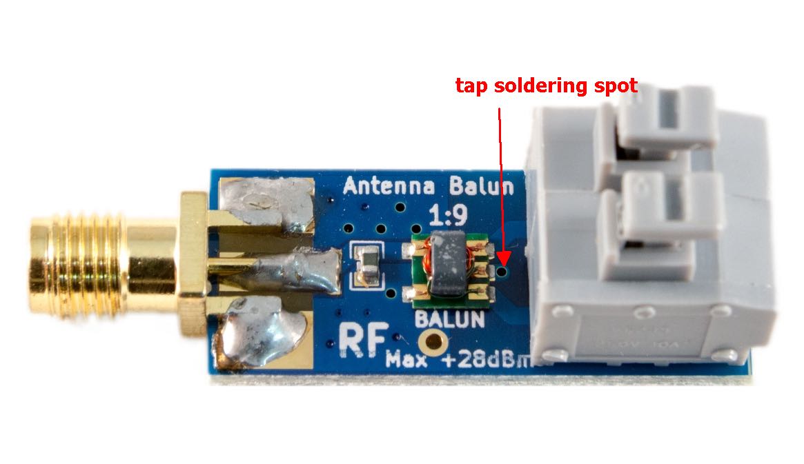
The first pic (top) shows the balun seen from top side, the arrow indicates the small hole going to the transformer tap.

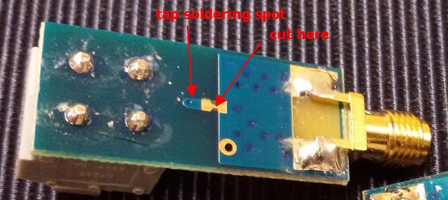
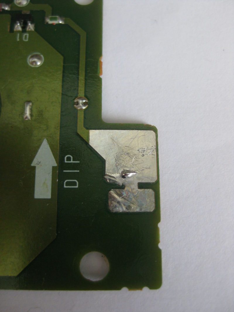
This pic shows the bottom of the board with the trace to cut and the spot for soldering the tap wire (needs cleaning with a bit of sandpaper to remove the cover paint). The solder is as easy as 1-2-3 once the trace is cut and the spot cleaned just insert a wire from the top of the board and solder it to the bottom and there you go!

Build the NCPL using “fat” coax (RG8 will do) with the top cross connection.

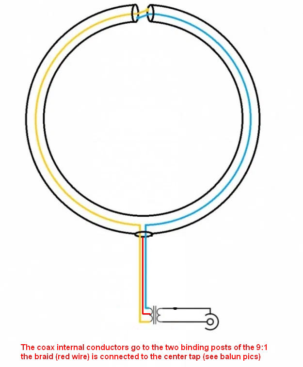
NCPL modification schematic

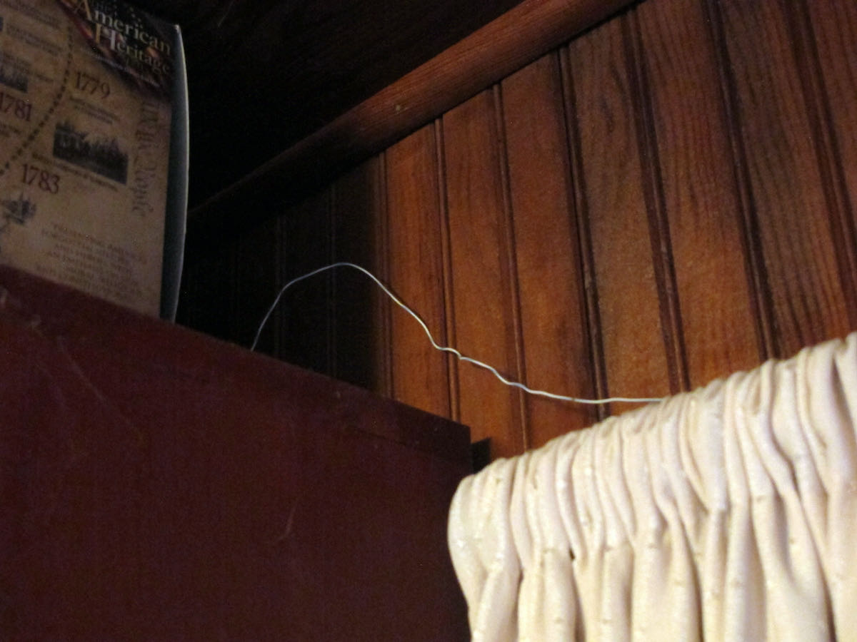
Side note: the top “cross connection” is the weak point, so it would be a good idea putting a short piece of (say) PVC pipe over that point, the piece will also help suspending the loop or sticking its top to the support pole, as for the feedpoint, a small electrical junction box will fit and protect the tiny balun from bad weather

Now the difference: connect the two center conductors of the NCPL to the balun input and the braid to the wire going to the center tap (as above).

Such a configuration will give some advantages over the “standard” NCPL one. The loop will now be galvanically isolated from the feedline/receiver so it will have much less “static noise.” Due to the tap, the typical 8 pattern of the loop will be preserved, this means that the loop will now have much deeper nulls.

By the way, the balun could just be wound w/o buying it. I suggested the nooelec since that way anyone with little soldering ability will be able to put it together. Oh and by the way it’s then possible adding a small preamp at the balun output if one really wants, any preamp accepting a coax input will work. 🙂

Again, if you can/want, give it a try !

Many thanks for sharing this, Grayhat! We always welcome your inexpensive, innovative urban antenna projects!

Post readers: If you have question, feel free to comment and I’m sure Grayhat can help. 

Recommendations for an HF/VHF/UHF station in an apartment or flat

Photo by jay blacks on UnsplashMany thanks to SWLing Post contributor, Jamie, who writes:

Hi,

I would like to ask a few questions about what would be a good set up for my situation.

I am in a 2 storey property, which is not owned by me (renting via community/public housing), located in a large city in Australia. I currently have an SDRPlay RSP2, along with standalone AM/FM tuners – Sony XDR-F1HD and Onkyo T4970. The computer and all radios are upstairs at the back in a room that is not attached.

Given renting would limit what I can do, what would be best for me to get. For MW and SW frequencies, I am trying to decide between the MLA30+ or the AOR LA400. For above 30MHz (6m, 2m, broadcast FM etc) I am deciding between the AOR SA7000 or a Discone.

I have been told that putting antennas in the roof space is not recommended. Would they work fine in the room near a window? I should mention, I do have a 50ft end fed longwire with 9:1 balun, that has been in storage and never used.

I am also looking at upgrading my receiver. Trying to choose between the WinRadio WR-G305e or the Icom IC-R8600 (would also get the RS-R8600 CD software for computer controlling the receiver). How do the specs compare between these two?

Thanks for your time, and hope that wasn’t too many questions.

Regards,

Jamie

Thank you for your inquiry, Jamie, and I hope you don’t mind, but I’m sharing this message as a post as we have readers who are in the same type of living situation and listening environment. In addition, I believe owners of the gear you’ve mentioned might be able to offer some helpful advice!

I can tell you that you’re correct: in general, antennas want to be near windows or, better yet, outdoors. Even placing an antenna on a balcony can make a big difference in terms of lowering the noise floor. This is less an issue with VHF/UHF, but those antennas also benefit from being outside since there’ll be less attenuation from obstructions.

For HF, I would personally suggest you check out the MLA-30 loop first since it’s such a modest investment and is fairly flexible in terms of how you can configure it. I’m sure our regular contributor, Grayhat, will have some helpful advice as he’s a bit of an expert with urban HF antennas.

Also, the IC-R8600 is a brilliant wideband receiver. Depending on what you wish to have for frequency coverage, I would also suggest you check out the Icom IC-705 transceiver (noting that its RX coverage is not as comprehensive as that of the IC-R-8600).

Post readers: Please feel free to comment with some suggestions for Jamie, especially if you have experience with urban radio listening.

Mike Harwood explores active magnetic loop antennas with SDRplay

Many thanks to Jon Hudson with SDRplay who shares the following announcement:


Introducing a new series of videos comparing the performance of wideband active loop amplifier/antennas for HF frequencies and below. In this introductory video, Mike Harwood shows how an RSPduo enables a real-time comparison of two antennas – in this demo, he uses a Wellbrook 1530AN and one of his own compact loop creations. You can see that he has lined up several other active loop antennas/amplifiers to try in future videos, including the Bonito Megaloop FX, the LZ1AQ amp and the Cross Country Wireless amp.

SDPlay will endorse antennas which work well and formally recommend them on its website antenna suggestions page: https://www.sdrplay.com/antennasuggestions/

This is one of many videos from SDRplay – makers of the RSP family of SDR radios. See the full list of SDRplay videos and applications documents on: https://www.sdrplay.com/apps-catalogue/

The RSP family of SDRs from SDRplay cover 1kHz to 2 GHz with no gaps and give up to 10MHz spectrum visibility.

SDRplay is a UK company. The RSP SDR receivers are made in the UK and can be purchased for worldwide delivery directly from http://www.sdrplay.com/ (click on purchase and select your country to view shipping costs) or you can buy from any of our worldwide resellers listed here: http://www.sdrplay.com/distributors/ Many of the resellers offer local free shipping and/or local language technical support.

The SDRplay YouTube Channel is: https://www.youtube.com/c/SDRplayRSP

The Beam Box Model FM 10

Many thanks to SWLing Post contributor, Paul, who recently shared a link to this Craigslist listing and asked if anyone in the SWLing Post community might be familiar with this Beam Box Electronically Directable FM Antenna.

He included a link to the following review in an archived issue of Radio-Electronics:
https://worldradiohistory.com/Archive-Radio-Electronics/70s/1978/Radio-Electronics-1978-03.pdf

The Cragslist post actually included the following images of the owner’s manual:


I’ll admit that I’m not at all familiar with this antenna, but I see how it might have been ideal for a component system. I’m curious if it was FM DX-worthy!

Please comment if you’ve ever owned the Beam Box!

Frank seeks guidance to repair his Sony AN-100E antenna

Many thanks to SWLing Post contributor, Frank Sturzaker, who writes:

I am a new SW listener in the UK and am using an elderly Sony ICF SW100E picked up from selling website here in the UK fairly cheaply as a starter. It gets excellent reviews and seems to do what is required very well. A couple of weeks ago I also picked up a non-working Sony AN-100A external antenna at a charity / thrift store here in the UK. Cheap because not working.

The antenna section simply pulled out of the plastic case so I opened it up to have a poke about inside to try to solve the problem.

The antenna has been “ripped” from however it was mounted and has taken the thin metallic shaped piece / strip that somehow connects it to the circuit board and twisted it. I would guess that this has happened when trying to rotate the extended antenna when the extending sections had become too stiff to rotate – the pieces visible from outside the unit would not rotate inside the fixed section that sits in the unit.

Photos

1 – This is what I bought (although the antenna itself was in the correct place in the case):

2 – This is a close up of the base of the antenna when first bought:

3 – The two halves of the case with the antenna in place but about 0.5″ short of where it should be:

4 – A close up of the ‘loose pieces’ from inside the case and the bottom of the antenna – on the right are the pieces that were left on the antenna and on the left is the this metal piece that makes contact with the circuit board from the antenna

5 – Photo of antenna screw hole in rear of case from inside – the broken plastic is obvious round the screw hole:

6 – Photo of underside of circuit board showing the flat metallic area where the metallic strip from the antenna makes contact:

My questions about how it all fits together (as a starter) are:

    • Is it ONLY the screw from the outside holds the whole antenna assembly in place or is it fixed with glue etc. when originally shipped? It looks to have been ONLY the screw because there are no traces of any adhesive etc.
    • Should the antenna be able to rotate at its lowest section – like on the SW100E?
    • Is the thin metal strip fixed to the circuit board by anything (solder??) or does it just ‘brush against’ the metallic surface?
    • If I simply fix the antenna in place with epoxy or similar and run a connector between the bottom of the antenna and the circuit board will this work or are there other things that should be done or done in a specific way?

If someone can help then great. I repeat, I am not an electronics wizard – a master with a soldering wand I am not!!!

I could go at this like a bull at a gate but advice would be appreciated if there is any out there.

Post readers: if you can offer Frank some advice, please comment. Also, if you own an AN-100E and could share some internal photos, that might help him sort out how it was originally attached inside.

Jock designs a Horizontal Room Loop to cope with reception issues

Many thanks to SWLing Post contributor, Jock Elliott, who shares the following guest post:


There’s a 50-foot antenna in this room. Can you spot it?

Got reception issues? An idea worth considering: the “Horizontal Room Loop.”

by Jock Elliott (KB2GOM)

When my radio room was in the front of the house (on the east side), it was easy to run a feedline to a large RF-hungry SWL dipole with various stubs and feeders.

Now, however, with my “shack” moved to the SW corner of the house, any attempt to mount an outdoor antenna of any significant length raised potential safety issues because of nearby electrical lines.

Monitoring VHF/UHF is no big deal because of high-performance scanner antennas. HF, however, presents challenges.

My main SWL receiver is a Satellit 800, which has the guts of a Drake R8 and also has a large telescoping vertical antenna. It works okay, but I wanted more signal. I had been looking at small loops and got some great recommendations on Radio Reference, but then I had a thought: what if I turned the 8′ x 12′ room into a giant horizontal passive loop?

Here’s a hint.

So I called a ham friend and ran the idea by him. “Sure,” he said, “give it a try.” He gave me 25 feet of 4-conductor phone wire. Before I could use it, I had to strip off the outer insulation so I could get at the four separate insulated wires inside. The better half helped. Once I had the four wires, I connected two of them together and ran the resultant 50-foot strand around the perimeter of the room by taping the wire to the top of window frames and hiding the wire on the top shelves of book cases. As a result, the horizontal room loop is near the ceiling, about 7 feet in the air, and the room itself is on the first floor.

With the loop in place, I hooked the ends to the clip-in terminals on the back of the Satellit 800.

There’s a switch on the back of the 800 that allows me to quickly compare the loop with the radio’s built-in vertical antenna. And . . . it works! It pulls in more signal than the vertical (as measured on the signal strength meter), but I have not noticed a dramatic reduction in noise. On some stations, the horizontal room loop brings the signal up to full scale, and then the sound is very agreeable indeed.

In all, I am pleased with the results.

For anyone who wants squeeze more performance out of their shortwave receiver, I can recommend giving the horizontal room loop a try. It’s not expensive; it’s relatively easy to do (and undo if you don’t like the results), and just might improve your shortwave reception.

If you are not blessed with a bunch of window frames on which you could tape the wire for your room loop, you’ll have to get creative, but with lightweight wire, you don’t need a massive support structure. Tape, map tacks, or even self-adhesive Velcro segments might work for putting your room loop in place.

I don’t claim that this is the “ultimate” SWL DX antenna, but it certainly improved my situation. Perhaps others have suggestions for improving it.

— Jock Elliott, KB2GOM