Many thanks to SWLing Post contributor, Joachim von Geisau (DH4JG), for the following guest post:
Signal distribution at SWL camps: The new JK-1000 HF distributor
by Joachim von Geisau (DH4JG)
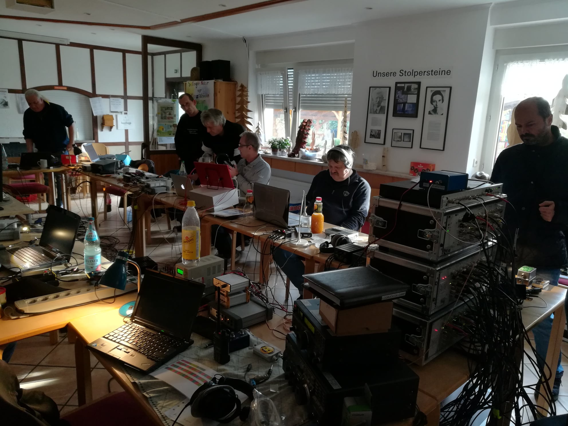
The Friends of Radio NRW – an independent group of shortwave listeners and radio amateurs in Germany – have been organizing 2-3 SWL camps per year for a number of years, where they meet as far away as possible from electrical noise in order to listen to shortwave together.
To distribute antenna signals, we have previously used an RFT AVV01 antenna distributor.
At an SWL camp there are high demands on signal distribution. Both very weak and strong signals should be distributed well, un-distorted, without noise and other interference. The signal levels are approximately between 0.2 ?V (S1) to over 5 mV (S9 + 40 dB), with a frequency range of at least from 150 kHz to 30 MHz, thus broadcast bands from LW to SW are covered, also all amateur radio bands from 160 m to 10 m.
Popular among listeners are RFT AVV01 RF distributors from the former GDR, at least 30 years old. However, the use of an AVV01 has several disadvantages: high power consumption, difficulties in getting spare parts, high upkeep with corroded contacts and the like. In addition, the transmission of the LW/MW range drops, which is a disadvantage especially for MW listeners. The NV-14 system from Rohde & Schwarz from the late 1960s has the same weaknesses.
Two years ago, the desire arose to develop a concept for the replacement of the RFT system.
The following aspects were important:
- Frequency range at least 100 kHz – 30 MHz, as linear as possible
- frequencies below or above desirable
- Running on 12 V DC or integrated noise-free power supply
- Remote power supply for active antennas
- Robust structure
- Versatility
- Hobby friendly budget
The amateur radio market offers several products for RF signal distribution (e.g., ELAD, Bonito et al.), but no solution to distribute 6-8 antennas to 10-12 receivers. It was clear from the beginning that DIY development was inevitable.
The starting point of the considerations was to integrate remote power supply for active antennas, an amplifier stage and a distribution network.
Such a distributor is able to distribute an antenna signal to several receivers; several antennas require several such distributors, which led to the decision to implement the project in plug-in technology.
With OM Frank Wornast DD3ZE (www.dd3ze.de), known e.g. for his converters, filters and the like, a well-known RF developer could be won, who took over the implementation of the concept based on the detailed specifications. OM Wornast first produced a prototype without remote power supply, which already did an excellent job of RF signal distribution.
A “hardness test” at an SWL camp showed that this distribution module easily fulfilled our requirements: Frequency range 10 kHz – 50 MHz (also usable with a few dB loss above 50 MHz). Supplemented by a switchable remote power supply and a 90V gas discharger at the antenna socket, the final PCB layout was created, representing the core of the new HF distribution system of Radio Freunde NRW
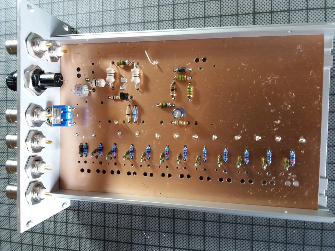
The distribution block consists of the following components:
- Input with 90V arrester & 100 kOhm MOX resistor to dissipate static interference
- Remote power supply, switchable, 10-14 V, max. 350 mA
- Amplifier stage with 14-14.5 dB
- Resistor network for distribution
The device is characterized by a very smooth frequency response and has a very low inherent noise. It offers the possibility of using levels of -120dBm with very good SNR
to process up to strong levels of up to + 14dBm. In addition, the reception on VLF is now possible, which did not work with the previous system.

The PCB is designed in a very practical way: series resistors for LEDs are integrated as well as fixing points for coaxial cables. The remote power supply can be switched separately, but can also be used permanently by means of a jumper.
With this concept, the distribution block can be used universally: use on an active or passive antenna with distribution to several receivers, by means of a step switch in front of it also for several antennas; if you leave the remote feed path unconnected, the block can also be used as a simple distributor, so it is almost universal for hobby purposes.
For use on SWL camps, we decided to install them in 19 “rack-mount technology. A standard rack can thus accommodate 4 distributors and a power supply, allowing distribution of 4 antennas to 12 outputs each. An example of the installation is shown in the following picture: Parallel to the input is another BNC socket, which is connected via a C 100 nF where the input signal can be used DC-free for measurement purposes or the like. The distribution unit is installed in a transport case. The components themselves are mounted in slide-in housings which are provided with a corresponding front panel: Such front panels might be obtained from CNC manufacturers.
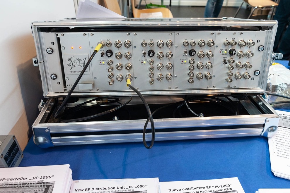
On the back + 12V DC must be supplied as operating voltage. For the power supply units, we opted for linear power supplies because we have made the best experience with these without interference. For a distribution unit with 4 slots, a power supply with 12V 1A is sufficient – each distribution block takes about 55 mA, an active antenna up to 150 mA, so even with “full load” a power supply with 1 A is sufficient. The distributor was tested with various well-known active and passive antennas, including a PA0RDT MiniWhip, active loops, long wires and T2FD.
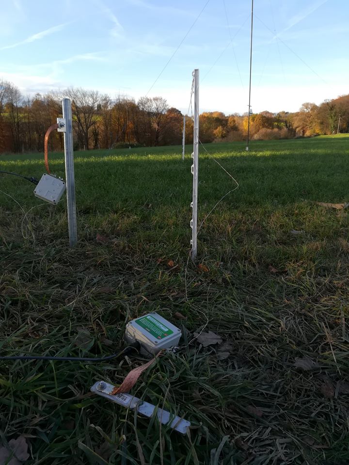
Due to the wide input voltage range, the module can handle nearly any antenna. The cost for a distributor for 4 antennas amounts (depending on the version: housing, sockets, switches, power supply, etc.) to about 700-1000 €. That may seem a lot at first glance. However, taking into account that a simple 5-gang distributor from mass production costs already around 250 ¬, the cost of the distribution of 4 antennas to each up to 12 outputs are not that much. The Friends of Radio NRW use two of these distribution units for SWL camps.
If you are interested in building one, please contact the author ([email protected]) for further information. The development history of the distribution unit is also available at www.dx-unlimited.eu.
Wow! What a beautifully engineered antenna distribution solution, Joachim! I love how you worked together to sort out all of the requirements for your system then build it for ultimate performance and flexibility. No doubt, you and your colleagues at Radiofreunde NRW posses a lot of design and engineering skills! Simply amazing and thank you for sharing your design with the radio community!
Contact Joachim for more details and check out notes and discussion at www.dx-unlimited.eu (may require registration).