Category Archives: QRP

Let’s hit the field with the new lab599 TX-500 Discovery QRP transceiver!

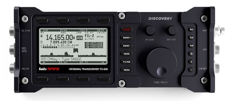
Yesterday, I took delivery of a lab599 TX-500 Discovery QRP transceiver. Many thanks to Josh at Ham Radio Crash Course for shipping it here and Ham Radio Outlet for trusting me with this fine machine for the next couple of weeks.

I’ve been looking forward to this day for months–indeed, nearly a year.

A few initial impressions…

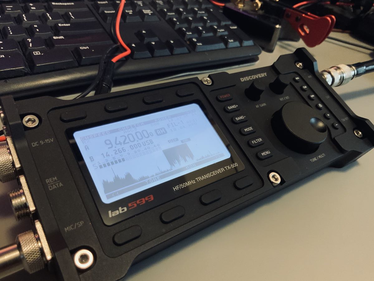
I won’t lie: the TX-500 is a gorgeous little transceiver and it’s solid.

The form factor is even a little smaller and lighter weight than I had imagined. I thought the multi-pin connectors on the side panels were the same size as, say, an XLR connector. Turns out, they’re much smaller and quite easy to use.

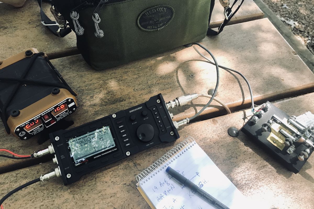
To put the TX-500 on the air, you’ll need to connect a minimum of three things: the power cable (terminated with Anderson Power Poles on the battery side), an antenna (BNC), and the speaker microphone. The TX-500 has no built-in speaker.

That’s all you’ll need if operating SSB. If operating CW, of course you’ll need to connect your key, but you’ll still need the speaker/mic connected for audio. That does make for quite a few things connected to the radio all at once.

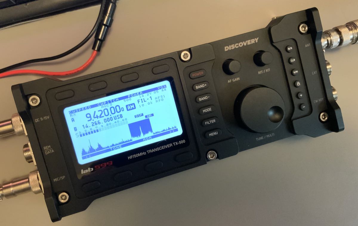
The backlit display is high-contrast and easy to read indoors and in full sunlight. (And yes, that’s the Voice of Greece!)

In the spirit of full disclosure, I am not a fan of speaker microphone combos, but I’ll readily admit that the one with the TX-500 is about as good as they come. It feels durable and produces serious volume. The audio fidelity is obviously built around voice and CW, so it’s not ideal for HF broadcast listening, although it does have an external mono speaker port on the side of the mic.

If I owned this TX-500, I would order another speaker/mic 6 pin connector and build a headphone cable for broadcast listening and CW use. An easy fix.

For SSB though? The provided speaker/mic works. Indeed, it works quite well in the field because it’s so easy to hear.

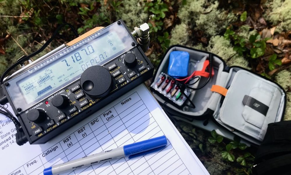
There’s so much more to this radio, but I’ll save that for future posts and my full review. Let’s talk code…

Attaching a key

This morning, the first thing I did was fire up my soldering iron and make a CW paddle cable. (I hope HRO doesn’t mind–I didn’t exactly think to ask. Come to think of it, let’s just keep this between us, ok?). 
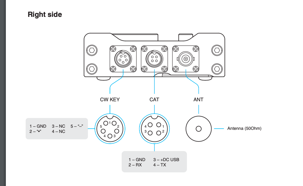
I soldered three wires to the supplied 5 pin connector (pins 1, 2, and 5).

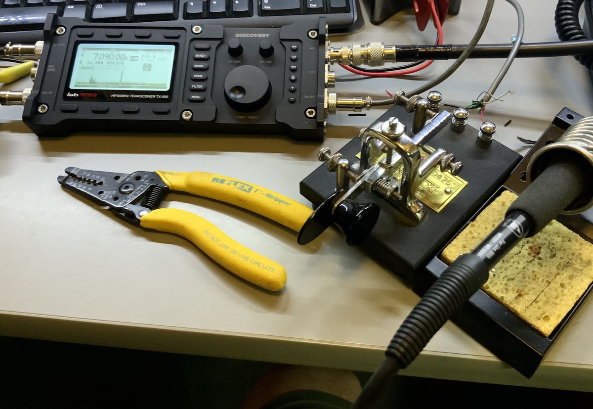
To keep things simple, I hooked the TX-500 up to my Vibroplex single lever paddle which sports three terminals, making it easy to connect to the CW cable pigtail. Plus, heck, any excuse to play with the Vibroplex, right!?

CW

I was so eager to see how the TX-500 would perform on CW, that immediately after hooking up the key the first time, I checked POTA spots and worked two stations (WR8F in Ohio and NG5E in Texas) in rapid succession. Here’s a video of the exchange with NG5E:

Note that I used my iPad to make this video and, for some reason, the mic accentuated the clicking/clacking of my Vibroplex key. It’s not normally that pronounced. 🙂

CW memory keying

One of my complaints about the TX-500 when I read the final feature list a couple weeks ago was that it lacked CW memory keying. To me, this was a major negative because many POTA and SOTA activators rely on CW keyer memories to help with their logging workflow in the field. I certainly do.

lab599 must have been listening because I found out last week that they implemented CW memory keying in the most recent beta firmware update. Woo hoo!

I was sent the firmware file and this morning had no issues installing it in the TX-500 with the firmware application/tool.

After I sorted out how to record and play back the CW memories using the top row of function buttons, I was ready to hit the field!

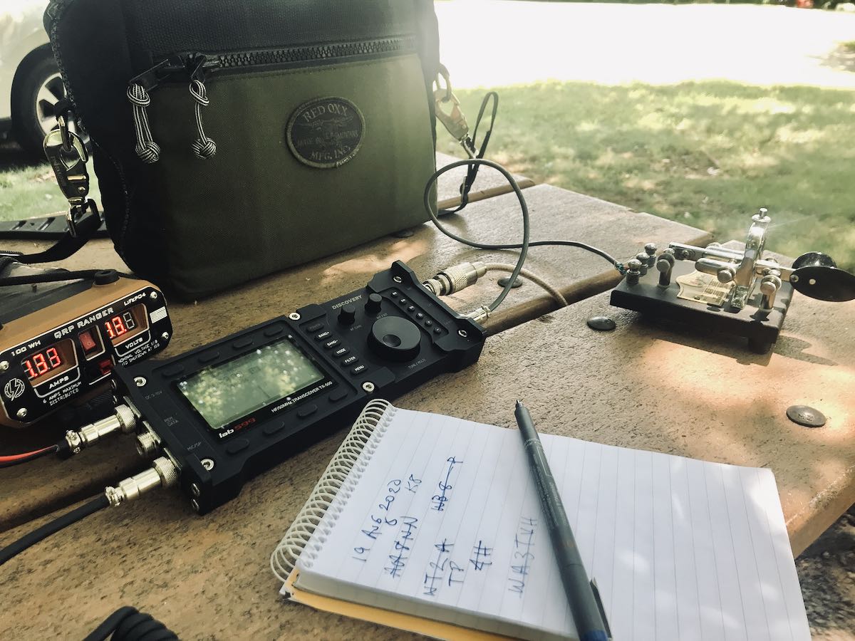
I packed the TX-500, and headed to the Blue Ridge Parkway for a POTA activation!

CW POTA activation

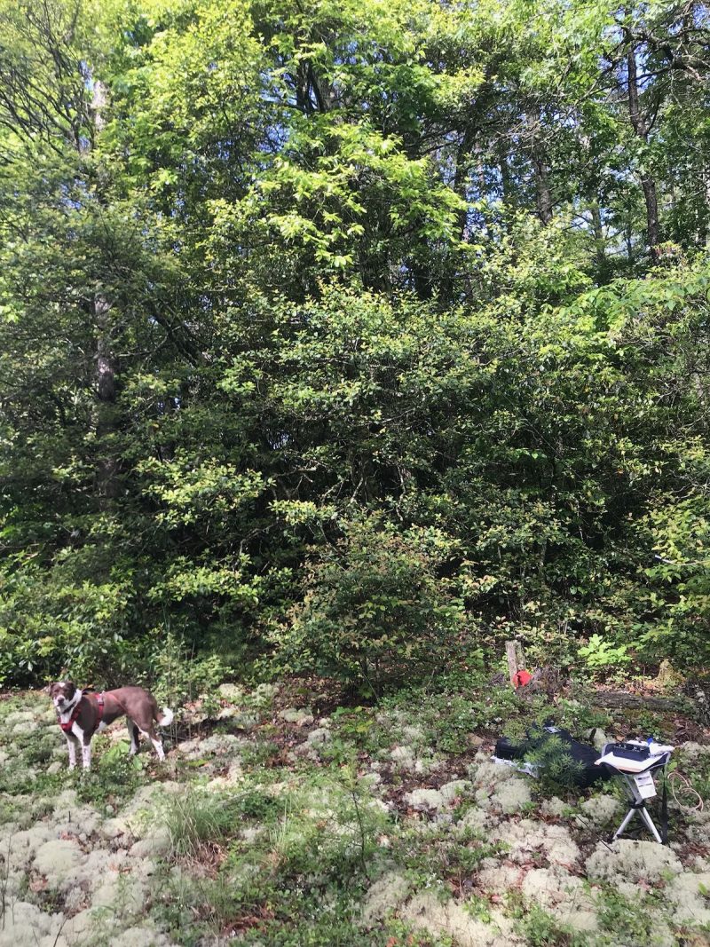
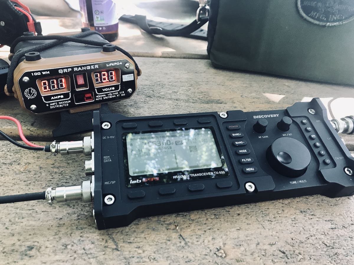
I only had a brief period of time to fit in an activation today, so I kept it simple by going to the Folk Art Center which has a number of picnic tables. A park ranger once asked that I not hang an antenna in a tree at this particular site, so I used my Wolf River Coils TIA portable vertical antenna.

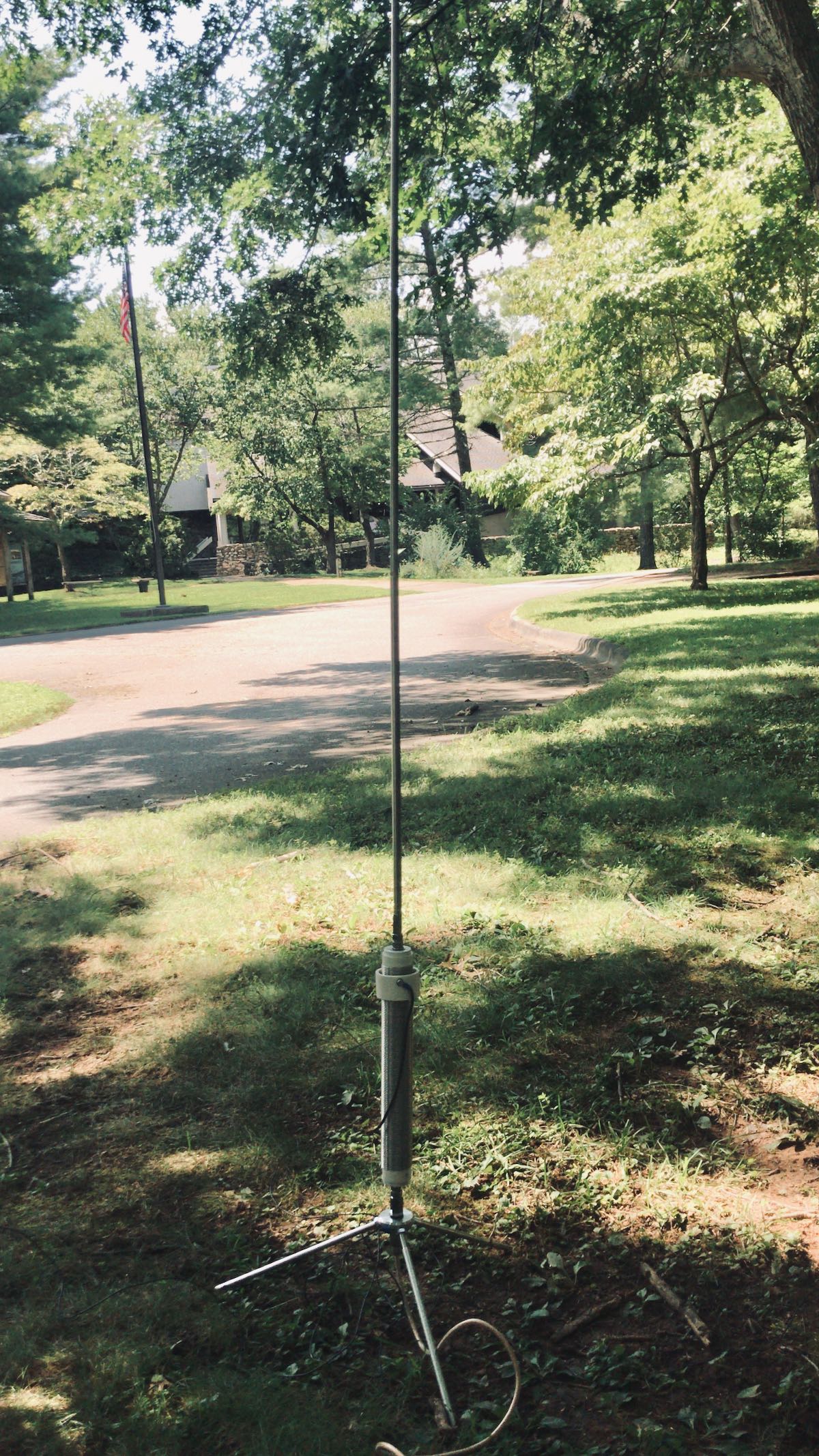
The Wolf River Coils TIA

Truth is, I feel like I always get more mileage out of a wire antenna than a vertical when running QRP, but I worked with what I had.

I started calling CQ on 7063 kHz and within 10 minutes worked five stations.

The CW memory keyer worked well. There is currently a two second delay before the TX-500 begins transmitting, but I’m guessing that can be fixed in a future firmware update.

Here’s a short video of the TX-500 memory keyer in action:

The TX-500 uses a relay to switch between transmit and receive, so you can hear clicking in the background. I had the recovery time set to the shortest interval which resulted in the maximum amount of clicking. Good news is the TX-500 body is so solid, the clicking is quite soft and muted–about the softest clicking I’ve ever heard in a transceiver. You could, of course, minimize relay clicks by setting the T/R delay to a higher number.

I’m very impressed with the TX-500’s low noise floor and filtering. Signals just seem to pop out of this thing.

I played radio for a while longer but was eventually chased off by a thunderstorm.

I must admit: for the first time, I wasn’t terribly worried if it started raining and the radio got a bit wet. The TX-500 is weather-resistant so can certainly cope with a sprinkle.

More to come!

I’ve set a personal goal to take the TX-500 to the field seven days in a row. I’m not entirely sure that’s realistic as I see the amount of thunderstorm activity in the forecast. Still, one must have goals, right? Plus, any excuse to hit the field and play radio!

Please comment if you have questions about the TX-500. I’ll do my best to answer as many as I can!


Do you enjoy the SWLing Post?

Please consider supporting us via Patreon or our Coffee Fund!

Your support makes articles like this one possible. Thank you!

Spread the radio love

Andy builds a genius companion control display for the Yaesu FT-817 transceiver

Many thanks to SWLing Post contributor, Andy Webster (G7UHN), who kindly shares the following guest post:


Yaesu FT-817 companion display

by Andy Webster (G7UHN)


Like so many I love getting out portable with my FT-817 but I do seem to spend so much of my operating time fiddling through the soft-keys because my most used functions (CW narrow filter, power and keyer settings to tune an ATU, A/B, A=B, etc.) are spread across different “pages” of the A,B,C assignments. Compared to the sublime experience of using my Elecraft K2 the FT-817 can be a little frustrating!

Last month, inspiration struck and I thought I could cobble together a small microcontroller and a little OLED display with some buttons to provide some extra soft-keys for the radio using the CAT serial port. Nothing particularly original here (I’ve seen articles of people using PICs for this purpose) but it seemed like a nice sized project for me to play with and build some experience doing PCBs (I’ve only done this once before at home). A little bit of discussion with Michael G0POT (FT-817 and SOTA guru), some Google searching and we were looking over KA7OEI’s excellent reference page (http://www.ka7oei.com/ft817_meow.html) and thinking about our favourite FT-817 commands…


As it happened I was lucky to have the right bits (Arduino Nano, small OLED display, buttons, prototype board and an 8-pin mini DIN cable) lying around the house to see “first light” from my FT-817’s serial port that evening. The Arduino Nano is a good place to start because it works at 5V so can work directly with the FT-817 levels on the ACC port. What followed next was some late nights of hacking on Arduino code to send and receive the data for my favourite commands and more experimentation on prototype board.

I tried a couple of cheap OLED displays and they look great indoors but weren’t quite up to the job in full sunlight which is fairly typical in my portable operations.

Daytime readability issues with an OLED display

By this point I had also realised the utility of having an auxiliary display on top of the radio as a much easier thing to view than the 817’s own display on the front panel. I’d also experienced some interference from the unshielded prototype board coming through as clicking sounds on the radio’s receiver so it looked as though some isolation between radio and my circuit might be necessary. Guided by many Internet tutorials, I switched to using a Nokia 5110-style LCD for better daylight readability and lower power consumption. Adding an ADUM1201 digital isolator and a B0505S-1W isolated DC-DC converter to the prototype board (modules acquired very quickly from eBay suppliers) gave me some isolation and lowered the interference which I guessed would disappear when I made the design on PCB with good ground planes around the signal lines.

Screen capture showing the schematic (click to enlarge)

With a (mostly) working prototype it was time to hammer the Internet tutorials again, this time to learn how to use KiCad, a free open-source PCB design tool available on Linux, Windows and Mac. I’ve done one PCB for home projects before using Autodesk EAGLE and I found learning Eagle pretty hard going, it seems like it carries 20 years worth of baggage and dogma in the user interface. In fact I started using EAGLE on this project but spent 3 hours on the first evening just trying to change the labels on the ADUM1201 chip that I couldn’t find in an EAGLE library… so I gave up and thought I’d try KiCad which I’d seen some recent good reports on. I’m happy to say after finding an excellent tutorial on KiCad I had drawn the schematic and my PCB layout in about 15 hours working time spread over a few evenings.

I should add that the 15 hours of KiCad time did include several hours of agonising over the choice of slide switch so a PCB can be done much quicker than that once you’ve got your favourite parts sorted!

That’s pretty impressive for my first go with KiCad as a near-beginner to PCBs, I heartily recommend it, it was so much easier than EAGLE and quite an enjoyable tool. Right, PCB design done and uploaded to JLCPCB for manufacture. 5 PCBs with DHL shipping cost me less than £20 and arrived from China within 5 calendar days. Other PCB fabs are available… 🙂

Click to enlarge

So that brings us to today, pretty much. The PCB was assembled very quickly (!) and there is no sign of noise from the serial data lines creeping into the 817’s receiver now it’s on PCB. Some lessons have been learned through the construction (e.g. brown 6mm push buttons are less “clicky” than the black ones and that’s a good thing!) and I now have my companion FT-817 display/buttons in field trials. I’ve no plans to sell this, it’s a trivially simple design, but it does make a great home project to polish your skills in microcontrollers, PCBs and construction. I’ll post a write-up on my website in due course.

In use, the device works just as I’d hoped, I can do everything I want to on my FT-817 without having to fiddle through the awkward button presses. The frequency display is also in a much better position for me now (as most FT-817 owners will know as they jealously eye the KX2, KX3, etc…!) and I think I used it for the whole session when I took it to the field on Saturday. If only my CW had been so slick!

Next steps are to work on the Arduino code. My code is pretty rubbish (my coding style involves a lot of Stack Overflow and copy/paste!) and not safe for public consumption. There are also some health warnings to be noted in manipulating the FT-817’s EEPROM (required for some of the functions I wanted), explained on KA7OEI’s page but there have been a few volunteers on Twitter to help with the software which is great. Also I may do a “Rev 2” board with an Arduino Pro Mini to lower the drain on the FT-817 battery before sharing the PCB files. Other than that it’s now time to get back outdoors and enjoy the new improved interface to my smallest radio! 😀

73
Andy G7UHN


Andy, I absolutely love this project! A wonderful addition to the FT-817/818 and I’d hardly call it a “trivial” design–!

I purchased the original FT-817 shortly after it was introduced. At the time, I was living in the UK and travelled extensively throughout Europe. I loved the ability to simply throw this little rig into my carryon and play radio pretty much anywhere my work travels took me. In the end, I did less ham radio work with the FT-817 and more SWLing.

Still, I eventually sold my FT-817 for the very same reason that motivated you to build a companion display: the front panel is too small and my most used functions require too much menu digging. 

Your companion board is an elegant homebrew solution. I love the Nokia LCD screen–superb readability in the field. 

Thank you again and once you do a write-up on for your website, we’ll be sure to link to it on the SWLing Post!


Do you enjoy the SWLing Post?

Please consider supporting us via Patreon or our Coffee Fund!

Your support makes articles like this one possible. Thank you!

Spread the radio love

Video: Josh takes us on a tour of the lab599 Discovery TX-500 QRP transceiver

Many thanks to SWLing Post contributor, Josh (KI6NAZ), who shares a link to his YouTube channel where he takes us on a tour of the lab599 TX-500 Discovery:

Click here to check out Josh’s channel, Ham Radio Crash Course on YouTube.

Thanks for sharing this, Josh! The TX-500 is certainly a unicorn in the world of field-portable QRP radios since it’s designed to be weather-proof.

lab599 has confirmed that they will dispatch a TX-500 loaner unit for my upcoming review.  I’m looking forward to see how it plays in the field and might compare with other QRP rigs in my arsenal!

Spread the radio love

The lab599 Discovery TX-500 QRP transceiver price and anticipated delivery via HRO

This evening, I discovered that HRO now has the long-awaited lab599 TX-500 transceiver available for purchase on their website.

I had actually placed an order for the radio, but I’ve asked to cancel it because I should have a loaner available for review.

Without a doubt, the TX-500 is one of the most anticipated QRP transceivers this year. Field operators have always wished for a rugged, weather-resistant portable radio and the TX-500 looks like it will fit the bill! Based on some of the videos we’ve seen, it should perform as well.

Click here to check out the TX-500 on the HRO website ($789.95 US at time of posting).

Update: HRO informs me that the lead time, or anticipated delivery is still weeks away.

Spread the radio love

Adding CW mode to the EA3GCY DB4020 Dual-band 40 and 20M QRP Transceiver Kit (Part 2)

Many thanks to SWLing Post contributor, Frank (ON6UU), who shares the following guest post which expands upon his previous DB4020 article:


The EA3GCY DB4020 transceiver now has CW mode

by Frank Lagaet (ON6UU)

After telling you all about the DB4020 SSB build I’m here with the CW part of the kit,  let’s say this is part 2.  At a certain moment Javier let me know the CW interface kit was ready for shipment and some week later it was delivered to my QTH.

Again, a well packed kit arrived in a brown envelope, components and boards well packed in bubblewrap.  I found even a board I did not expect which can hold a push button,  a switch and the connector for your morse key.  Javier thinks of everything it seems!

Unpacking the bubblewrap gave me this result,  all components in 2 bags.  In the bigger bag another 2 bags with 2 printboards,  one for the CW interface,  one for the CW filter.  Great !!  Checking the material bill resulted in all components there,  another thumbs up.

I started, of course, immediately building it because I wanted CW in the transceiver as soon as possible.  I don’t do much in SSB mode anymore and I already started missing CW on the DB4020,  so I started my KX3 to listen to while I was populating the boards.  I never thought CW was going to have this impact on me! …. ..

I started building the CW interface,  again starting with all small items.  I soon saw that the 2 relays which need to be soldered in were ideal to protect all components when the board is upside down, so I soldered them in very quickly.  I then soldered in all other components ending with the elco’s.

Next phase was the CW filter.  This board is small and came together in a blink of an eye, no problems there, the long legs of the 3 and 4 pin headers went in last.

The following day, I made all wire connections and soldered a 13pin connector,  leaving one pin out since I want to have the option to choose the width of the CW signal I’m listening to.  By cutting the FL CW + pin and adding an additional switch, I have now 500Hz or 2400Hz.  Great option, for very little effort and simple.  Another thumbs up here.

Now it was simply a matter of inserting the sub boards in the main board and all should be working.  And it did!  Hurray!  The 500Hz filter works perfectly,  filtering away all above or below stations nearby my operating frequency.

This is the result of the soldering work,  2 small boards which need to be inserted in the main board:

The CW interface still needs the 13pin header of which I cut one pin and mounted a switch to have the 2400Hz width.

The IC you see in the middle of the CW interface is the KB2 keyer which gives you several functions like 4 memories and beacon mode.  The 4 potmeters are used to set the level on 40 and 20 meters,  to set the delay between TX and RX switchover and to set side tone monitor level.   The keyer also provides functions as keyer mode A or B,  straight key function and can be set for speeds between 1 and 50WPM.   WPM speed can be set in 2 different ways.  Handy!

Here a picture of the CW filter inserted on the main DB4020 board.

The CW interface is inserted at the side of the main board,  notice the 2 wires which go to the switch to allow switch-over between 500 and 2400Hz.

(Wiring still needs to be cleaned up in this picture.)

Finally, the result:  a good working multimode QRP transceiver with 2 bands.  It should be possible to make close to medium range with it as well as DX,  even with QRP power.

And while I was building I also made a new key for this radio,  it is made out of a relay and cost nearly nothing,  looks good doesn’t it ?  hihi.

Homebrew key

The key, when in practiced hands (fingers hi), can do 50 WPM without a problem. My friend HA3HK does without blinking an eye at 40WPM with this kind of key and tells me that he can go faster if needed.  Me? I’m going it a bit slower.

Battery pack

As this radio is only using little power (0.4A in RX,  1 to 2A in TX depending the power you set it) I thought,  let’s make a battery pack for the radio.

The first plan was installing it in the box.  I did not do that because the batterypack is also powerful enough to feed my KX2 and other QRP transceivers. Since I can use it with all of them, a loose battery works out better for me.

I started with an old laptop which had a broken screen and some other malfunctions,  but still had a good battery,  although I needed the battery connector of course.  A piece of wood to mount the connector on was my next goal.  And since I still have another laptop using the same batteries, I can charge the battery without problems.  Simple, but good and it weighs much less than a gel cell battery.

The battery provides me with 12.5V and some 5Ah.  Enough to last for hours on RX and for sure good enough to activate 2 SOTA sites in one day.   It doesn’t look great but works great– that is what matters and to test it was more then good.  Next will be getting the battery pack in a nice box.  Better to re-use stuff than throwing it away I’m thinking.

I need to do something about the cover of the OLED display,  there is still some work there to make it look nicer.

Some video can be seen on YouTube :

Finallym I’d like to thank you all for reading my articles about the DB4020. I had big fun soldering, tinkering with the box, making the key, and batteryholder/batterypack.  My Hungarian friend HA3HK told me it looks a bit like a spy radio. …. ..

I also include one more time the link where you’ll find this kit :

https://www.qrphamradiokits.com/

73 TU ee

Frank

ON6UU


Thank you so much, Frank. No doubt, you had a lot of fun putting this excellent little kit together.

Implementing a filter switch was a fantastic idea and, obviously, not terribly difficult to do.

Based on the videos, the DB4020 has a low noise floor and very good receiver characteristics. I’m impressed that the CW portion of the radios has so many features as well, such as a memory keyer and beacon mode.

I also love how you reused that 5Ah laptop battery! I think that could almost give you a full day of SOTA activations at those consumption levels!

Thanks again for sharing this with us, Frank! We look forward to your future articles!

Spread the radio love

Radio in the field: Two new POTA activations this weekend!

This past weekend my wife suggested that I do a Parks On The Air (POTA) activation. I think she wanted me out of the house so that she could prepare a birthday and Father’s day surprise with my daughters.

Of course, I happily obliged. My motto in French: “Profitez-en bien!” or “Make the most of it!”

Hazel (our dog) made it crystal clear she wanted to join me as well. She’s a great hiking companion and also watches out for black bears while I operate in the forest!

DuPont State Game Land (K-6902)

I decided to activate the DuPont State Game Land which was about a one hour drive from my house. Not only was it a new park for me, but it was also an ATNO (All-Time New One) for the POTA program.

I arrived onsite around 10:15 AM local and the parking lot for the forest trail heads was already packed.

It was a gorgeous day and this part of the DuPont Forest is well-known as a great mountain biking spot. I was very lucky to find a place to park.

We’re still in full social distancing mode in North Carolina due to Covid-19, so I had no desire to be anywhere near other people. Hazel and I went off-trail and hiked in about 1/4 of a mile to a nice clearing.

I set up the EFT Trail-Friendly end-fed antenna and operated with the Elecraft KX2.

I called for quite some time before I was spotted in the POTA system. After being spotted, I quickly racked up more than the required 10 contacts for the activation to be considered valid.

Although the weather was amazing and my antenna deployment was near-ideal, the bands were rough and unstable, so it was challenging.

Hazel and I packed up, moved out, and made a detour to visit a waterfall near a site I hope to activate in the near future. Here’s a short video:

Kerr Scott State Game Land (K-6918)

Since Sunday, I’ve been visiting my hometown to help my parents with a few projects.

Yesterday, I had a four hour break in the day and decided to, of course, benefit from the beautiful weather and activate another new-to-me site. (Can you tell I’m addicted to POTA?)

I picked the Kerr Scott Game Land because it was “only” a 50 minute, rather scenic, drive.

It was quite easy finding a spot to park.  Like most game lands, though, you must be prepared to go through off-road conditions. Part of the driveway into the site was incredibly muddy and definitely required at least all-wheel drive.

I set up my station in the shade and easily deployed the end-fed antenna once again.

Lesson learned

This activation of Kerr Scott Game Land taught me an invaluable lesson: if you don’t have a “spot” of your activation on the POTA site, it’s like you don’t exist.

The POTA spotting network (much like popular DX spotting networks and clusters) is simply amazing. As a POTA hunter, you open the spots page and you’ll see a list of all of the current operators, their park numbers, and frequencies where last heard.

As an activator, your number one priority when you find an available frequency and start calling CQ is to be spotted on the POTA network.

If I have good mobile phone coverage at my site, I self-spot on the network. Within a few seconds of the spot posting, I’ll typically have a pile-up of a few operators trying to reach me.

If I have cell phone service, but no data, I’ll text my good friend Mike (K8RAT) and ask him to spot me on the network.

Kerr Scott, like most game lands, however, had no mobile phone service whatsoever, so I had no way to self-spot. In fact, this particular site was a good 15 minute drive from the nearest cell phone signal.

I called CQ for 30 to 40 minutes on my announced frequency, at the announced time, but not one single op come back to me.

Since I had just driven 50 minutes to reach this site, there was no way I was going to give up so easily. I had already set up my station in the trunk/boot of my car, so I simply secured it, disconnected the antenna and tied it to a tree branch (so it wouldn’t be in the way), and drove 15 minutes to a spot where I could send a quick message to Mike.

When I got back to the Kerr Scott, I hooked up the antenna, made one call, and had a pile-up of five operators I worked in rapid succession. In fact, I had my required 10 contacts within 8 minutes.

I do wonder how some of the most adventurous POTA activators manage to post spots while in remote areas. It’s such a key component of having a successful activation, I wonder if they use a satellite phone or satellite messaging device to text a friend for help. (If you’re a POTA or SOTA activator, I’d welcome your comments here!)

At any rate, I was very pleased to hammer out an activation so effortlessly once I was spotted on the network.

The CW secret weapon

I should add here that CW activators have a secret weapon that’s incredible effective: the Reverse Beacon Network (RBN).

As a CW operator, the POTA spot system will read your callsign from the RBN as long as you have made an announcement on the POTA website in advance or have already been spotted to the POTA website. All you have to do is set up your station at the site and call CQ: the POTA system will auto-generate an accurate spot for you based on the frequency from the RBN.  It’s incredibly effective and more than enough reason for me to think I should start doing CW activations.

I can operate CW–in fact, I routinely make CW contacts in POTA and in other contests. However, I’m not quite brave enough to call CQ from a POTA site and work my way through even a modest pile-up.

I need to practice CW more, and I will!

This week, I also take delivery of my Wolf River Coils TIA antenna. I’m looking forward to having the TIA as an option when I need a self-supporting antenna that’s quick to deploy and can handle up to 100 watts when needed.

Post readers: Did you play radio in the field this weekend? I’d love your comments–especially if you simply took a receiver outdoors to enjoy some noise-free broadcast listening!


Do you enjoy the SWLing Post?

Please consider supporting us via Patreon or our Coffee Fund!

Your support makes articles like this one possible. Thank you!

Spread the radio love

Building the EA3GCY DB4020 Dual-band 40 and 20M QRP SSB Transceiver Kit (Part 1)

Many thanks to SWLing Post contributor, Frank (ON6UU), who shares the following guest post:


Building EA3GCY’s DB4020 QRP Transceiver kit

by Frank Lagaet (ON6UU)

In May, I discovered via a newsletter that a new kit was available from Javier EA3GCY in Spain.  I was immediately sold as this was a kit from my favourite kit producer and it has 2 bands–it will also be able to do CW and there also will be a CW filter.

After building 2 MFT’s from Javier which work without problems, I needed to have the DB4020.  The MFT’s are for 20 and 40 mtrs and do DSB (double side band).  I did put them in a not-so-graceful box but they do what they are intended for which is QRP phone (SSB).   They came together without problems so I expected the same for the DB4020–I knew for sure when I saw the board:  all through-hole components (except for some capacitors which are factory soldered) and a lot of space on the board.   The board has been silk-screened with clear indications on where all components have to come and the manual has very clear instructions where each component has to be soldered with referral to a quadrant.  The manual provides a 252 quadrant page so it is a piece of cake to find where each piece goes.

What do you get?

Javier provides you with all components which need to be installed on the board and, of course, the kit board.  The components come in small marked plastic bags and all is well-wrapped up in bubble wrap.  The board is wrapped separately and that is put together with the component wrap which is then again wrapped up in bubble plastic.  All goes into an envelope.  Very well packed I must say.

Here’s a picture of the bags with components:

The silk-screened board:

I started with the resistors since that’s the easiest way. After that, I did the capacitors.  I like to solder in all flat components first, so next were the diodes and IC sockets followed by the elco’s.  The transistors were next together with all relays.  As you solder in the transistors one also has to mount the cooling heatsinks,  these cooling sinks are high and are ideal to protect the coils one has to make,  they also protect the polystyrene caps (which I always find vulnerable) when the board is upside down.

Many kit builders are afraid of winding the toroids in kits–don’t be!  It is easy.  Just take your time and follow the instructions given by Javier in the construction manual.  In this kit the builder has to wind 8 toroids:  6 are a single wire which goes through the toroid body,  1 is a toroid with 2 different windings, and 1 has a twisted pair which goes through the final toroid.  Be sure to measure the wire you need per toroid as instructed in the manual.  Javier gives some spare, so you can be sure.  You will also see that on next picture where the legs of the toroids have not been trimmed yet.  Once done I still had some centimetres of wire leftover.

Picture of the toroids ready to be soldered in:

Finally all other parts and pin headers went in,  jumpers were immediately put on where needed.

As I’m using a military-grade plastic box, I have to break-out some components like the display,  tuning encoder,  volume and rx control from the board.  I also have put an on/off switch on the box and already have the CW KEY connector ready installed. I also installed a loudspeaker in the box.  The SI5351 board and the Ardiuno Nano are the final components which go into the board after installing all wires.

Picture of the board:

I intend to attach a CW paddle to the box made out of a relay.  A HWEF tuner (from EA3GCY) which I was planning to incorporate in the box is I think a bit overkill. That HWEF tuner is already in a nice little box and would be a pity to dismantle,  also I’m running out of space in the box…  Maybe I can fit in a 9-1unun which would then give me good results on both bands…?

Maybe I will install a battery pack in the same box.

The box with board installed:

The box completed front side:

Mind you,  it still needs some additional switches for the CW part of the transceiver.

73
Frank (ON6UU)

Video


Brilliant, Frank! I really appreciate the video as well–sounds like the kit produces smooth audio and should serve you well. No doubt, that military box enclosure will survive even the roughest field conditions!

Click here to check out the DB4020 kit at EA3GCY’s store.

Spread the radio love