 Many thanks to SWLing Post contributor, Bill Hemphill, who shares the following guest post:
 YouLoop Antenna Fun
by Billy Hemphill WD9EQD
Like many listeners, I live in an antenna restricted community. While I have strung up some hidden outdoor wire antennas, I have found that they didn’t really perform that much better than just using the telescoping antenna with maybe a length of wire attached. The biggest problem (whether indoor or outdoor antenna) has been the high noise floor.
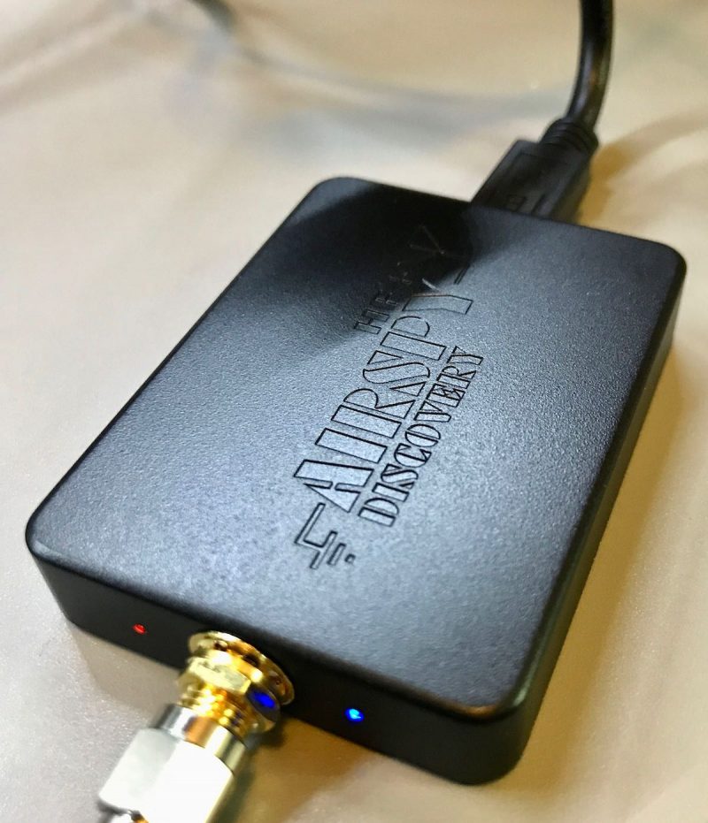
A few months ago I bought an AirSpy HF+ Discovery SDR receiver. I had already owned a couple of SDRPlay SDR receivers, but the high noise floor limited their performance. I had read good reviews about the AirSpy, especially its performance on the AM Broadcast band and the lower shortwave bands.
I have about 80 feet of speaker wire strung from the second floor and across the high windows in the living room. This does perform fairly well, but the high noise floor still exists.
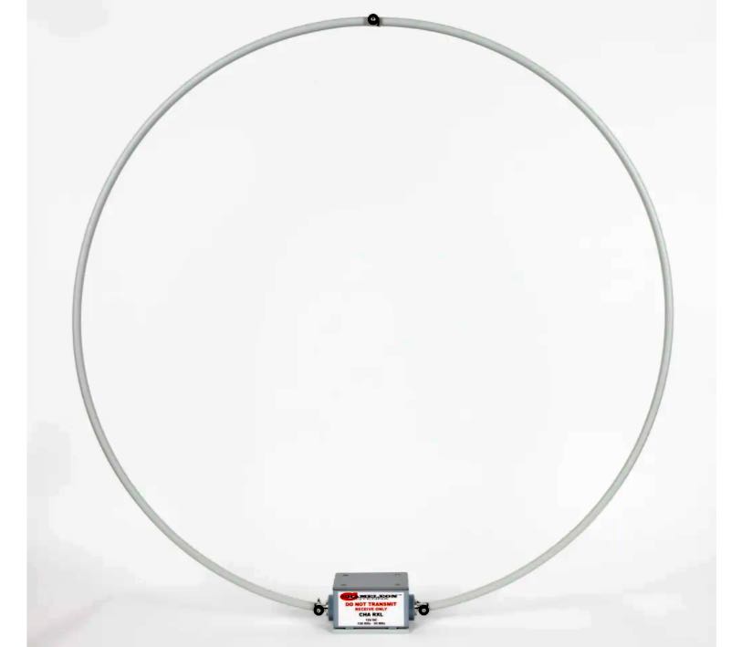
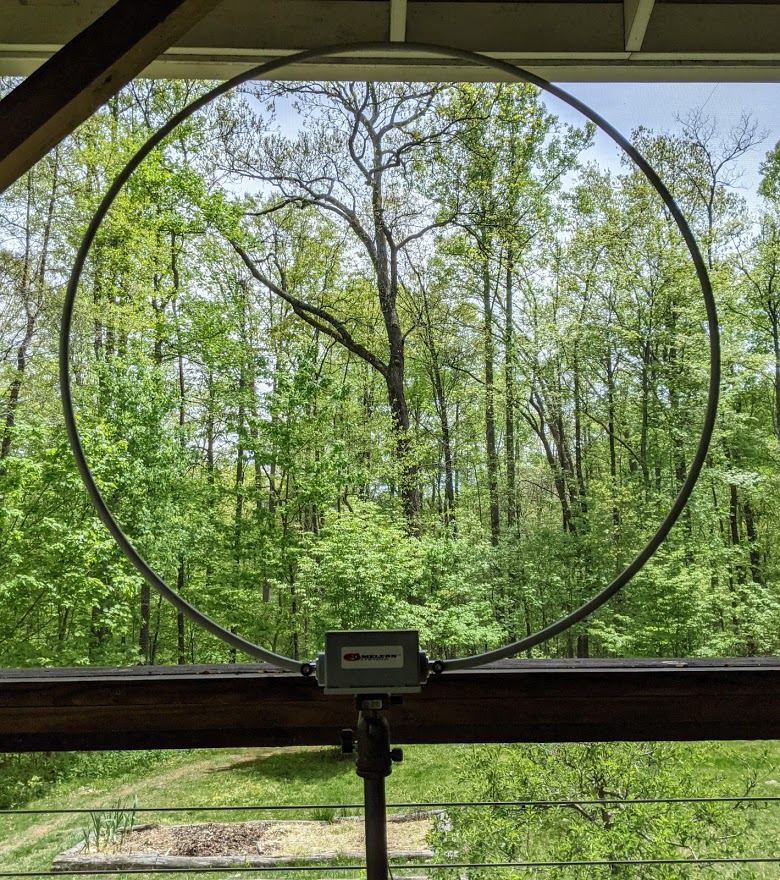
A couple of weeks ago, I bought the YouLoop Magnetic Loop antenna from AirSpy. I gave it a try and am amazed at the lower noise floor compared to the indoor wire antenna.
Wire Antenna vs. YouLoop–some examples:
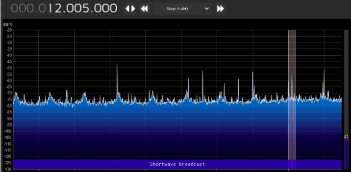
AirSpy with Wire Antenna

AirSpy with YouLoop

AirSpy with Wire Antenna
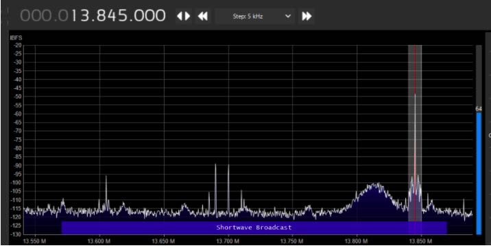
AirSpy with YouLoop
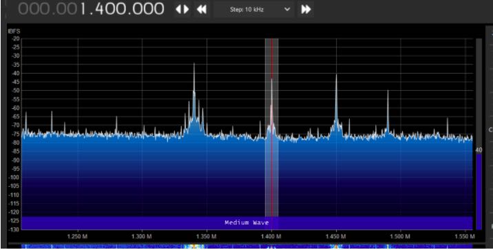
AirSpy with Wire Antenna
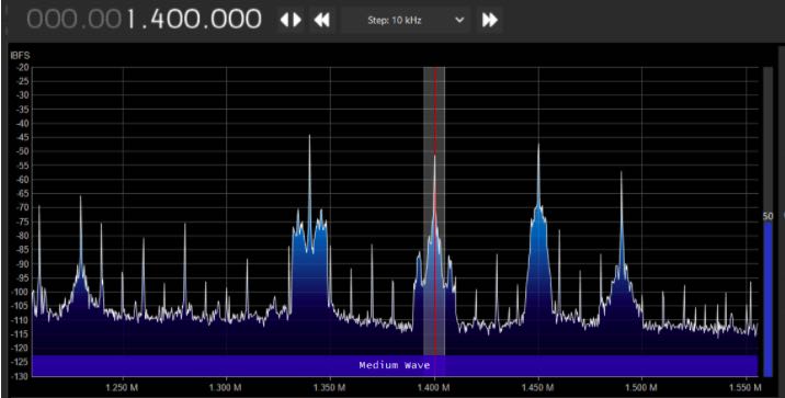
AirSpy with YouLoop
Dramatic reduction in the noise floor. I’ve done a lot of playing around with it and find that the YouLoop picks up just about the same stations as the indoor wire antenna does. But with the lower noise level, the YouLoop makes it more enjoyable to listen. Overall, the YouLoop is now my main antenna.
YouLoop with a Portable Radio
It works so well with the AirSpy, I started wondering if I could use it with a portable radio, like the Tecsun PL-880. But the AirSpy website has the following note:
Note: It is very likely your third party radio will not be sensitive enough to operate with the YouLoop properly. We have even seen self-documented failed attempts to build pre-amplifiers to compensate for the lack of sensitivity and/or the required dynamic range in third party radios. Use your brain, and eventually an Airspy HF+ Discovery.
Doesn’t sound like it will work with portable radios. BUT, I’m always one to try anyway.
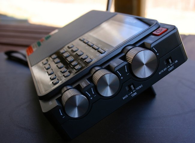
Tecsun PL-880
Since the YouLoop has a SMA connector, I bought a SMA to 1/8” phone jack cable. Plugged it into the PL-880 antenna jack and found I had almost a dead radio. Very few stations heard. But in playing around, I accidentally touched the phone plug to the telescoping antenna and instantly got strong signals.
I did some very unscientific tests. I attached the YouLoop through the side antenna jack, did an ATS scan, then did the same with the YouLoop clipped to the telescoping antenna. Also did a scan with just the telescoping antenna fully extended.. I got some very interesting results. These were done one after the other, so there can be differences in signal fading, etc.
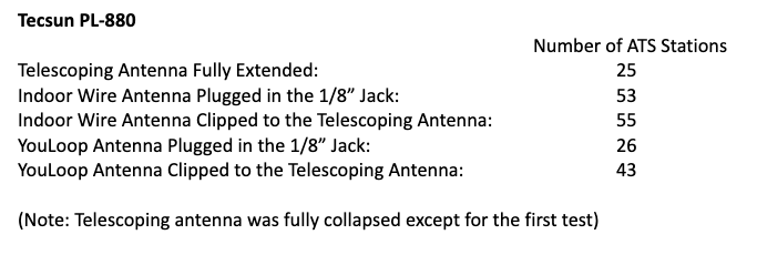
I have repeated the above test several times at different hours. While the actual number of ATS stations varied, the ratio between them remained fairly consistent to the above numbers.
From the above, it appears that the telescoping antenna circuit is more sensitive than the 1/8” antenna jack circuit. Maybe some attenuation is being added to the 1/8” jack since it’s more likely a higher gain antenna would be used there. Can anyone confirm that the circuit indeed attenuates thru the antenna jack?
The YouLoop seems to be a decent performer when directly clipped to the telescoping antenna. While not as good as a high gain outdoor antenna would be, it definitely is usable for indoor uses.
I also tested it clipped to the antennas of some other portable receivers. Tecsun S-8800, PL-330, Panasonic RF-2200 and Philco T-9 Trans-World receivers. All showed an increase over just using the telescoping antenna.
Some interesting notes:
The Tecsun PL-330 saw the same reduction in signal when directly plugged into the antenna jack as opposed to clipping on the telescoping antenna.
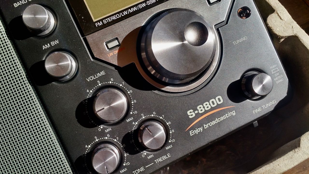
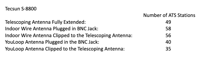
The Tecsun S-8800 did not show that much of a drop. I basically got the same number of stations when clipped to antenna as when I connected to the BNC jack:
 In conclusion, I find that I can use the YouLoop with my portable radios to increase the signals on strong stations when used indoors. And it is quite the performer when used with the AirSpy HF+ Discovery SDR receiver. It easily portable and I find that I move it around the house as I need to. I just hang it off a window curtain rod. I may just order a second one so that my family room radio has one permanently attached to it.
Click here to check out the Youloop at Airspy.com.

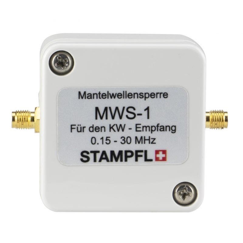
 Many thanks to SWLing Post contributor, Ulrich Ruch, who writes: