Category Archives: Shortwave Radio

RSGB 2018 Convention Lecture: DC to Microwaves on your smartphone

(Source: Southgate ARC)

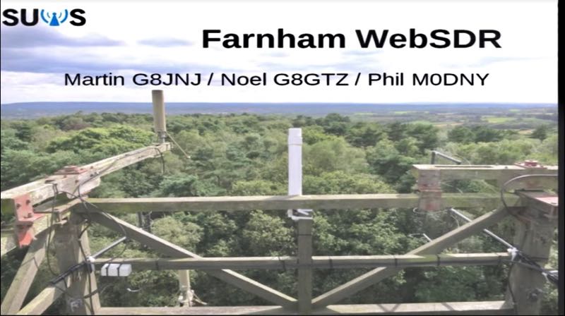
The presentation by Noel Matthews G8GTZ on the Farnham WebSDR given to the 2018 RSGB Convention is now available on YouTube:

Click here to view on YouTube.

This presentation gives an overview of the Farnham WebSDR, available at http://farnham-sdr.com/ which currently covers the LF bands through to 10GHz.

The presentation describes the system architecture and antennas currently used on each band and how the team has used RTL dongle receivers, available for under £10, to give good RF performance on all bands from DC to 10GHz. There is a demonstration of the SDR in use on both PC and smartphone.

First Look: Elecraft K4 photos and preliminary information

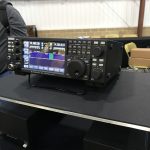
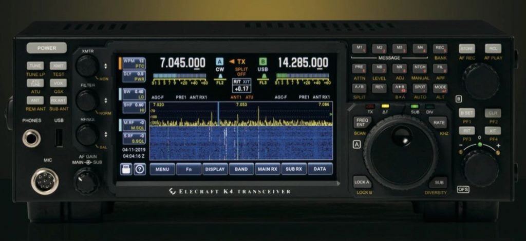
The new Elecraft K4

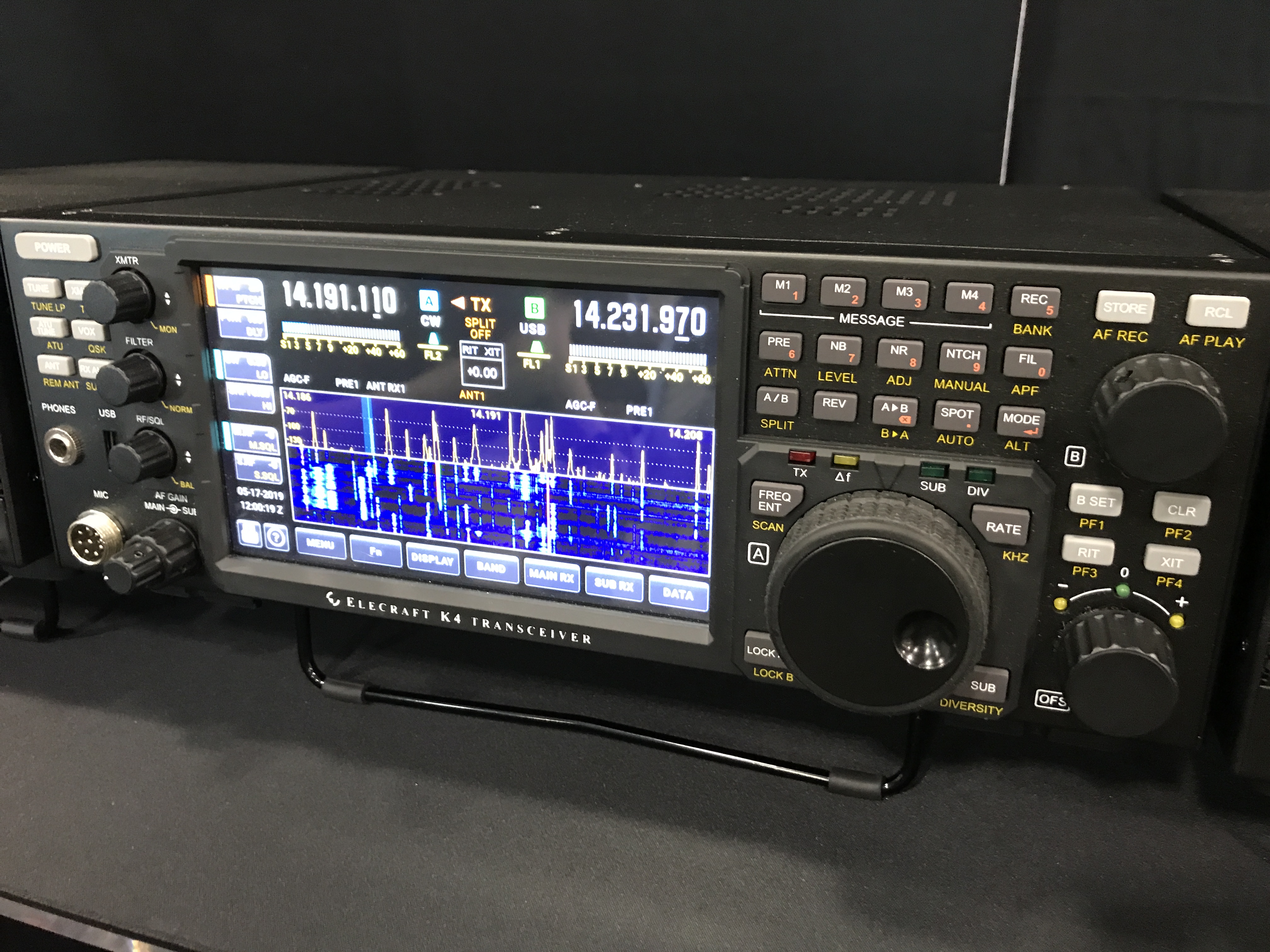
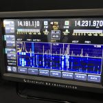
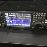
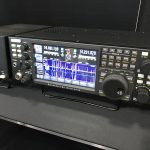
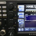
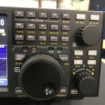
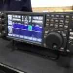
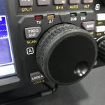
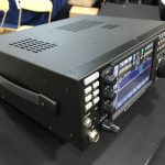
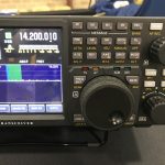
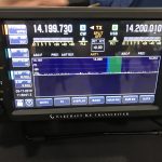
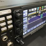
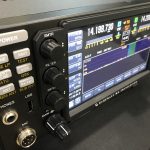
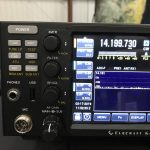
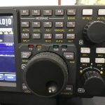
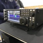
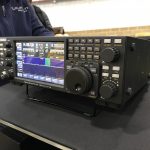
Today, prior to the open of the 2019 Hamvention, I had an opportunity to hang with the folks at Elecraft and grab some photos of their newest transceiver: the Elecraft K4 direct-sampling SDR (click here to read the announcement).

Elecraft has now published a K4 product page on their website with information about pre-orderswith information about pre-orders. In short, the base model—which includes two full receivers—starts at $3999 US.

Wayne Burdick told me that they expect to start shipping the K4 by the end of 2019.

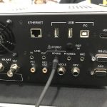
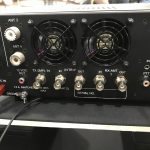
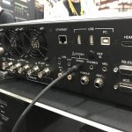
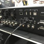
I snapped a number of photos of the two engineering prototypes of the K4 this morning in Building 1 at the 2019 Hamvention.

Elecraft K4 Photos

Click on the images below to enlarge:


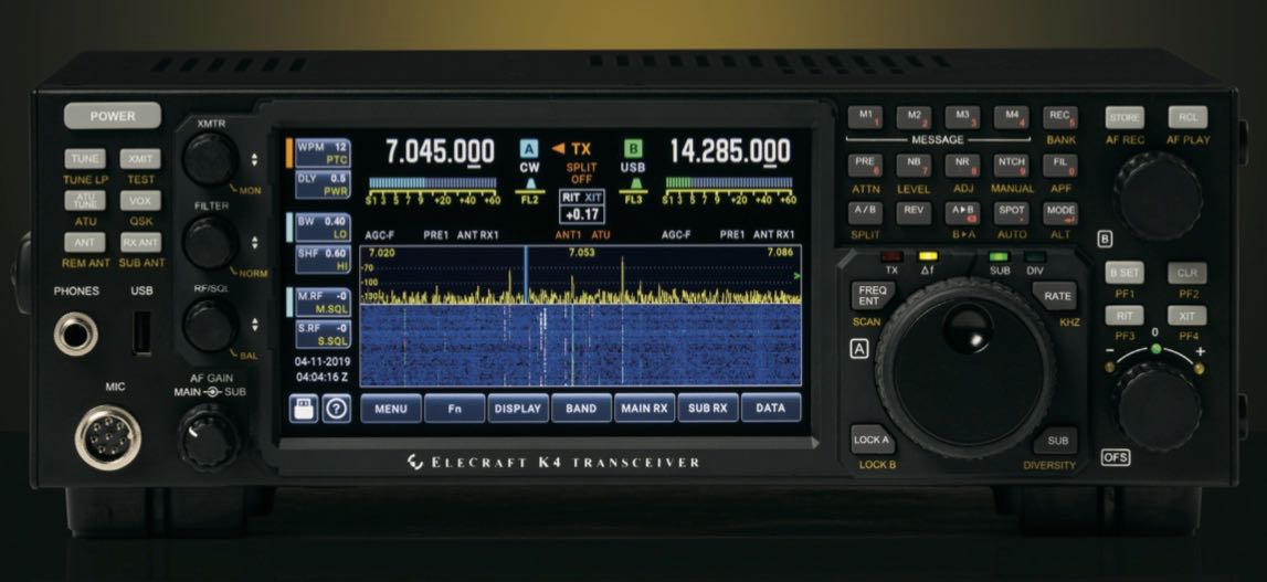
Elecraft introduces the K4 high-performance direct-sampling SDR

Click to enlarge (Source: K4 Product Brochure)

Today we learned about the latest addition to the Elecraft product line, the Elecraft K4.

This fills a niche in the Elecraft product line and is certain to directly compete with the likes of the Icom IC-7610 and a number of Flex Radio transceivers, among others.

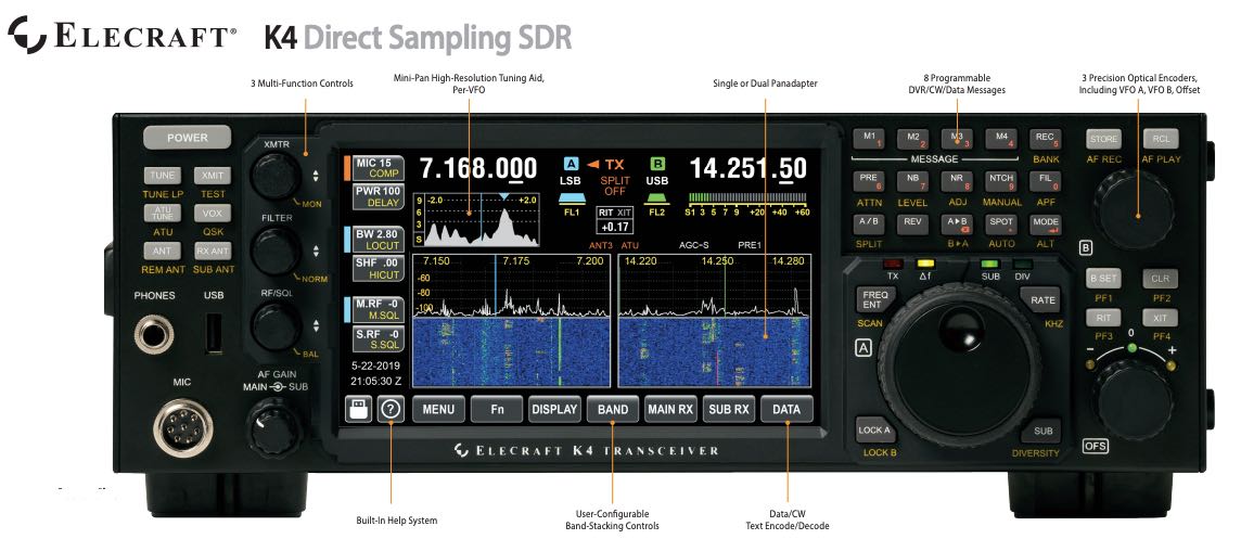
Elecraft describes the K4 as having a “modular hybrid architecture”. Below, I’ve pulled the text and images from the Elecraft product brochure.

Wayne Burdick (N6KR) of Elecraft notes that tomorrow (Friday, May 17, 2019) the Elecraft site will (re)launch a K4 product page with pre-order/reservation page.

I plan to learn more about the K4 and report back during Hamvention this week. Stay tuned by bookmarking the tag Elecraft K4:

Elecraft K4 Product Information

(Source: Elecraft K4 Product Information Sheet via Lutz Electronics, Switzerland)
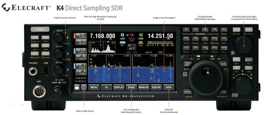
Click to enlarge (Source: K4 Product Brochure)

A direct-sampling SDR you’ll love to use

Our new K4 harnesses the latest in signal processing while retaining the best
aspects of the K3S and P3. The resulting user interface makes the technology
transparent, allowing you to focus on working the world.

160-6 meter, all-mode coverage & dual RX

The K4 includes dual receive over 100 kHz to 54 MHz. Since it utilizes direct
sampling, there’s no need for crystal filters in the K4 or K4D (see Models, back
page). For extreme-signal environments, we offer a dual superhet module
(standard in the K4HD). An internal VHF/UHF module is also planned.

High-resolution mini-pan for each receiver

Our advanced fine-tuning aid, with its resampled bandwidth as narrow as +/- 1
kHz, is displayed separately from the main panadapter. You can turn it on by
tapping either receiver’s S-meter or by tapping on a signal of interest.

Simple operation and setup

The K4 features a large, full-color touch display, combined with a rich set of real
controls. Per-VFO transmit metering makes split mode completely foolproof.
Band-stacking switches and per-receiver controls are both intuitive and versatile,
adapting to operating context. Usage information on these and other features
is just one tap away, thanks to our built-in help system.
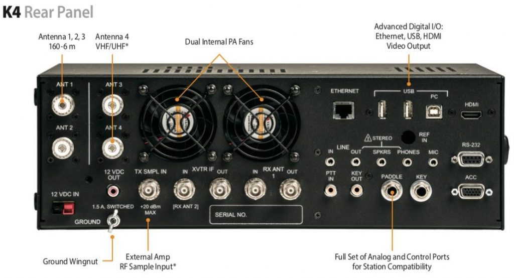
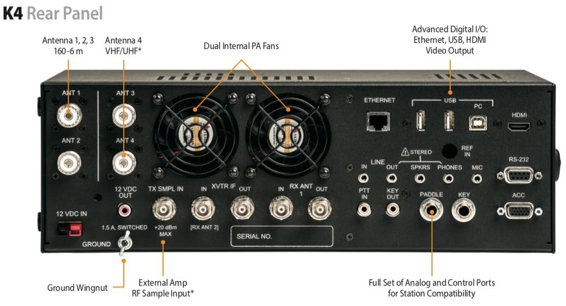
Click to enlarge (Source: K4 Product Brochure)

Rich I/O complement

The rear panel includes all the RF, analog and digital I/O you’ll need to complete
your station. All K-line accessories are supported, including amps, ATUs, and our
K-Pod station controller. The HDMI video output supports an external display
with its own user-specified format.

Full remote control from multiple devices

The K4 can be 100% remote controlled, via Ethernet, from a second K4 as well as
a PC, notebook, or tablet. Panadapter data is included on all remote displays.

Modular hybrid architecture

The K4 adapts to your needs, with three models to choose from:

  • Basic K4 with wide-range dual receive
  • K4D with diversity receive
  • K4HD with a dual superhet module for exceptional dynamic range

You can upgrade or add options as desired, or as new technology becomes
available. This extensibility applies to software as well. The K4’s powerful, fast-starting CPU provides unlimited expansion opportunities.

Fast signal processing

The RF signal chain in the K4 incorporates parallel hardware processing of data
streams, including a dedicated DSP subsystem. This, combined with silent,
PIN-diode T/R switching, ensures fast CW break-in. Data and speech-processing
delays are also minimized.
Standard DSP features include easy-to-adjust, per-mode RX/TX EQ; clean,
punchy RF speech processing; full DVR capabilities; and several built-in data
decode/encode modes. Direct-sampling technology results in an ultra-flat
passband response for clean RX and TX audio. Since the signal chain is softwaredefined, the DSP can be field upgraded to add new algorithms and operating
modes.

KAT4 ATU

The KAT4 ATU has a nominally 10:1 matching range. It includes 3 antenna jacks,
any one of which can be selected as an input for one or both receivers.

Internal VHF/UHF module (future option)

An expansion slot is reserved for a high-performance VHF/UHF module, with
output of approximately 15 W. This module will support all modes.

Kit version

A no-soldering kit version of the K4 is planned for later release. Builders will learn
about advanced radio technology as they proceed. All modules are pre-aligned
and tested.

K4 Key Specs and Features

  • Size: 4.5”Hx13.5”W,10”D
  • Weight: Approx.10lbs
  • SupplyVoltage: 12-15VDC
  • Current: ~2ARX,~18-23ATX
  • FrequencyRange: 100kHz-54MHz(VHF/UHFrangetobe determined*)
  • Stablility: +/-0.25ppm(TCXO) Modes: CW, SSB, AM, FM, Data
  • LCD: 7”color;touch&mousecontrol Text modes: CW, PSK31/63, RTTY KAT4ATU:
  • 10:1+range;3ant.jacks RXantennasources: Upto5
  • A-to-D Converter(s): 16 bits
  • I/O: USB-Ax3,USB-B(twovirtualcomports+audio),RS232(DE9), Ethernet, HDMI. front/rear mic, front/rear phones, LINE in/out, speakers,PTTin,KEYout,paddle,key, ACC,12Vout.
  • CWQSK: Silent,PIN-diodeswitched
  • Other: RX/TX EQ, real-time clock,100% remote control including panadapter data, remote antenna switch control*, custom in-box software apps*

Models (K4 & K4D upgradeable by the user at any time)

  • K4: Basic K4 transceiver provides 160-6 m, all-mode coverage; 100 W output; five receive RF sources; and wideband dual watch, allowing the main and sub receivers to be set for the same or different bands.
  • K4D: Adds KDIV4 option, with a second set of band-pass filters and additional direct- sampling ADC module. This allows the two receivers to use different antennas – a requirement for diversity receive. Having two sets of band-pass filters also optimizes signal handling when the receivers are on different bands and/or antennas.
  • K4HD: Includes all of the above, plus our dual superhet module, the KHDR4. Ideal for competitive field day, contesting, and DXpedition stations. Each superhet receive section includes two crystal filters: one SSB/data bandwidth, one CW bandwidth. The superhet’s 8 MHz IF has excellent dynamic range, so additional crystal filters are not required.
The Hermes-Lite SDR: an open source HF transceiver based on a broadband modem chip

Many thanks to SWLing Post contributor, Pete Eaton, who writes:

Don’t know if you are familiar with this project, a full blown 5 watt HF SDR Transceiver for less than $300!

No sound cards, DUC/DDC architecture.

Here’s the project description by Steve Haynal via YouTube:

The Hermes-Lite is a low-cost direct down/up conversion software defined amateur radio HF transceiver based on a broadband modem chip and the Hermes SDR project. It is entirely open source and open hardware, including the tools used for design and fabrication files. Over 100 Hermes-Lite 2.0 units have been successfully built.

The FOSSi Foundation is proud to announce Latch-Up, a conference dedicated to free and open source silicon to be held over the weekend of May 4th and 5th in Portland, Oregon, USA. Latch-Up: a weekend of presentations and networking for the open source digital design community, much like its European sister conference ORConf. Produced by NDV.

Click here to view this presentation on YouTube.

Fascinating! Thank you for sharing, Pete!

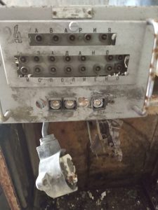
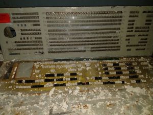
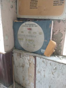
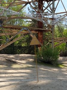
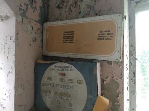
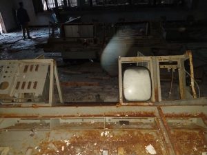
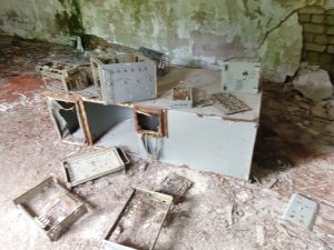
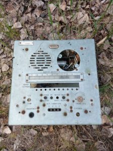
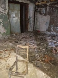
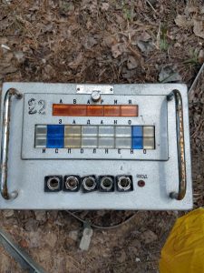
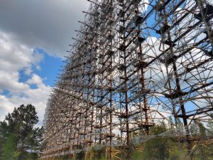
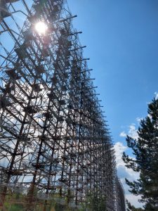
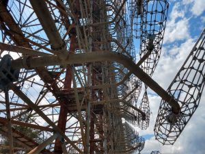
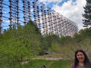
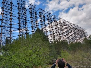
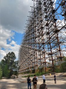
Photo Gallery: Stephen makes a pilgrimage to the Duga site

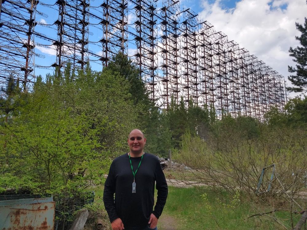
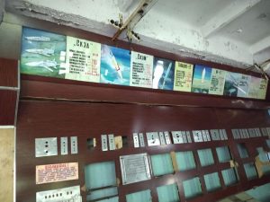
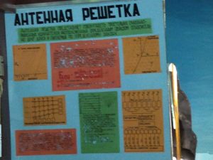
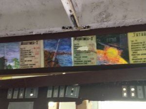
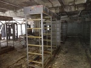
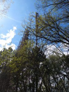
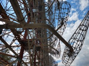
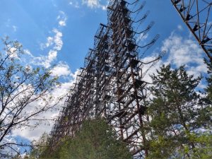
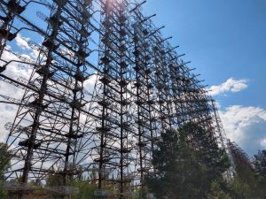
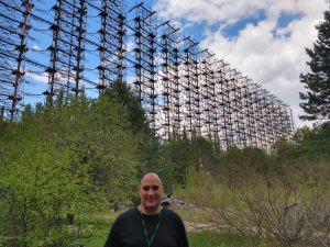
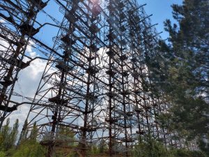
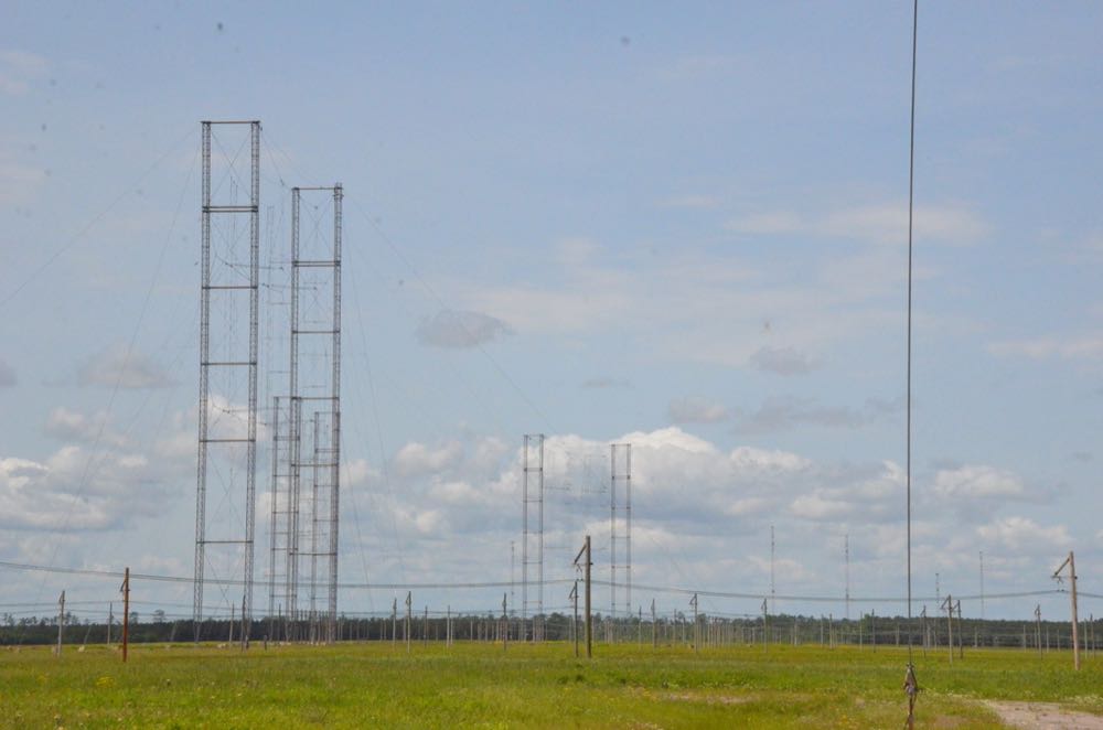
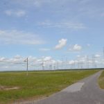
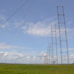
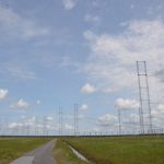
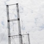
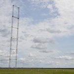
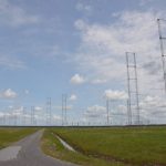
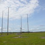
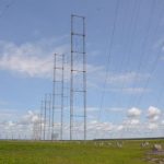
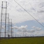
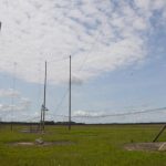
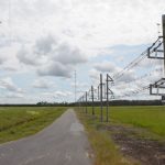
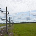
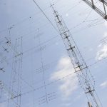
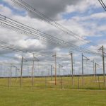
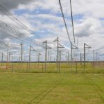
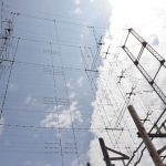
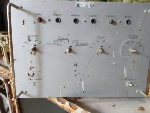
Many thanks to SWLing Post contributor Stephen Cooper who shares photos from his recent visit to the Duga Soviet Union era over-the-horizon (OTH) radar system near Chernobyl.

The following photo gallery contains images of the antenna, control room, training room and server room. Click on the thumbnails below to enlarge images and browse:

What an amazing site, Stephen! Thank you for sharing your photo tour with us.

Readers: Stephen is also an application developer and the kind fellow behind Shortwave.am, Interval Signal Ringtones for Android, and the Shortwave Radio Schedules app. Check them out!

Cyclone Fani: How Ashok prepared for this powerful storm

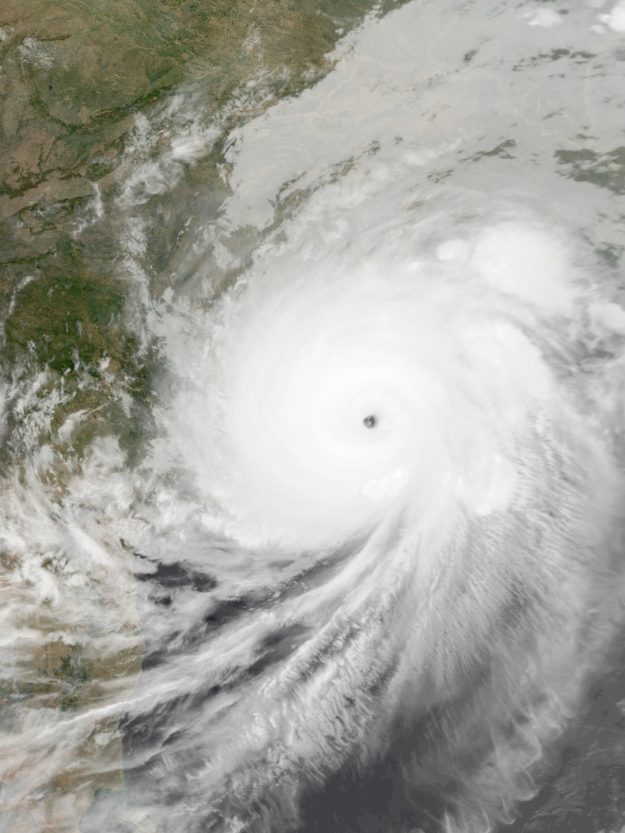
Category 4 Cyclonic Storm Fani was the strongest tropical cyclone to strike the Indian state of Odisha since Phailin in 2013.

Many thanks to SWLing Post contributor, Ashok Shankar Das, who shares the following post from his blog SWLDAS:

The extremely severe cyclonic storm #Fani recently visited Odisha. It is Peculiar to have a Cyclone in this time of year. Though history says earlier there are some cyclones hit Odisha coast during this summer season.

[…]I have seen several Cyclones including #1999SuperCyclone . Though Super cyclone has done a lot of damage, this one is no less. Wind speed of 200kmph with gust 220 to 250 kmph ripped everything in its path. major damages to infrastructures like power grids, cell towers under construction buildings are name a few.

My Preparedness

The CountyComm GP5-SSB

See this SWLING article–I was runner-up in that challenge. My preparation for Cyclone Fani was as per I have described. Well Not all. I have charged emergency light, arranged candles and lantern. Stocked Biscuits and Flat rice. Stored around 15Liters of drinking water. Emergency medicines and fully Charged 3 Baofeng Walkie Talkies.

The GP5SSB I got as a gift from SWLING Post, put new battery in it. I have downed external antennae for HF and VHF. Baofeng handys are quite good as scanner. I monitored HAM band so I could know the situation in surrounding area and also if situation arises I could give a distress call to Nearby monitoring person. But that situation didn’t arise.

HAM volunteers from WBRC started their communication service since 5th May. They Have setup a VHF in state control room at Bhubaneswar, ADM office Puri and Khurda.
Since 5th may onward I was monitoring and in QSO with VU2IPL(Suresh). VU2FTP VU2XRY VU3YDA and VU3OXI are handling the communication between Puri, Khurda and Bhubaneswar.[…]

Click here to read Ashok’s full post on his blog, SWLDAS.

Thank you for sharing this, Ashok and we’re very pleased that you made it through this extremely dangerous storm well-prepared. It sounds like your community has a good ham radio communications network at the ready as well.
Ashok, you are reminding me that it’s time to dream up another Virtual Radio Challenge along with an enticing prize. I’ll start putting one together! Perhaps I can find a prize at the Hamvention this week. Stay tuned…
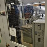
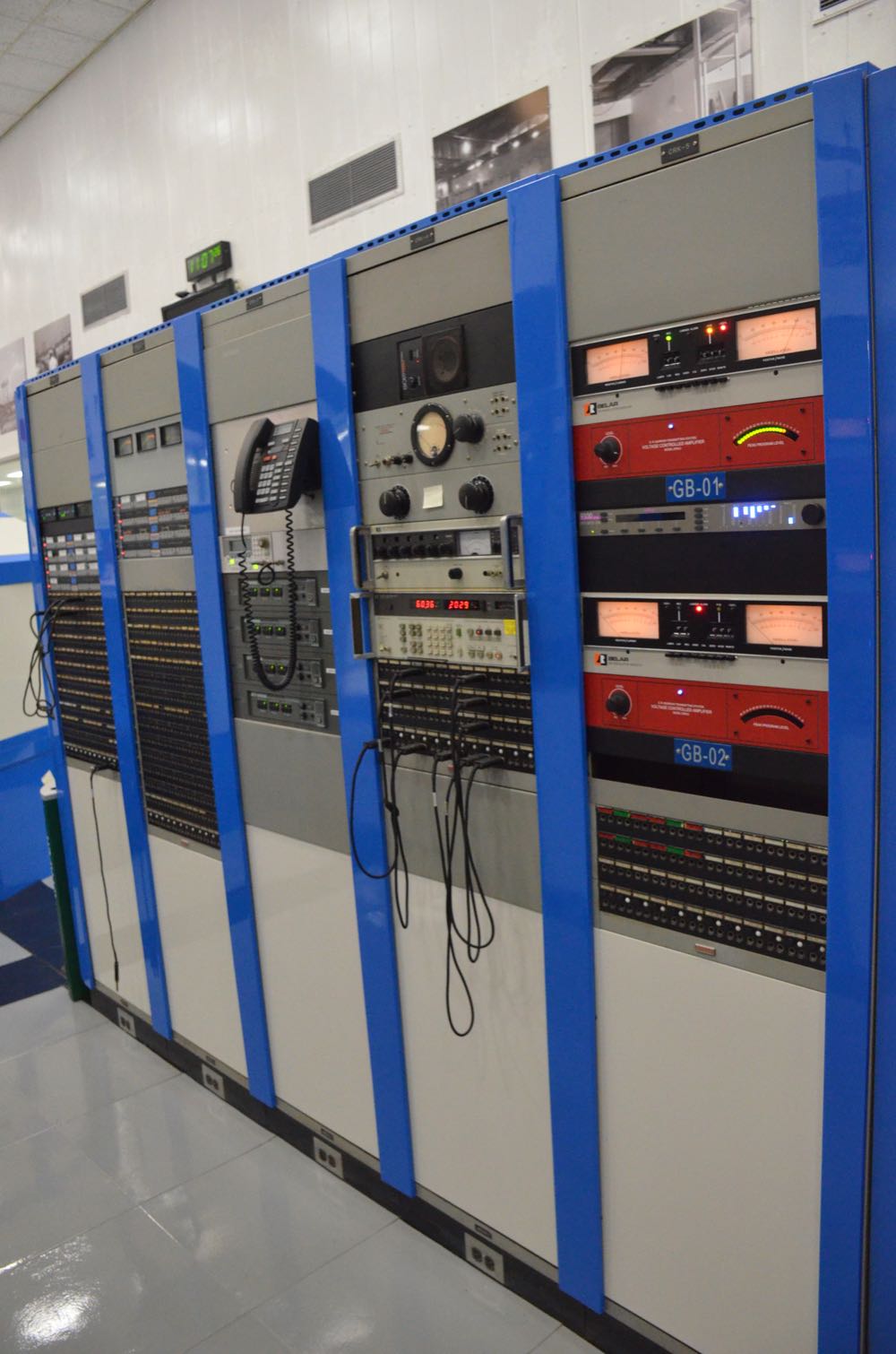
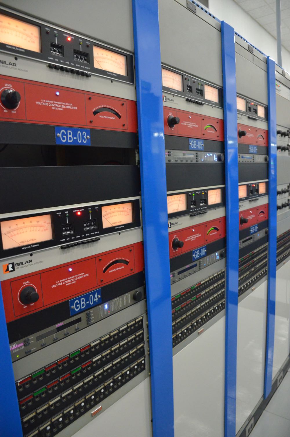
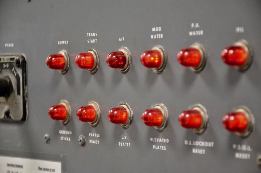
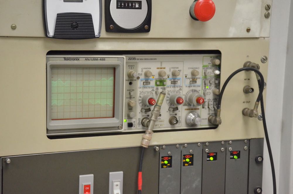
Photo Tour: The Edward R. Murrow Transmitting Station

Yesterday, I posted a photo and asked if you guess where I was when I took the shot.

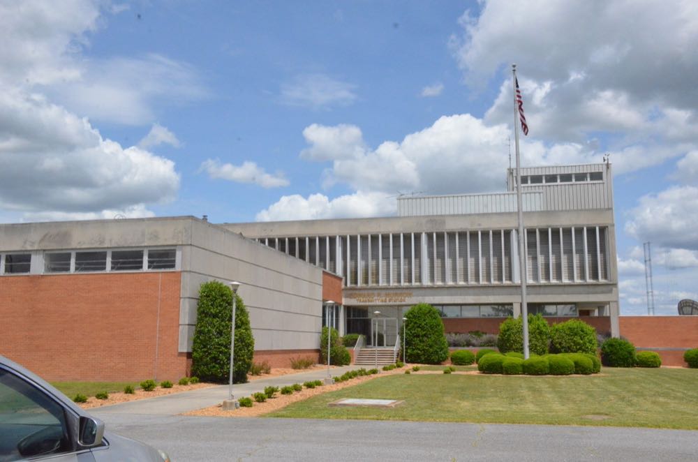
Those of you who guessed the Edward R. Murrow Transmitting Station (formerly, “VOA Site B”) near Greenville, North Carolina, were absolutely correct!

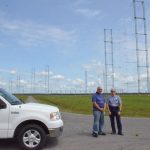
My buddy, John Figliozzi, gave a presentation about NASWA and the Winter SWL Fest at the NASB (National Association of Shortwave Broadcasters) which was held in the Raleigh area, May 9th and 10th. Due to a conflict, I was not able to attend the NASB meeting this year, but I did arrive at the conference hotel late Thursday where I met a handful of attendees. I had previously invited John to join me on the station tour, and he was quite happy to do so!

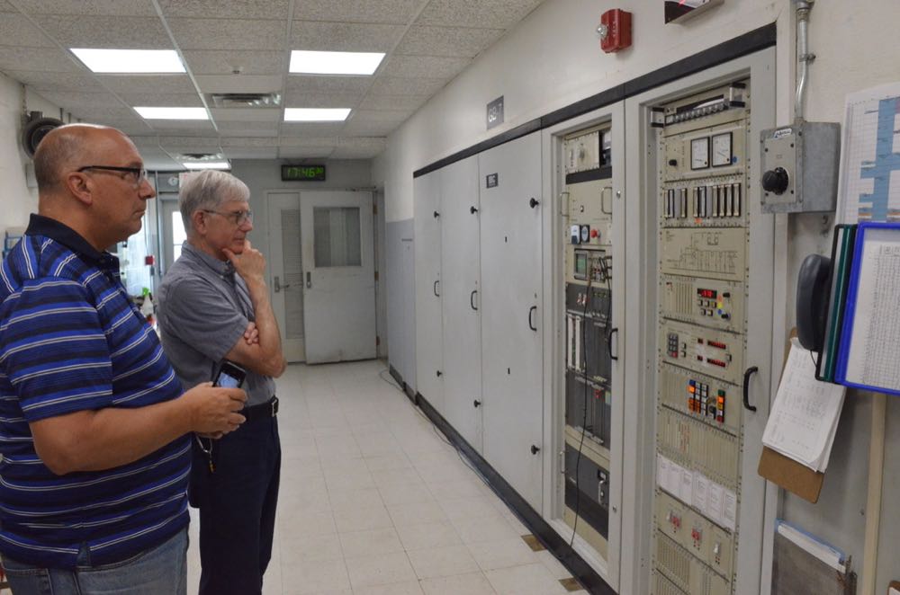
Macon Dail (WB4PMQ), the transmitting station’s Gold Medal award-winning Chief Engineer, made time to give us a tour Friday, May 10, 2019.

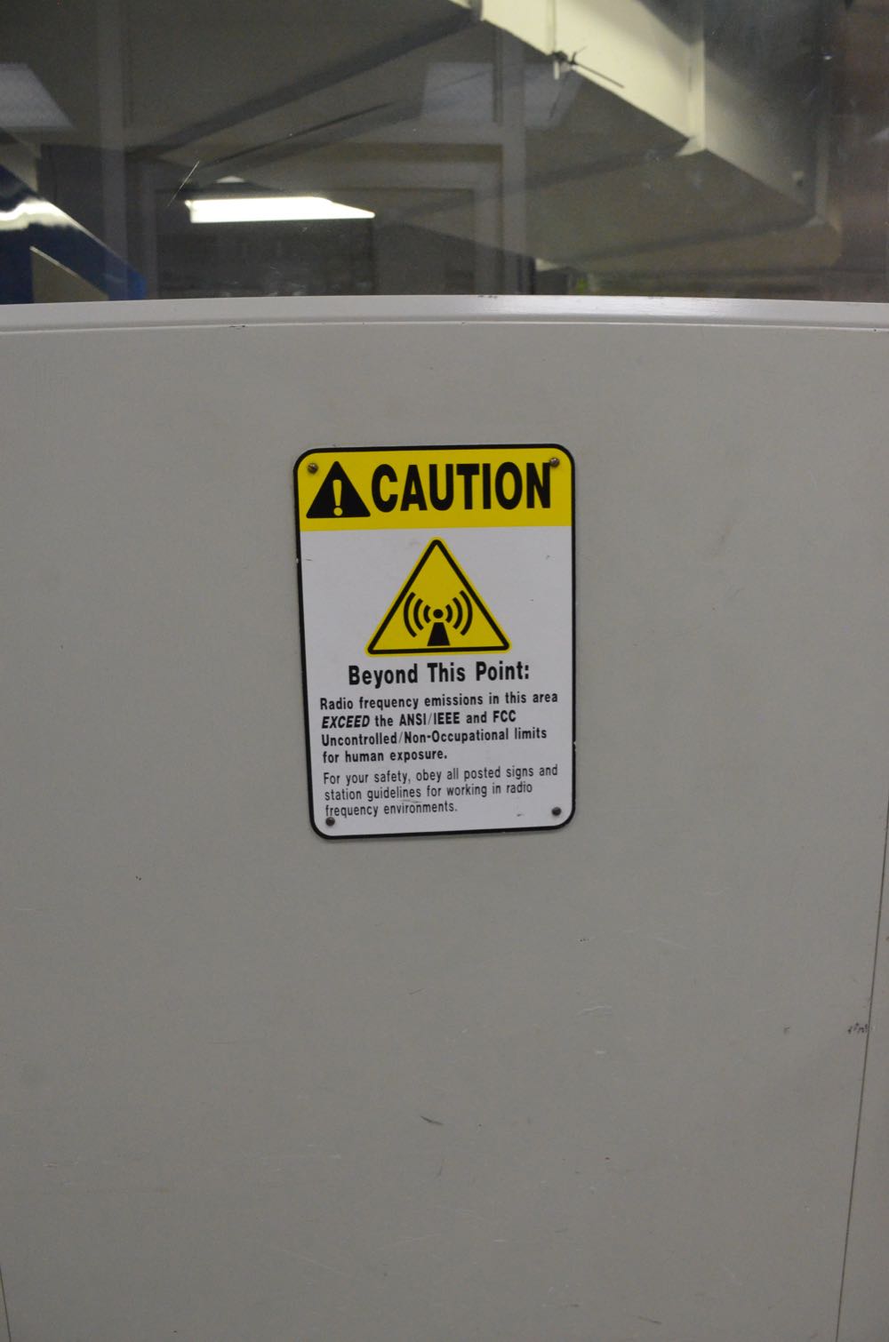
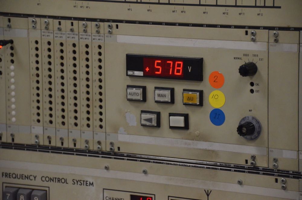
And now, on to the photo tour of this remarkable facility.  My inclination is to caption each photo…but I know if I attempt this, I won’t post this gallery for several months!  Instead, I’ll roughly divide the photos by the various sections of the site. Note, however, that there are more than one hundred photos in this detailed post––to decrease its length, some of the photos have been placed in clickable thumbnail galleries. Those of you who receive the SWLing Post as an email digest, I would strongly encourage you to view this post directly on our website, so all of the gallery images will appear.

Enjoy!

Station entrance, lobby, and library

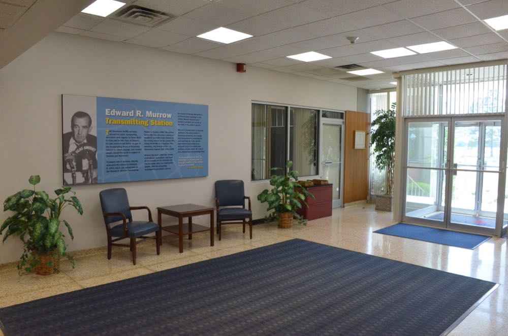
The Front Lobby

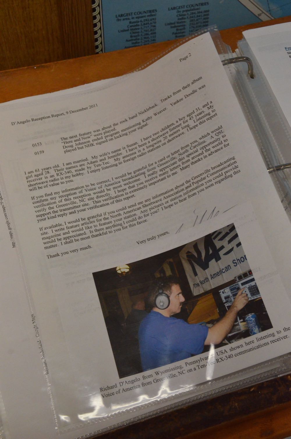
In this photo, Macon is showing John one of the notebooks, which is chock-full of reception reports from listeners. This notebook, as you can see, is prominently displayed in the front lobby.

We found our friend Rich D’Angelo in the stack of reception reports.

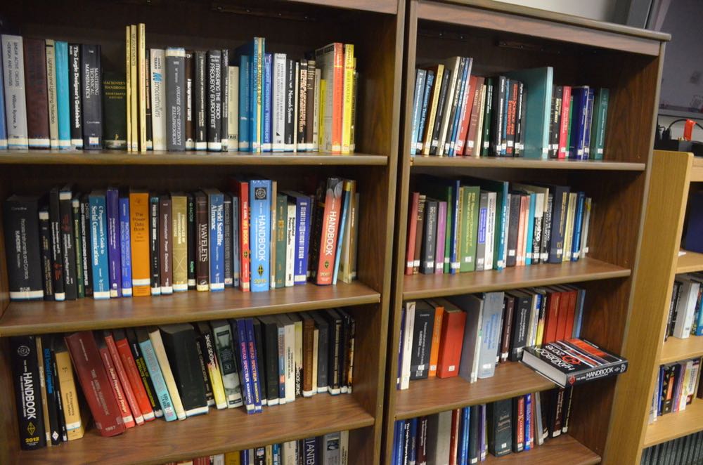
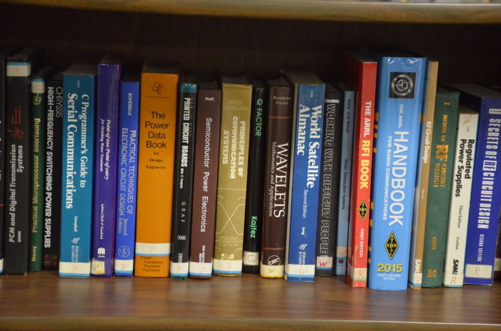
In a mezzanine above the control room, there is a space that houses a library, a presentation/classroom area, and even a small workout/fitness room.

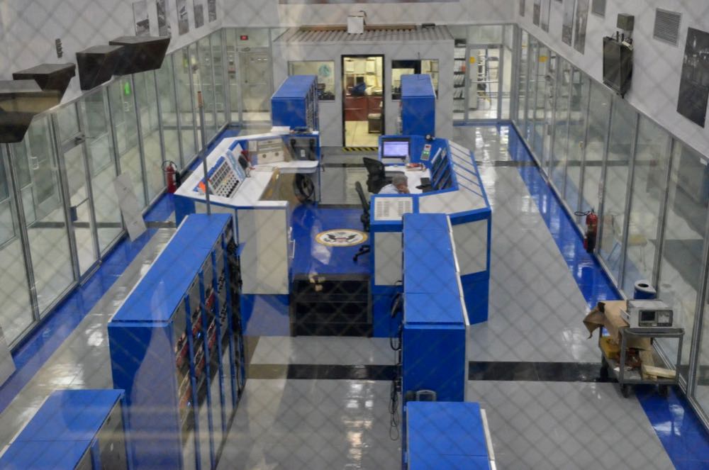
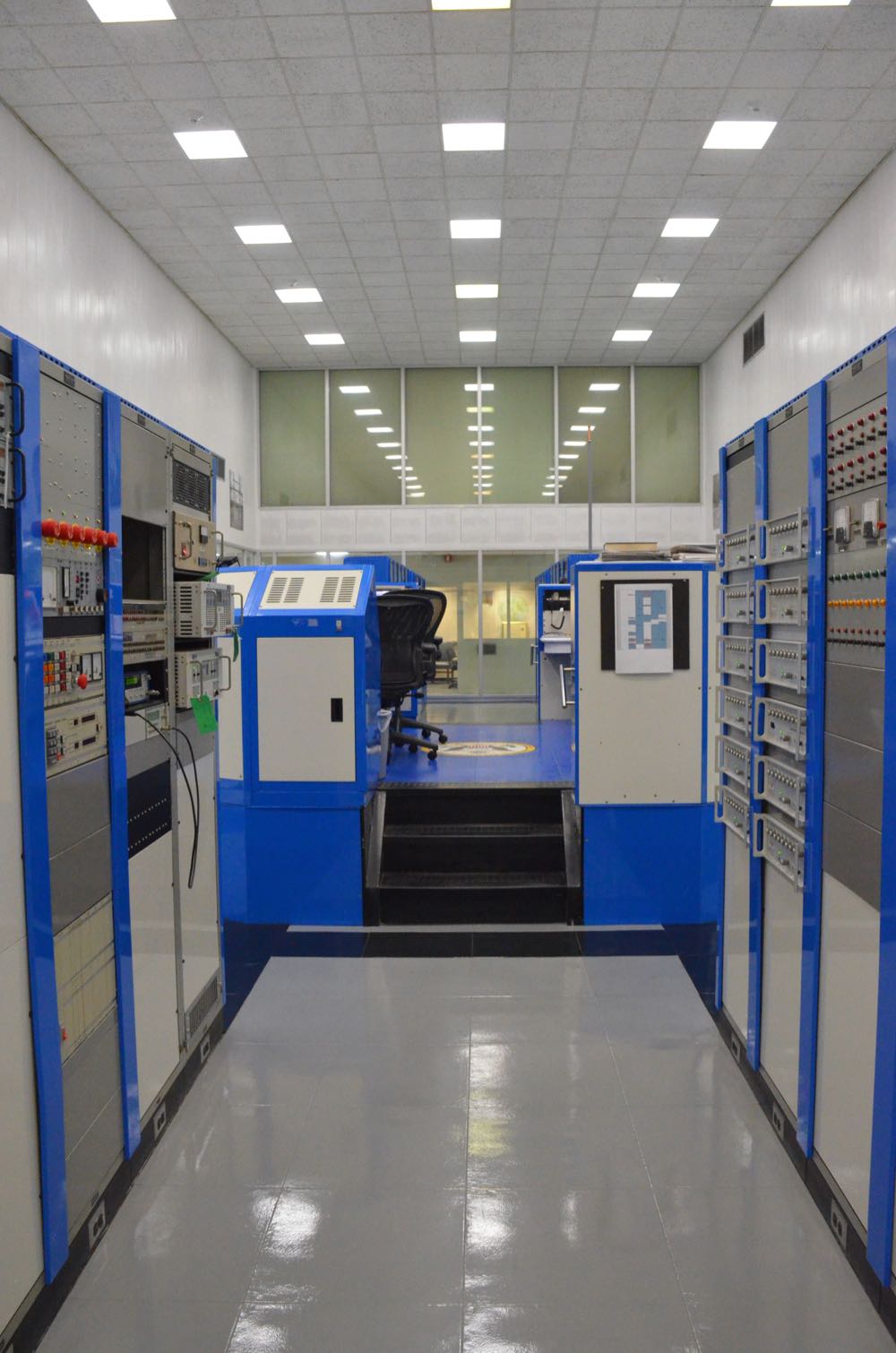
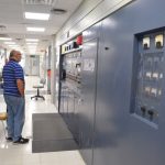
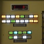
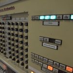
View into the control room from the mezzanine.

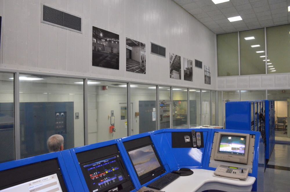
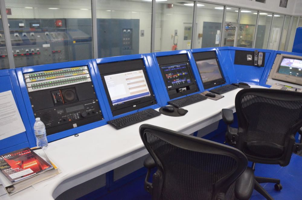
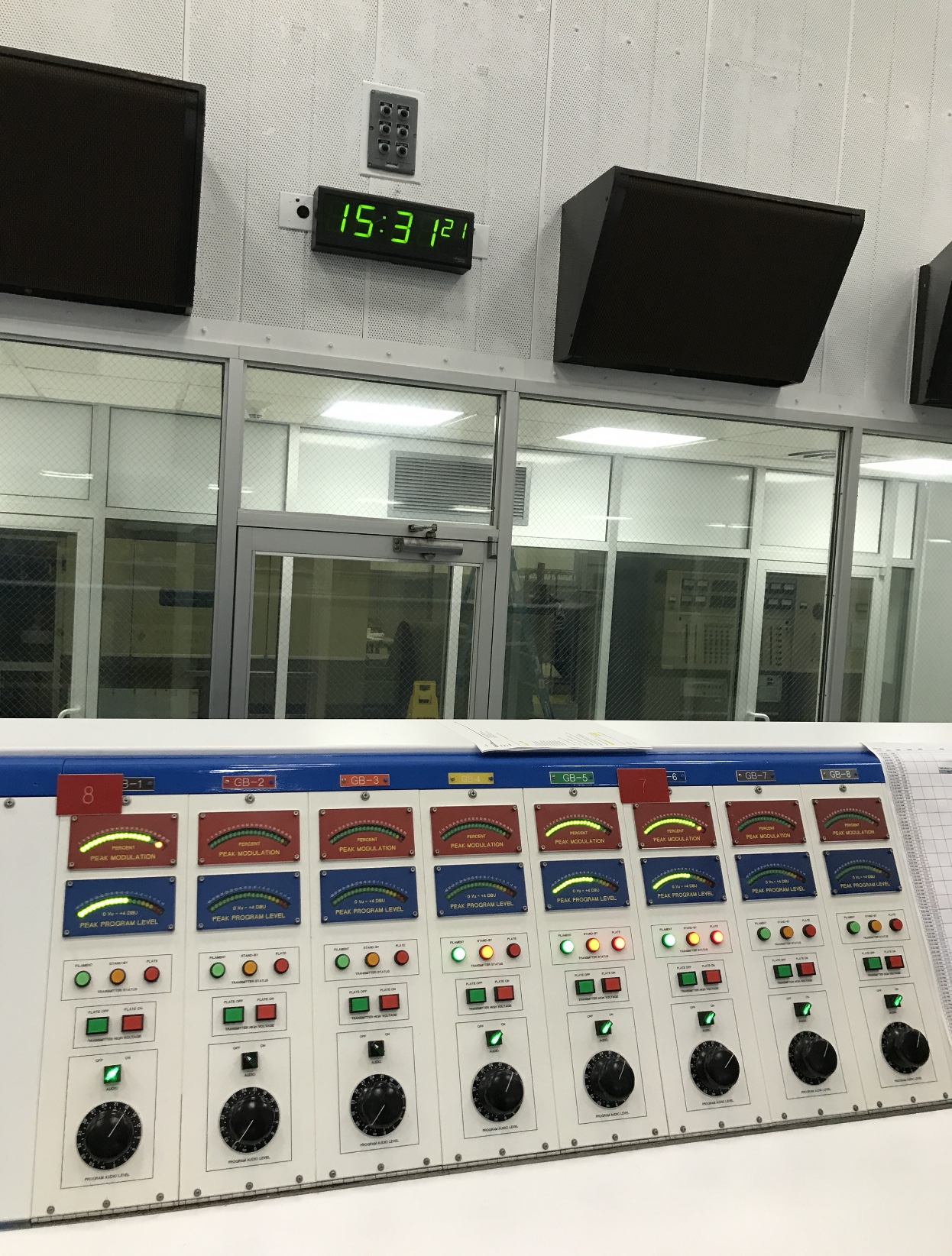
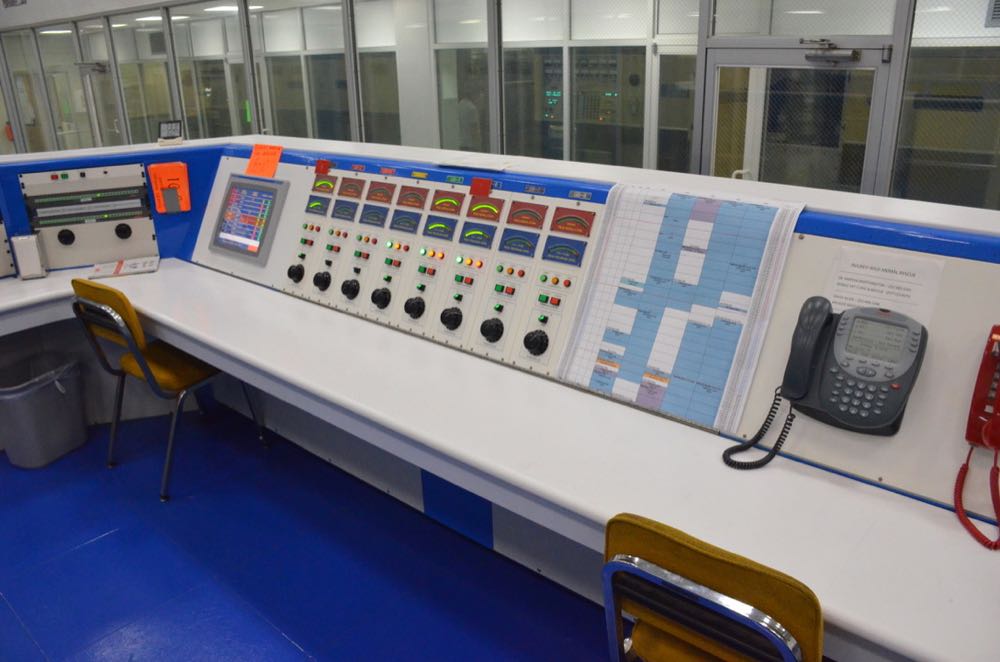
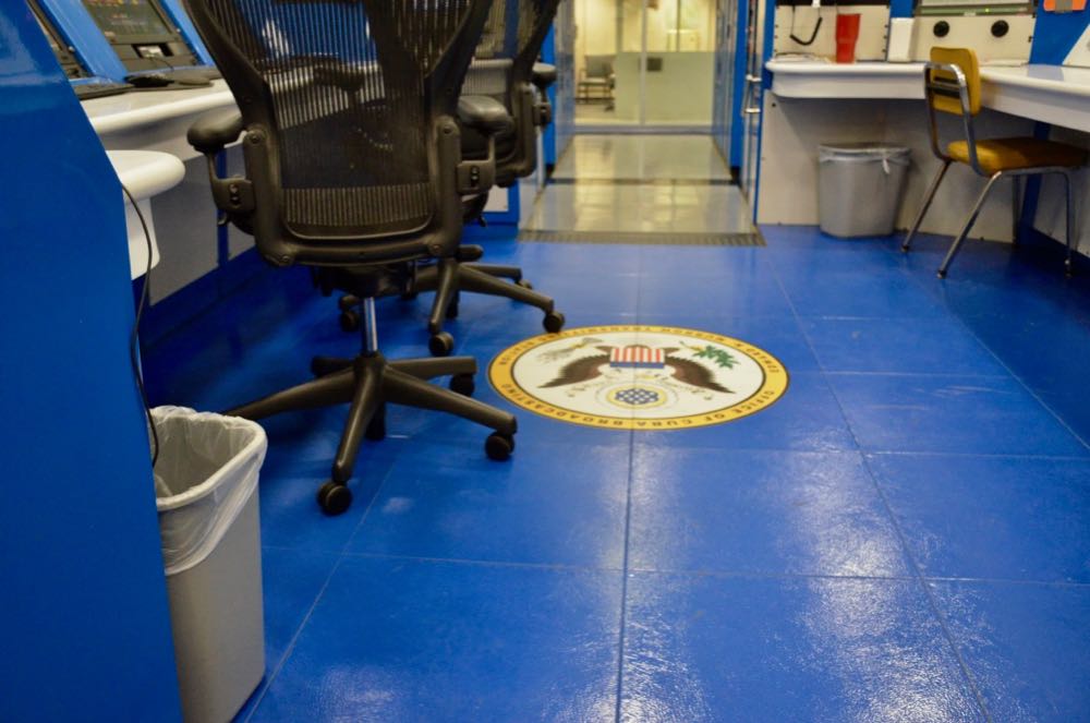
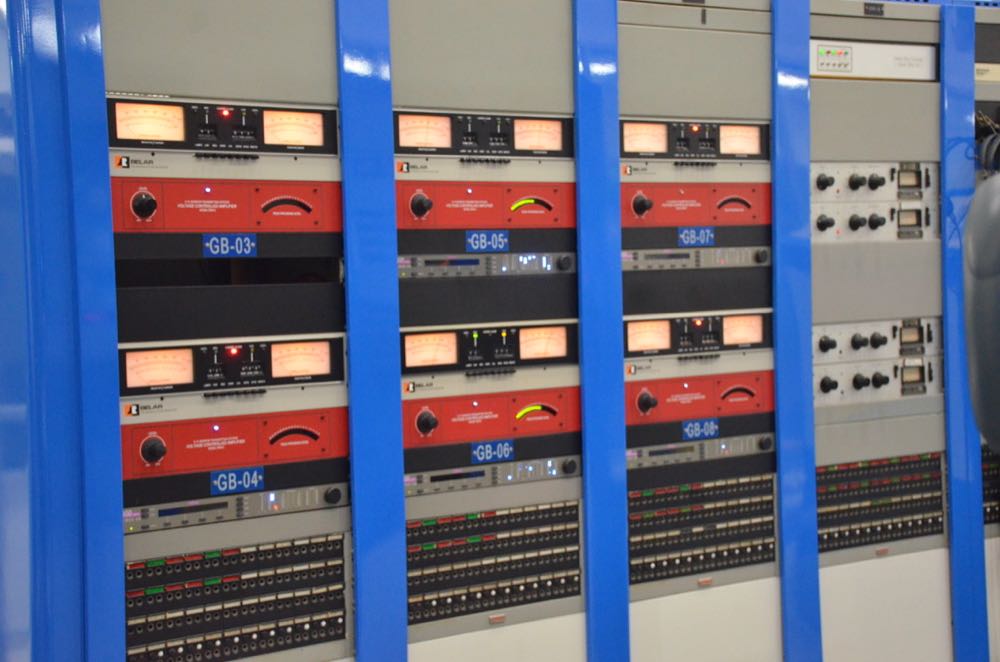
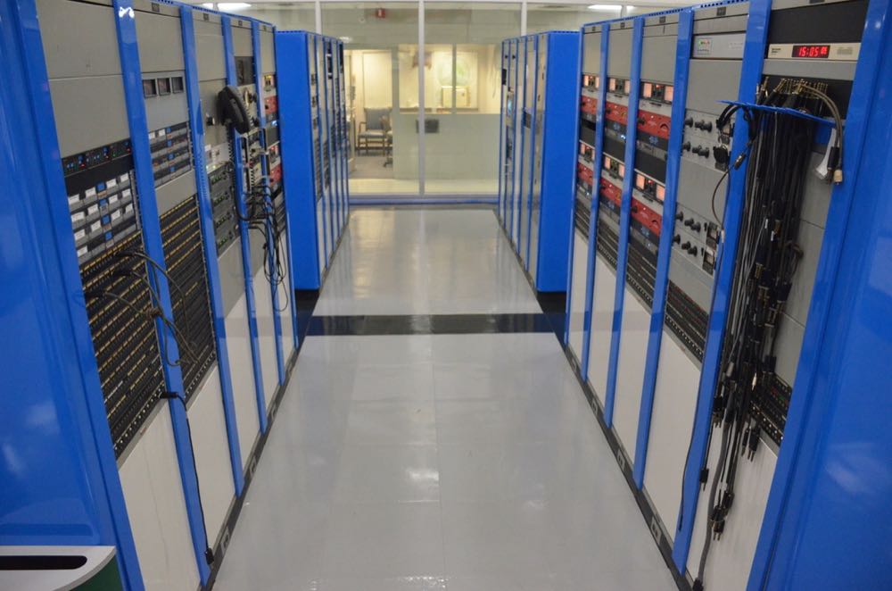
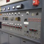
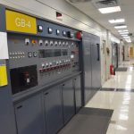
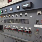
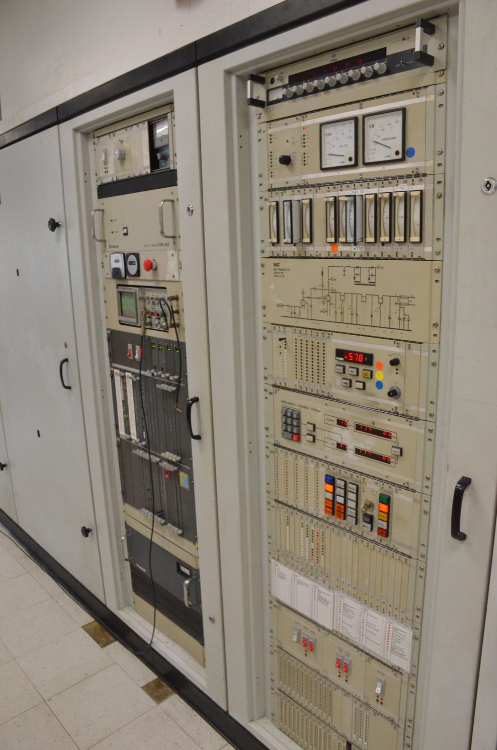
Control room


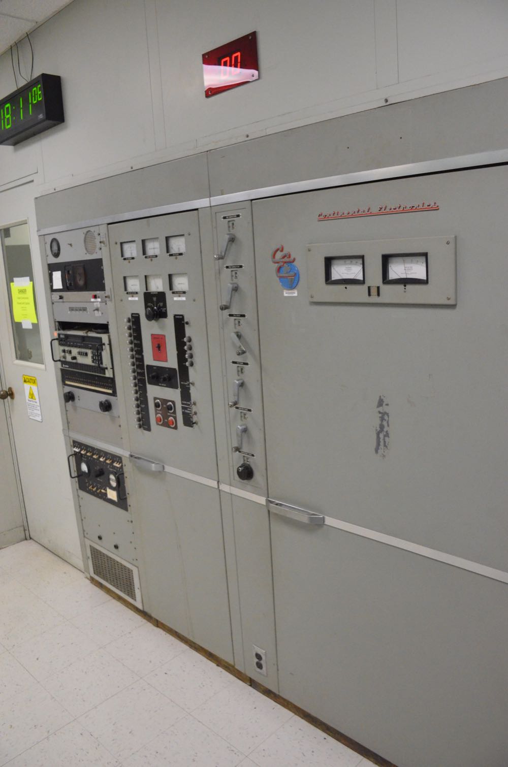
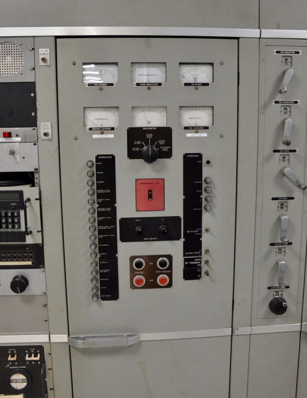
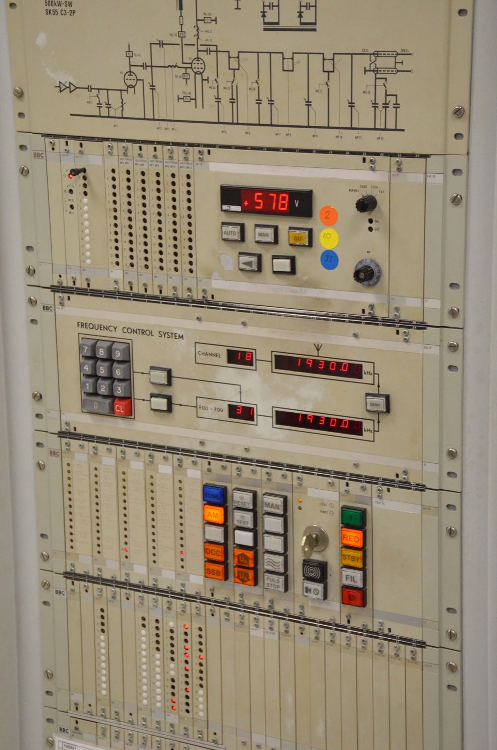
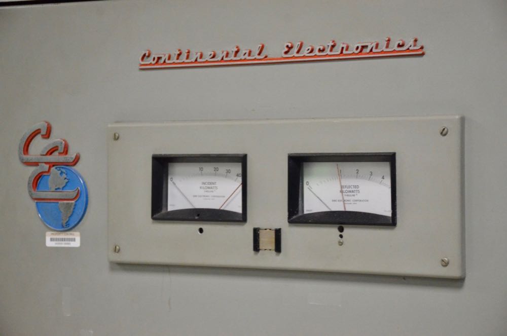
Transmitters


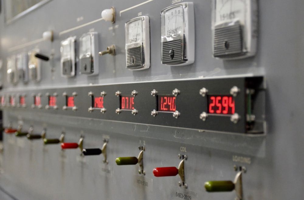
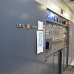
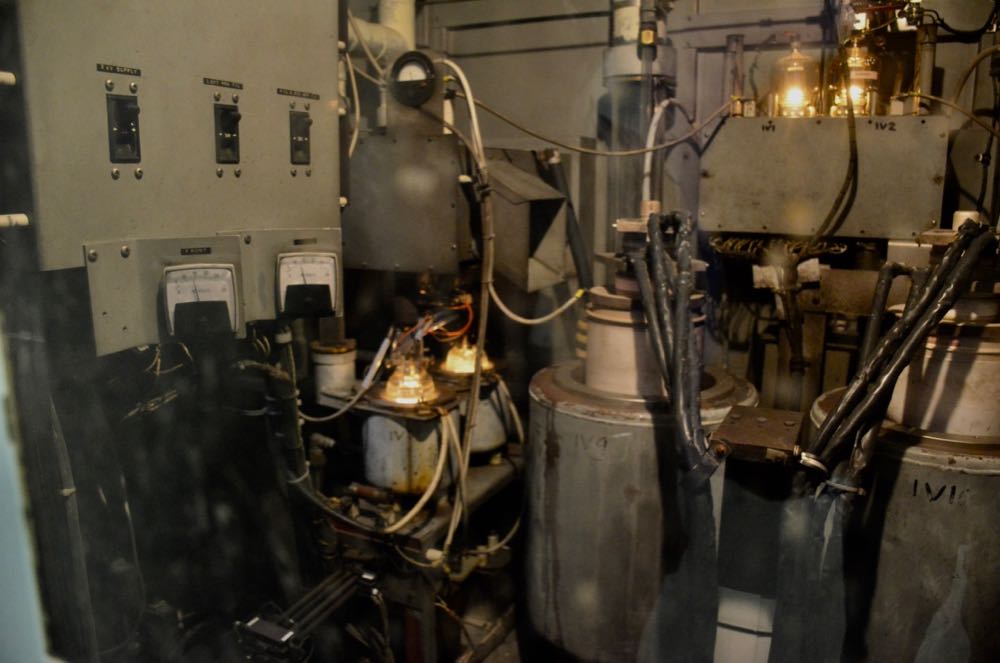
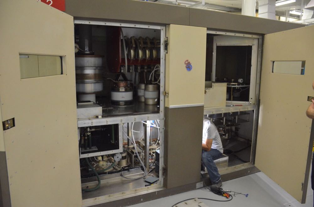
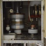
Tubes glowing in the active GE transmitter!

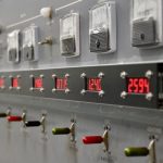
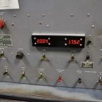
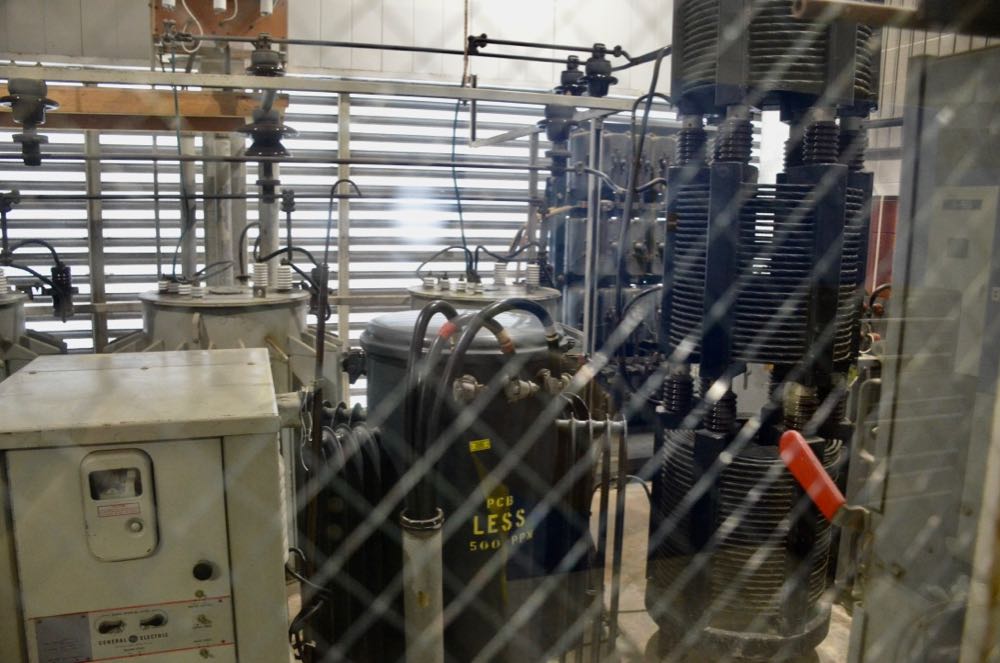
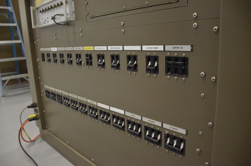
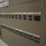
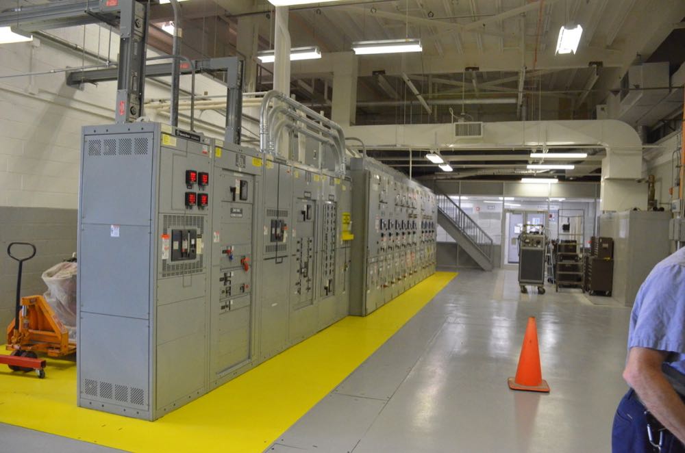
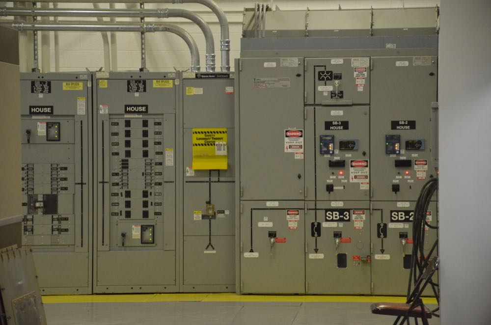
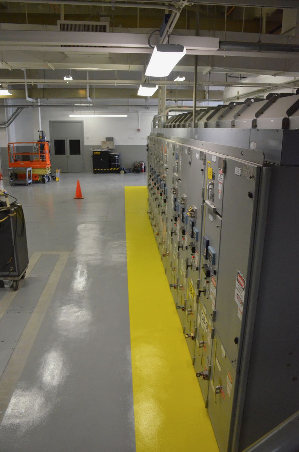
Very high voltage in this power room for the GE transmitters.

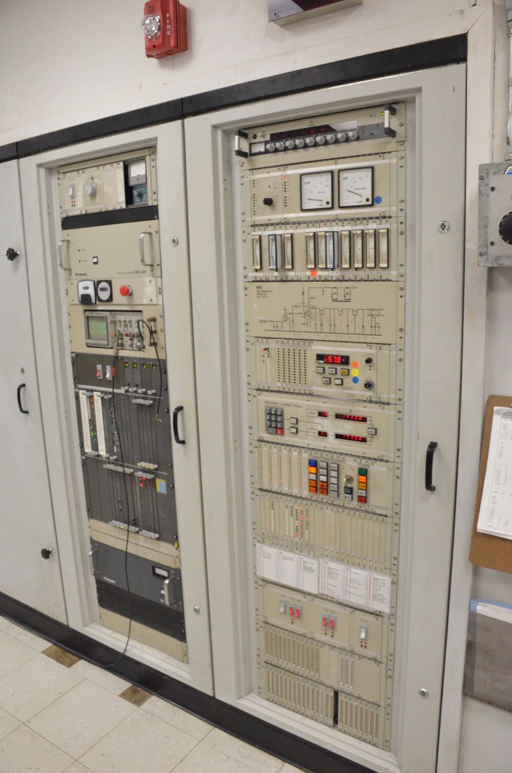
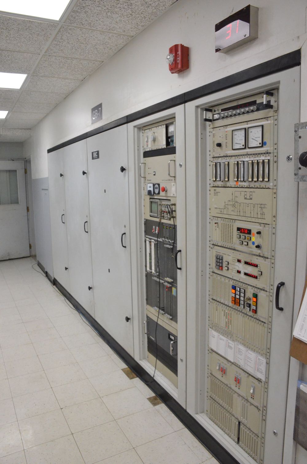
Installing new transmitters

Macon and his team are in the process of installing modern transmitters sent from other IBB sites. As you might imagine, this is a tedious process, and requires highly-skilled technicians.


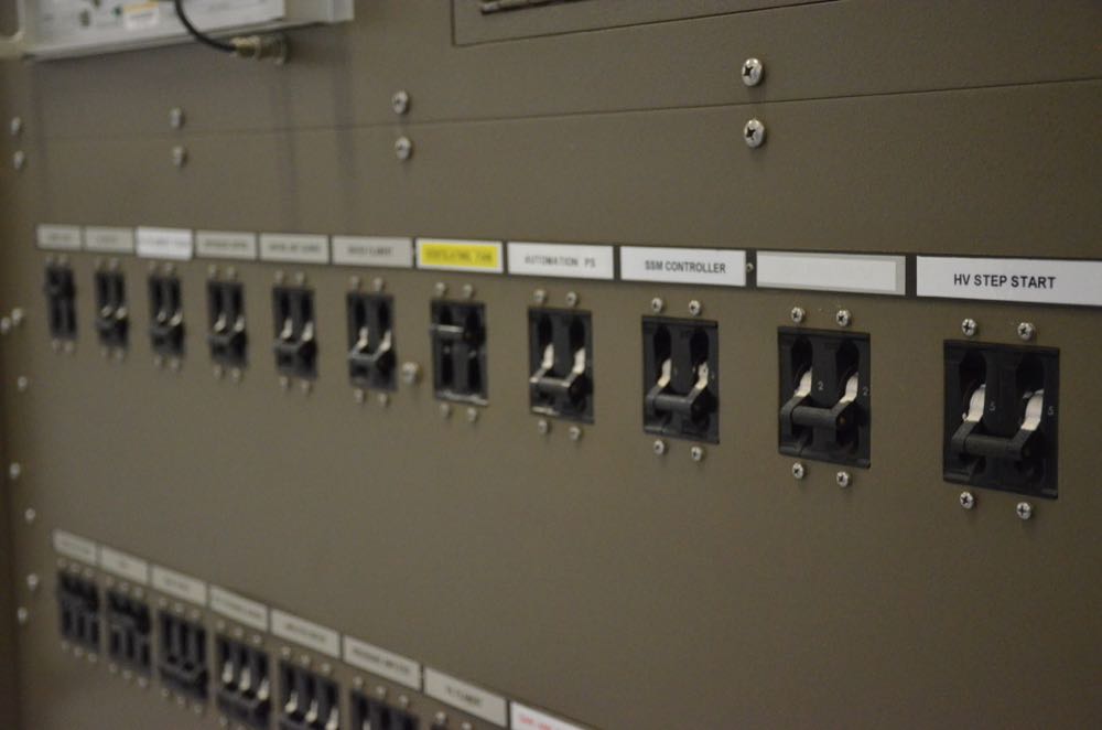
Power

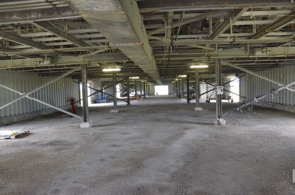
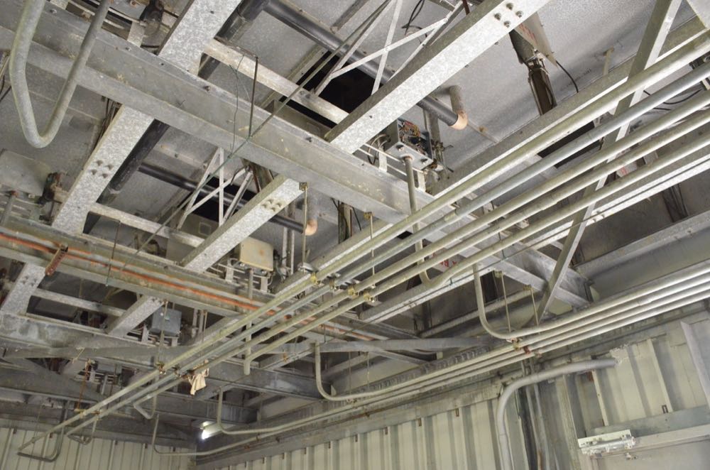
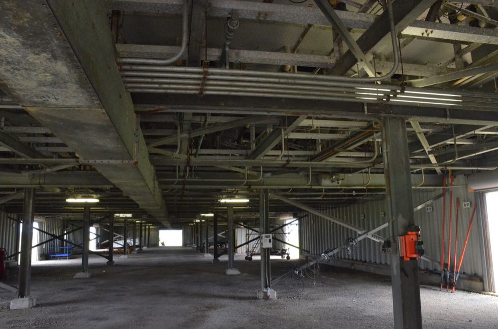
Antenna switching bay and feed lines

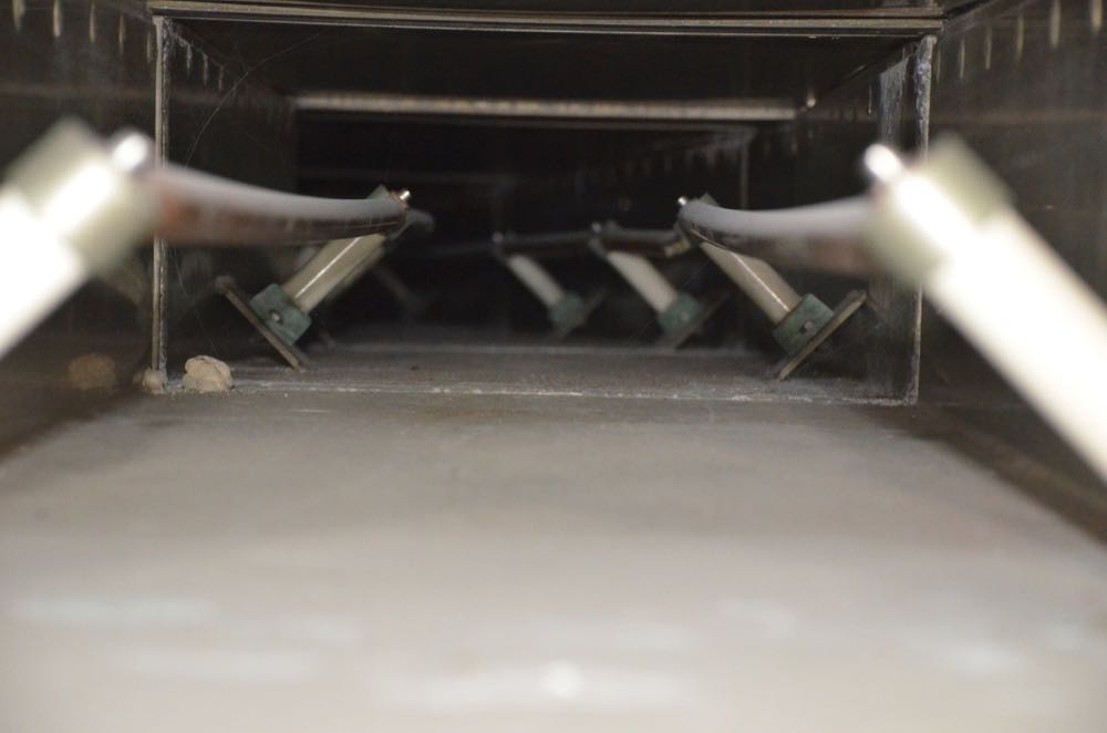
In this photo, we’re looking straight down a 50 kW feed line in conduit which leads to the switching bay. Normally, this would not be accessible, but this line is being built for a new transmitter.

The antenna switching bay is truly massive…

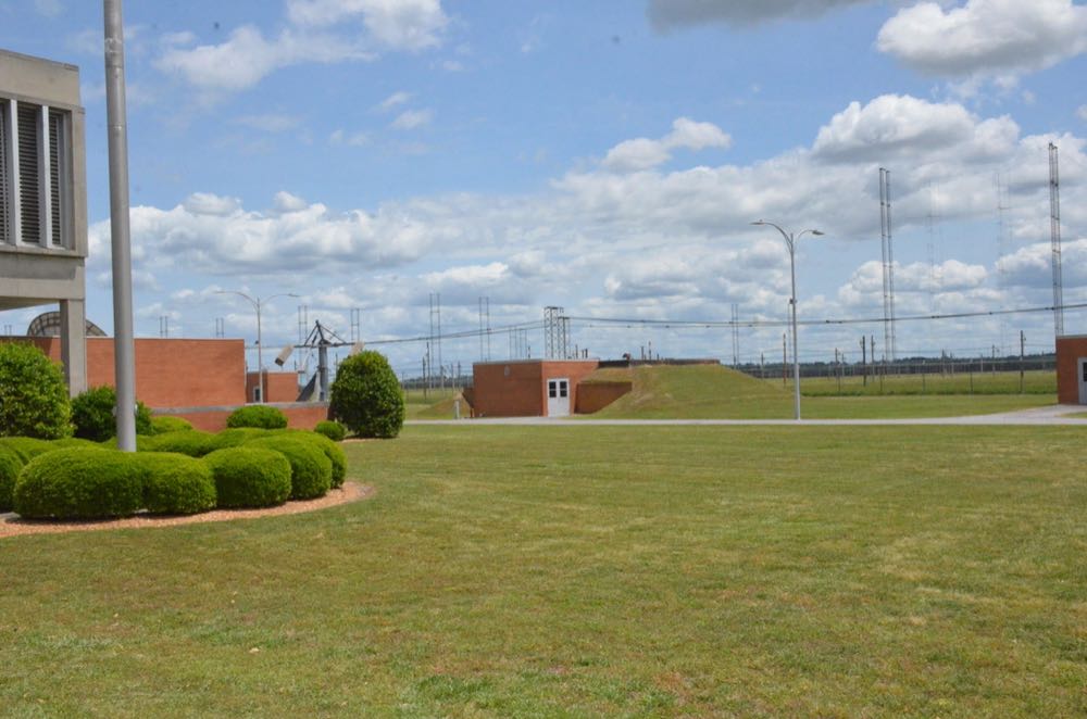
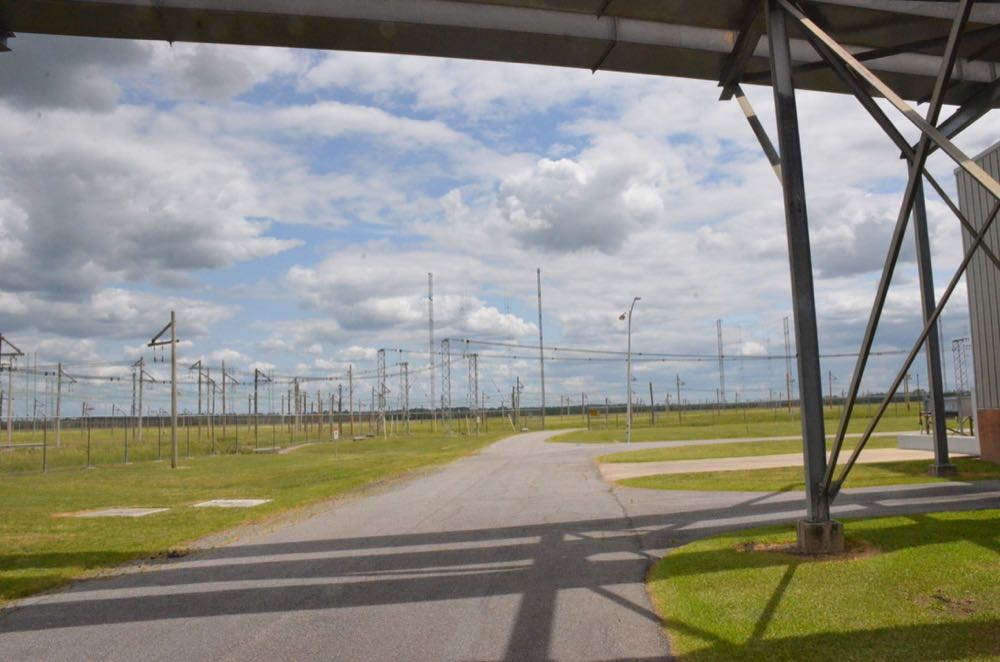
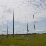
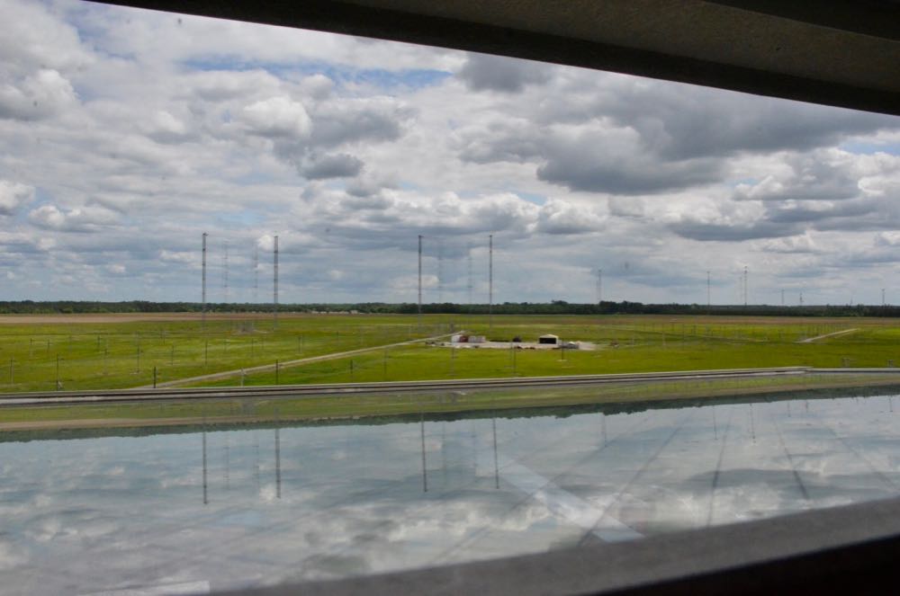
Antenna farm

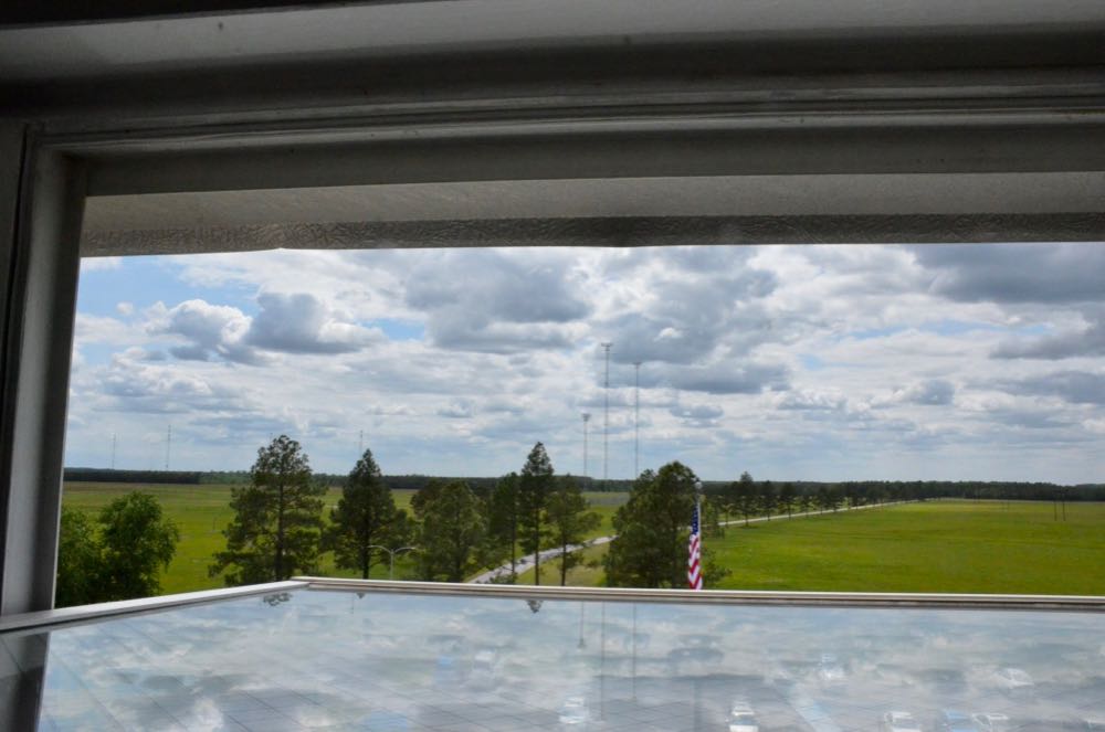
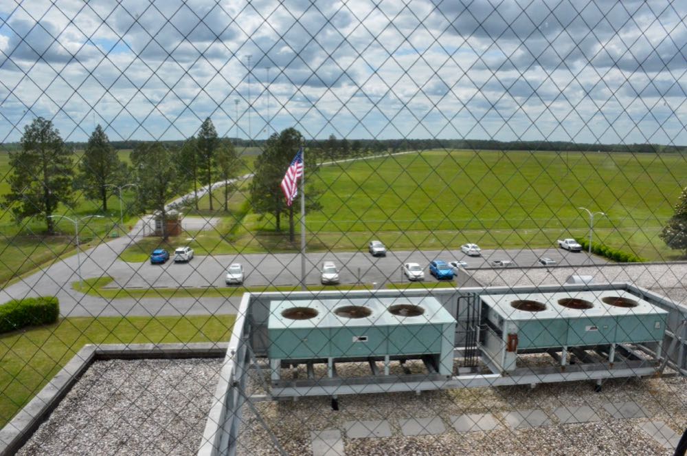
View from the observation tower

Wow, what a tour…

John and I enjoyed our in-depth tour of the Edward R. Murrow Transmitting Station! The staff, as always, were incredibly welcoming and accommodating.

I believe this was my fourth tour; nonetheless, I still discovered new things, and it’s no wonder. The staff of the station are constantly upgrading, updating, and tweaking the performance of their equipment. This is the reason their signals are always full-fidelity and crystal-clear on the air.

I’m simply amazed by all they accomplish.  Keeping this station running is certainly a labor of love.

Of course, this won’t be my last visit to the station.  I fully intend to return, if not later this year, at least next, to check out the new transmitters in operation.  Stay tuned! To this active VOA station.

Click here to read an article about my first visit to the Murrow Transmitting Station.


Do you enjoy the SWLing Post?

Please consider supporting us via Patreon or our Coffee Fund!

Your support makes articles like this one possible. Thank you!