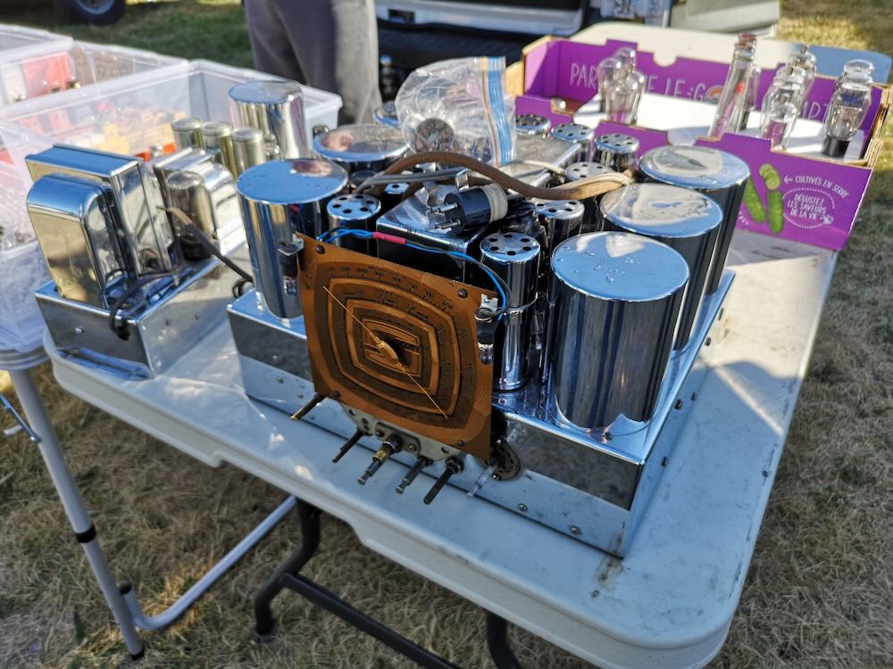
Radio Waves: Michael Pack Resigns, FCC Enforcement Advisory, Upcoming ISS SSTV, and Prowling TV Detector Vans

Radio Waves:  Stories Making Waves in the World of Radio

Because I keep my ear to the waves, as well as receive many tips from others who do the same, I find myself privy to radio-related stories that might interest SWLing Post readers.  To that end: Welcome to the SWLing Post’s Radio Waves, a collection of links to interesting stories making waves in the world of radio. Enjoy!

Many thanks to SWLing Post contributors Eric McFadden, Ronald Kenyon,  for the following tips:


Defined By Scandal At Voice of America, CEO Resigns At Biden’s Request (NPR)

Michael Pack resigned Wednesday as the CEO of the federal agency over the Voice of America and other federally funded international broadcasters after a turbulent seven-month tenure. He leaves the U.S. Agency for Global Media with a Trumpian legacy of ideological strife, lawsuits and scandal, his departure effective just two hours after the swearing-in of President Biden, who requested him to leave.

Biden has named senior VOA news executive Kelu Chao as acting CEO.

Pack came to lead the U.S. Agency for Global Media with the support of former President Donald Trump; his appointment was delayed more than two years in the U.S. Senate by lawmakers who feared he was too ideological and also who questioned his finances. The soft-spoken conservative documentary maker proved to be an ideological warrior in the mold of his patron, taking to one conservative news outlet after another to denounce his own staff, all in the name of fairness.

In his resignation letter, Pack said he was “solely focused upon reorienting the agency toward its missions.” And he attacked the request for his resignation as “a partisan act,” saying the leadership of the agency and its networks “is meant to be non-partisan, untethered to alternations in the political regime.”

He added, “I had no political agenda coming into USAGM, and I still do not have one.”

NPR conducted scores of interviews over the controversies Pack’s actions engendered. And few at the agency or its broadcasters agreed with Pack’s characterization of his mission or performance, instead characterizing him as seeking political control over their coverage. Just last week, a VOA reporter’s insistent questions to then-Secretary of State Mike Pompeo and VOA Director Robert R. Reilly over the siege on Congress after a public event led to her demotion and an investigation.

Pack routinely accused journalists of anti-Trump bias, sought to fire top executives as part of a “deep state,” ominously accused the networks of being receptive to foreign spies and denied requests for visa extensions from his own staffers who are foreign nationals.[]

FCC Issues Enforcement Advisory: Radio Users Reminded Not to Use Radios in Crimes (ARRL News)

The FCC has released an Enforcement Advisory for licensees and operators across radio services.

[Complete text of FCC Enforcement Advisory follows.]

FCC ENFORCEMENT ADVISORY

DA 21-73

Released: January 17, 2021

WARNING: AMATEUR AND PERSONAL RADIO SERVICES LICENSEES AND OPERATORS MAY NOT USE RADIO EQUIPMENT TO COMMIT OR FACILITATE CRIMINAL ACTS

The Enforcement Bureau (Bureau) of the Federal Communications Commission issues this Enforcement Advisory to remind licensees in the Amateur Radio Service, as well as licensees and operators in the Personal Radio Services, that the Commission prohibits the use of radios in those services to commit or facilitate criminal acts.

The Bureau has become aware of discussions on social media platforms suggesting that certain radio services regulated by the Commission may be an alternative to social media platforms for groups to communicate and coordinate future activities. The Bureau recognizes that these services can be used for a wide range of permitted purposes, including speech that is protected under the First Amendment of the U.S. Constitution. Amateur and Personal Radio Services, however, may not be used to commit or facilitate crimes.

Specifically, the Bureau reminds amateur licensees that they are prohibited from transmitting “communications intended to facilitate a criminal act” or “messages encoded for the purpose of obscuring their meaning.” 47 CFR § 97.113(a)(4).

Likewise, individuals operating radios in the Personal Radio Services, a category that includes Citizens Band radios, Family Radio Service walkie-talkies, and General Mobile Radio Service, are prohibited from using those radios “in connection with any activity which is against Federal, State or local law.” 47 CFR § 95.333(a).

Individuals using radios in the Amateur or Personal Radio Services in this manner may be subject to severe penalties, including significant fines, seizure of the offending equipment, and, in some cases, criminal prosecution. 47 U.S.C. §§ 401, 501, 503, 510.

Media inquiries should be directed to 202-418-0500 or [email protected].

To file a complaint with the FCC, visit https://consumercomplaints.fcc.gov or call 1-888-CALL-FCC. To report a crime, contact your local law enforcement office or the FBI.

To request materials in accessible formats for people with disabilities (Braille, large print, electronic files, audio format), send an e-mail to [email protected] or call the Consumer & Governmental Affairs Bureau at (202) 418-0530 (voice), (202) 418-0432 (TTY).

Issued by: Chief, Enforcement Bureau[]

ISS SSTV 145.800 FM Jan 28-29 (Southgate ARC)

Russian cosmonauts on the International Space Station (ISS) are planning to transmit Slow Scan TV images on 145.800 MHz FM using the SSTV mode PD-120

The transmissions are part of the Moscow Aviation Institute SSTV experiment (MAI-75).

Jan 28 – Starts after 12:10 GMT and ends at 17:15 GMT*

Jan 29 – Start about 13:10 GMT and ends at 18:05 GMT*

*Dates and times subject to change.

ARISS SSTV Blog
https://ariss-sstv.blogspot.com/

Useful SSTV info and links
https://amsat-uk.org/beginners/iss-sstv/

TV Detector Vans Once Prowled The Streets Of England (Hackaday)

The United Kingdom is somewhat unique in the world for requiring those households which view broadcast television to purchase a licence for the privilege.

Initially coming into being with the Wireless Telegraphy Act in 1923, the licence was required for anyone receiving broadcast radio, before being expanded to cover television in 1946. The funds generated from this endeavour are used as the primary funding for the British Broadcasting Corporation.

A typical TV licence invoice. Separate licences for black and white and color sets still exist, with 6000 B&W licences issued in 2019.

Of course, it’s all well and good to require a licence, but without some manner of enforcement, the measure doesn’t have any teeth. Among other measures, the BBC have gone as far as employing special vans to hunt down illegally operating televisions and protect its precious income.

THE VAN IS COMING FOR YOU

To ensure a regular income, the BBC runs enforcement operations under the TV Licencing trade name, the entity which is responsible for administering the system. Records are kept of licences and their expiry dates, and investigations are made into households suspected of owning a television who have not paid the requisite fees. To encourage compliance, TV Licencing regularly sends sternly worded letters to those who have let their licence lapse or have not purchased one. In the event this fails, they may arrange a visit from enforcement officers. These officers aren’t empowered to forcibly enter homes, so in the event a homeowner declines to cooperate with an investigation, TV Licencing will apply for a search warrant. This may be on the basis of evidence such as a satellite dish or antenna spotted on the roof of a dwelling, or a remote spied on a couch cushion through a window.[]


Do you enjoy the SWLing Post?

Please consider supporting us via Patreon or our Coffee Fund!

Your support makes articles like this one possible. Thank you!

Spread the radio love

Don discovers a treasure trove of digitized vintage radio books and magazines

Many thanks to SWLing Post contributor, Don (W7SSB), who writes:

I thought these links might be of interest to your readers:

https://www.qsl.net/va3iul/Files/Old_Radio_Frequency_Books.htm

https://www.qsl.net/va3iul/

Brilliant! Thanks for the tip, Don!

Of course, another deep treasure trove is the World Radio History website.

Spread the radio love

FTIOM & UBMP, January 24-30


From the Isle of Music, January 24-30:

This week, we enjoy several vocal quartets including Los Modernistas, Tema IV, Gema 4, Los Meme and Los Brito.
The broadcasts take place:
1. For Eastern Europe but audible well beyond the target area in most of the Eastern Hemisphere (including parts of East Asia and Oceania) with 100Kw, Sunday 1500-1600 UTC on SpaceLine, 9400 KHz, from Sofia, Bulgaria (1800-1900 MSK)
2. For the Americas and parts of Europe, Tuesday 0100-0200 on WBCQ, 7490 kHz from Monticello, ME, USA (Monday 8-9PM EST in the US).
3 & 4. For Europe and sometimes beyond, Tuesday 1900-2000 UTC and Saturday 1300-1400 UTC on Channel 292, 6070 kHz from Rohrbach, Germany.
Our Facebook page is https://www.facebook.com/fromtheisleofmusic/
Our V-Kontakte page is https://vk.com/fromtheisleofmusic
Our Patreon page is https://www.patreon.com/tilford

Uncle Bill’s Melting Pot, January 24-30:
In episode 201, we enjoy traditional and modern music from New Zealand.
The transmissions take place:
1.Sunday 2300-0000 (6:00PM -7:00PM EST) on WBCQ The Planet 7490 kHz from the US to the Americas and parts of Europe
2. Tuesday 2000-2100 UTC on Channel 292, 6070 kHz from Rohrbach, Germany for Europe.
3. Saturday 0800-0900 UTC on Channel 292, 9670 kHz from Rohrbach, Germany for Europe with a directional booster aimed eastward.
Our Facebook page is https://www.facebook.com/UncleBillsMeltingPot/
Our V-Kontakte page is https://vk.com/fromtheisleofmusic
Our Patreon page is https://www.patreon.com/tilford

Spread the radio love

The new Sangean SG-108 portable HD radio

Many thanks for SWLing Post contributor, Zack Schindler, who shares the following:

Sangean released a new MW/FM/HDRadio this year, the SG-108: https://www.sangean.com/products/product.asp?mid=261&cid=3

It seems to be identical to the HDR-14 except for the color https://www.sangean.com/products/product.asp?mid=230&cid=3.

I wonder if the receiver is any better than the HDR-14? I have an HDR-14 and am amazed by its performance every time I use it.

Thanks for the tip, Zack! I, too, love the HDR-14. I also love the fact the SG-108 still uses AA batteries as well.

Spread the radio love

Studio recording of the KMTS “Boot Up!” broadcast

Many thanks to the folks at KMTS who share the following:

A studio version of the KMTS Boot Up Special of 17.1.2021 on 7780 kHz at 0100 UTC. This transmission consisted of Country and Western sounds, engineer test signals, rare re-media mixes of cult radio favourites, strange tones, and vox.

Rebroadcasts: 7 pm eastern time Sunday January 17th 2021 and Sunday January 24th 2021 (0:00 UTC Monday 1/18 and 1/25 on 9395 kHz.

Click here to listen via SoundCloud.

Spread the radio love

The EMTX: How to build an 8 component 40/30 meter QRP emergency transmitter

Many thanks to SWLing Post contributor, Kostas (SV3ORA), for sharing the following guest post which originally appeared on his radio website:


Emergency transmitter: An 8-component, high-power 40m/30m transmitter to get you quickly on the air

by Kostas (SV3ORA)

Introduction

QRP is all about doing more with less. This is more than true, with the construction of this cheap, simplistic transmitter presented here. It is designed primarily as an emergency transmitter (EMTX) that can be built or serviced in the field or at any home. However, it can be used as a HAM radio transmitter as well. Do not judge by its low components count though. This transmitter is powerful, more powerful than anything the QRPers would dream of. It is just remarkable how 8 components can lead in so much output power, that lets you communicate with a big part of the world, when propagation conditions are right. It is very difficult for a circuit to match that kind of simplicity in balance with such performance.

Following my detailed instructions, the EMTX can be reproduced easily, within hours. The result is always success, this is one of the circuits that are not critical at all and a successfully working transmitter can be reproduced every time. I have built this transmitter several times, using similar components (even toroids) and it always worked. The transmitter meets the next expectations:

1. Output power (including harmonics): A few mW up to 15W (depended on transistor, crystals and voltage/current used) at 50 ohm.
2. It can drive any antenna directly, 50 ohm or higher impedance, without external tuners.
3. Bands of operation: Currently 40m, 30m
4. Mode: CW, Feld-Hell (with external switching circuit), TAP code and any other ON/OFF keying mode. AM modulation has been easily applied too.
5. Options like reverse polarity protection diode (useful in the field when testing different unknown polarities PSUs) and current meter (for easier tuning) are available.

The challenge

The purpose of this transmitter is to be used primarily as an emergency transmitter. This poses several challenges that influence the design of the transmitter:

1. It must be able to be built or serviced easily in the field or at any home, with components that could be salvaged from near by electronics sources or a small electronics junk box. This means that components count should be kept very low and they must not be rare to find but commonly available parts. As a side effect cost would also be kept small, if one is to buy any component. Also, the active components must be interchangable with many other devices without the need for the design or the rest of the circuit components to be changed.

2. It must be able to operate from a very wide range of DC voltage sources and at relatively low current, so that common house power supplies could be used to supply power to it. Such devices include linear or switched mode power supplies from laptop computers, routers, printers, cell phone chargers, Christmas lights or any other device one might have available.

3. It must be capable of transmitting a powerful signal, so that communication is ensured. An emergency transmitter that is capable of a few mW of output power, might be heard locally (still useful, but there are handheld devices for that already) but isn’t going to be of much usage if it can’t be heard really far away.

4. It must be capable of loading any antenna without external equipment required. In an emergency situation, you just don’t have the luxury of building nice antennas or carrying coaxial cables and tuners. There may be even extreme cases where you can’t even carry a wire antenna and you depend on salvaging wire from sources in the field to put out a quick and dirty random wire antenna.

5. Adjustments of the transmitter should be kept minimum without the help of any external equipment and there must be indication of the correct operation of the transmitter or the antenna in the field.

Components selection

The transistor:
This transmitter has been designed so that it can operate with any NPN BJT in place. This includes small signal RF and audio transistors and high power RF transistors like the ones used on HF amplifiers and CB radios. Despite 2sc2078 is shown in the schematic, just try any NPN BJT in place and adjust the variable capacitor accordingly. When you are in the field, you do not have the luxury of finding special types of transistors. The transmitter must operate with any transistor in hand, or salvaged from near-by equipment. Of course the power capability of the transistor (as well as the crystal current handling) will determine the maximum VCC and current that can be applied to it and hence the maximum output power of the transmitter. Some of the most powerful transistors I have used, come out of old CB radios, such as the 2sc2078, 2sc2166, 2sc1971, 2sc3133, 2sc1969 and 2sc2312. There are many others. As an example, the 2sc2078 with a 20v laptop PSU, gave 10-12W of maximum output power into a 50 ohms load.

Schematic of the 8 components EMTX for the 40m/30m bands. Components with gray color are optional.

The crystal:
This is the most uncommon part of the transmitter. You have to find the crystal for the frequency that you want to operate on. Crystals within the 40m or 30m CW segments are not that common. Further more if you operate the transmitter at high powers and currents, you will notice crystal heating and chirp on the frequency of the transmitter. The current handling capability of your crystal die inside the crystal case, will determine the chirp and the amount of crystal heating. You can still work stations with a chirpy transmitter provided that the chirp is not that high, so that it can pass through the CW filters of the receivers. However, if a small chirp annoys you or if this chirp is too much, then you have to use these vintage bigger size crystals (e.g. FT-243), that can handle more current through them. But these are even more uncommon today.

The approach I have used in my prototype, was to connect more than one HC-49U crystals of the same frequency in parallel, so that the current is shared among them. This reduced the chirp at almost unnoticeable levels, even at high output power, just if I was using a single FT-243 crystal, or even better in some cases. Again, this is optional, but if you want to minimize chirp (and crystal heating) without searching for rare vintage crystals, this is the way to go.

A bit of warning. If you notice a very high chirp when plugging in a crystal to the EMTX, you should consider this crystal as inappropriate for this transmitter, as it cannot handle the current required. If you continue to use this inappropriate crystal, you could easily crack it inside and set it useless. Don’t use these tiny HC-49S crystals, they won’t work.

The current meter:
A 1Amp (or even larger) current meter can be used to monitor the current drawn by the transmitter during key down. The recommended current operating point is anywhere between 450mA to 1A, depended on the output power (and harmonics) level you want to achieve. The current point is set by the variable capacitor. I would avoid setting the current to more than 1Amp, although it can be done. The use of the current meter is optional, but along with the incandescent bulb, will give you a nice indication of the correct tuning of the transmitter, so that you do not need to have an external RF power meter connected to the transmitter output. If you do have, then you can remove the current meter. If you don’t have a 1Amp analogue meter available, but a smaller one, you can parallel a low value power resistor across the meter. In my case, I only had a 100uA meter and I paralleled a 0.15 ohms 5W resistor across it to scale down 1Amp to 100uA, The resistor value depends on the internal meter resistance so you have to calculate this for your specific meter. When the 2sc2078 is used at 20V, 500mA in the current meter indicates around 5W of output power, 600mA indicates around 6W, 700mA 7W, 800mA 8W, 900mA 9W and 1A around 10W. So the current meter can be used as sort of power meter without the need to do any scaling on it.

The incandescent bulb:
A current meter alone, without the use of the incandescent bulb, will not give you the right indication of the operation of the transmitter. In some cases, the transmitter might be drawing current without actually generating much, or even any RF. When you are in the field you do not want to carry extra monitoring equipment with you. The incandescent bulb will light on when the transmitter oscillates. It monitors the actual RF signal, so it’s brightness changes according to the amount of RF power the transmitter produces. Along with the current meter reading, this is just what you need to know in order to set the variable capacitor properly. Note that the bulb will not lit at very low signal levels. The one used in the prototype starts to glow up from a bit less than 1W. Miniature incandescent bulbs may not be that easy to find nowadays. However, there is a good source of these, that almost anyone has in their houses. This source is the old Christmas lights. You do save old Christmas lights, don’t you? The incandescent bulb indicator as well as it’s single turn winding on the transformer, are optional components. If you have an RF power meter connected to the transmitter, you can remove these.

The diode:
The protection diode is an optional component to the circuit. If you are in the field, correct polarity of a power supply may not be obvious. Without a multimeter it might me difficult to determine the correct polarity of the PSU. A power diode (I used a 6A one) will protect the transistor from blowing up in the event that reverse polarity is connected to the circuit.

The Cx and Cy:
The Cx and especially the Cy capacitors need to be of good quality. The Cy will get hot on high output power if it isn’t. In the tests, I have used homemade gimmick capacitor and even double-sided PCB as a capacitor for Cy and they all got hot at high power. Silver mica capacitors run much cooler and they do make a small difference in the output power, so I suggest to this type. Cy must be able to handle quite a lot of voltage, so silver mica type is ideal.

The variable capacitor:
The variable capacitor can be air variable or ceramic, although I prefer air variables in tis application. In any case it must be able to handle a high voltage just as the Cy.

The key:
The key directly shorts the transistor emitter to the ground, therefore it is a part of the active circuit. For this reason, I suggest the key leads to be kept as short as possible. The key must be able to handle the voltage (20v) and current (up to 1A) on its contacts, which is usually not a big deal.

Transformer construction

The construction of the transformer is shown below step by step. Note that if you decide that you don’t need to drive higher impedance loads but just 50 ohm ones (eg. antenna tuners or 50 ohm matched antennas), you just need to wind 2t in the secondary and not 14t. You also don’t need any taps of course.

Step 1:

Take a piece of 32mm external diameter PVC pipe from a plumber’s shop. Alternatively, a suitable diameter pills box can be used, or any other suitable diameter plastic tube.

Step 2:

Cut a 4cm piece out of this tube. 4cm is the minimum length required.

Below a 4cm PVC tube has been cut in size.

Step 3:

Wind 16 turns of 1mm diameter enameled wire onto the PVC pipe and secure the winding in place as shown in the picture below. Notice the winding direction of the wire. This is the primary of the transformer, the one that is connected to the two capacitors. Notice that this winding is wound a bit offset to the right of the pipe.

Step 4:

Wrap the winding with 3 turns of PTFE tape. It can be bought at any plumber’s shop, just like the PVC pipe. The PTFE tape will help in keeping the second layer turns in place and it will provide extra insulation.

Step 5:

Wind 2 turns of 1mm diameter enameled wire on top of the primary winding and secure the winding in place as shown in the picture below. Notice the winding direction of the wire, as well as it’s position relative to the primary winding. This is the feedback of the transformer, the one that is connected to the collector of the transistor.

Step 6:

Wind 14 turns of 1mm diameter enameled wire on top of the primary winding, starting from just next to the 2 turns one and secure this winding in place as shown in the picture below. Notice the winding direction of the wire, as well as its position relative to the primary and the 2 turns windings. This is the secondary (output) of the transformer, the one that is connected to the antenna. At this point do not worry about the taps yet.

Notice in the picture below, the way the windings are secured in place onto the pipe. The wire ends are passed through the pipe using small holes and then bent towards the ends of the pipe and once more to the surface of the pipe, where the connections will be made.

Step 7:

Wind 1 turn of 1mm diameter enameled wire onto the pipe and secure the winding in place as shown in the picture below. Notice the winding position relative to the other windings. This 1 turn winding is placed about 1cm away from the other windings. This is the RF pick up winding, the one that is connected to the incandescent bulb.

Step 8:

Use a sharp cutter (knife) and carefully scrap the enamel of all the windings ends. Do not worry if you cannot scrap the enamel at the bottom side of the wire ends (that touches to the pipe). We just want enough copper exposed to make the connection.

Step 9:

Tin the scrapped wire ends, taking care not to overheat them much.

Step 10:

Now it’s time to make the taps on the secondary winding. Use a sharp cutter (knife) and very carefully scrap the enamel of the wire at the tap points (number of turns). Take much care not to scrap the enamel of the previous and the next turn from each tap point. Do not worry if you just scrap the enamel at the top of the wire (external area). We just want enough copper exposed to make the connection.

Make each tap, a bit offset from the near by taps, like shown in the pictures. This will avoid any short circuits (especially at the 4, 5 and 6 taps) and it will allow for easier connections, especially if alligator clips are used to connect to the taps.

Step 11:

Tin all the tap points, taking care not to overheat them.

Step 12:

This step is optional and it depends on how you decide to do the connections to the taps. You may solder wires directly to the tap points, but in my case I wanted to use alligator clips, so I did the next: I took a piece of a component lead and soldered it’s one end to each tap point. Then I bent the component lead to U-shape and cut it accordingly. This created nice and rigid tap points for the alligator clip.

Step 13:

This step is optional and it depends on how you decide to mount the transformer to your enclosure. In my case, I wanted to create three small legs for the mounting. I cut three pieces of aluminum straps and made holes at both their ends. I made three small holes onto the transformer pipe end and mounted the aluminum straps using screws. After mounting them, I shaped the straps to L-shape. Then I used three more screws to mount the transformer to the enclosure.

The completed transformer is shown in the pictures above and below. The 6 connection points at the bottom of the pipe, are the low voltage points, whereas the 2 points at the top of the pipe, are the high voltage points.

If you have built the transformer as described, the bottom connections are as follows (from left to right):

Wire end 1, connected to the incandescent bulb
Wire end 2, connected to the incandescent bulb
Wire end 3, connected to the current meter
Wire end 4, connected to the current meter
Wire end 5, connected to the GND (ground)
Wire end 6, connected to the transistor collector

The top connections are as follows (from left to right):

Wire end 1, connected to the 25pF variable capacitor and the Cy fixed.
Wire end 2, is the 14th secondary tap and it is left unconnected, or tapped to the appropriate impedance antenna.

Videos of the EMTX in operation

I have made two small videos of the EMTX in operation.

The first 13.5MB video (right click to download), shows the operation when the transmitter is set for a bit less than 10W of output power.

The second 3.5MB video (right click to download), shows the operation when the transmitter is set for about 5W of output power.

EMTX chirp analysis

Every self-exited power oscillator (and even many multi-stage designs) exhibits some amount of chirp. Chirp is mainly considered as the sudden change in frequency when the power oscillator is keyed down. Apart from chirp, there is also the longer term frequency stability that may be considered. The chirp in the EMTX is surprisingly low, if it is built properly. Hans Summers, G0UPL has performed a chirp analysis on my EMTX (PDF) and the EMTX built by VK3YE and presented on YouTube. Hans, performed the analysis from the video/audio recordings of both transmitters. I sent him two videos, one with the EMTX set for an output power of 10W and one where it is set for 5W. The chirp at worst case (10W) was about 30Hz and at 5W in the order of 10Hz or so. Being so small, the chirp is almost undetectable by the ear and it surely poses no problems when passing the tone through narrow CW filters. This is an amazing accomplishment from a transmitter so simple and so powerful.

EMTX harmonics measurement

Every unfiltered transmitter will excibit harmonics at it’s output. This means that the output waveform has some distortion in comparison to a pure sinewave. Many of the transmitters I have seen, present a very distorted output waveform and absolutely need a LPF if they are to be connected to an antenna. I can’t say that this is true for the EMTX, because surprizingly, it has low distordion, despite the high output power it can achieve. Although a LPF is always a good idea, it is not that much needed on the EMTX. However you have to use one to comply with the regulations.

The image above, shows the measurements on the output of the EMTX, when it is set closely to 10W at 50 ohms. The main carrier is exactly at 9.9W and all the harmonics are less than 50mW! Also, the harmonics, do not extend into the VHF region.

The image below, shows the measurements on the output of the EMTX, when it is set closely to 5W at 50 ohms. The main carrier is exactly at 5.17W and all the harmonics are less than 9.6mW! Again, the harmonics, do not extend into the VHF region.

These small harmonics levels aren’t going to be heard very far at all, compared to the powerful carrier. This means only one thing. A LPF, although a good practice, is not mandatory in this transmitter. But you should better use one so that you comply with the regulations.

Many HAMs use just a watt meter to measure the output of their homebrew transmitters. This is not the proper way of doing it, because the watt meter is a non-selective meter. It will measure both the fundamental carrier and the harmonics, without being able to distinguish them. So in an unfiltered transmitter, or in a transmitter with a simple (often non measured) LPF, this way will give a totally false reading of the output power of the transmitter at the set frequency.

The proper way of accurately measuring the output power of a transmitter and the harmonics levels, is a spectrum analyzer. The FFT available in many modern oscilloscopes, having a dynamic range of approximately 50-55dB, is adequate for this purpose as well. A 50 ohms dummy load must be connected at the transmitter output and then the high impedance probe of the scope, is connected to the output of the transmitter as well. This was the way that the above measurements have been performed.

WebSDR tests

Here are some test transmissions, to determine how far one can get with such a transmitter. I have to say that there is an antenna tuner between the EMTX and my inefficient short dipole (not cut for 40m and not even matched to the coaxial). However I could still cover a distance of more than 2500Km even on the 5W setting.

A screenshot of the transmitter signal, as received on a WebSDR 2500Km away and when the EMTX is set for an output power of 10W.

Below, is a picture and an audio recording of the transmitter signal, as received on the same WebSDR and when the EMTX is set for an output power of 5W.

Photos

Pictures of the finished transmitter. You don’t have to build it that nice-looking if you don’t care.

EMTX prototype built on a breadboard. Yes it worked just fine onto a piece of wood.


This is a phenomenal project, Kostas. Thank you so much for sharing it with us. I love the simplicity of this design–truly form following function. With a little patience, anyone could build this transmitter.

Check out this project and numerous others on Kostas’ excellent website.

Spread the radio love