If you’ve been reading the SWLing Post for long, you’ll know that I’m a huge fan of the annual World Radio TV Handbook (WRTH). If you’re a fan of WRTH as well, I’ve got some good news and some…well…less than good news.
Good News: WRTH 2022 is Shipping!
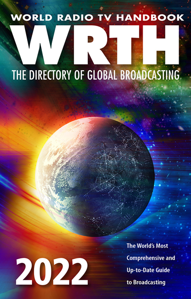
The new 2022 edition of the WRTH has been printed and is shipping.
Purchase your copy of WRTH 2022 directly from WRTH’s publishers, or from a distributor like Universal Radio (US) , Amazon.com (US), or the Book Depository (international).
Bad News: WRTH 2022 will be the final edition by WRTH Publications
WRTH’s publisher, Nicholas Hardyman, shared the following announcement today:
Having produced this book for the past 24 years we are very sorry to announce that WRTH 2022 will be the final edition of World Radio TV Handbook produced and published by WRTH Publications. This was a hard decision to make and one we only made after a lot of discussion. We know that many people rely on WRTH and greatly enjoy getting the new edition every year. We realise that this news will be disappointing for many people.
We want to thank you all for your loyal support over the years.
I know this must have been a very difficult decision for the WRTH team. While it is disappointing news, I wish everyone at WRTH the very best. I’ve gotten to know this team, especially Nicholas, over the years and it’s been an honor to work with them and even write a few of their reviews.
What now?
I believe WRTH will maintain an online presence for years to come. I would encourage you to keep their website bookmarked. Of course, we’ll announce any changes or updates to the WRTH site.
My advice? Don’t hesitate to buy the 2022 Edition!
 Seriously. I can’t tell you how many readers over the years have told me they regretted not purchasing the final edition of Passport to Worldband Radio when it was new. Many didn’t realize that particular year would be the final edition and missed the opportunity.
In this case, we now know the 2022 edition of the WRTH will be the last. We have to assume the company printed roughly the same amount of books that they did last year since the decision was made after the book had gone to print.
In other words, the supply will be similar to last year, but I predict demand will be much higher with readers knowing in advance that this is the final edition.
My advice would be that if you want the 2022 edition, I would bite the bullet now instead of waiting.
Purchase your copy of WRTH 2022 directly from WRTH’s publishers, or from a distributor like Universal Radio (US) , Amazon.com (US), or the Book Depository (international).
Again, here’s wishing everyone at WRTH Publishing the very best! Thank you for so many years of bringing our amazing international radio world into print.