Many thanks to SWLing Post contributor Don Moore–noted author, traveler, and DXer–who shares the following post:
Two Portable Antennas for Remote DXing (Part One)
By Don Moore
Don’s traveling DX stories can be found in his book Tales of a Vagabond DXer [SWLing Post affiliate link]. If you’ve already read his book and enjoyed it, do Don a favor and leave a review on Amazon.
Once upon a time, I had a traditional DX shack with an L-shaped desk and shelves of receivers, radio gadgets, and DX books. Everything I wanted or needed as a DXer was right at hand. Then I retired and was finally able to pursue my lifelong itch for serious travel. But there was no way to carry that DX shack along with me. Fortunately, modern technology was there to help. SDRs are significantly more travel-friendly than my old Sony ICF-2010 (let alone the Drake R-8). Instead of books and bulletins, my DX reference materials are websites and PDF files on my laptop.
I spend several months a year traveling internationally with just a suitcase and knapsack. That doesn’t leave much room for DX equipment. Several years ago I described my approach to vagabond DXing in an article here.
https://swling.com/blog/2019/03/radio-travel-a-complete-sdr-station-for-superb-portable-dxing/
Since writing that article in 2019, I’ve continued to work on making my portable DX shack better and more compact. Recently, I replaced the Elad FDM-S2 with three Airspy HF+ Discovery SDRs. Not only are they smaller and lighter, but I can record three different band segments at once. Next up was rethinking my travel antennas. A wire loop with the Wellbrook ALA-100LN is still, in my opinion, the best travel antenna. But the components are heavy and are now irreplaceable since they are no longer made. So over the summer, I set about testing and comparing both old and new options. But you don’t have to wander the globe for my findings to be useful to you. This can be just as helpful for DXing from a nearby park. That’s how I did my testing.
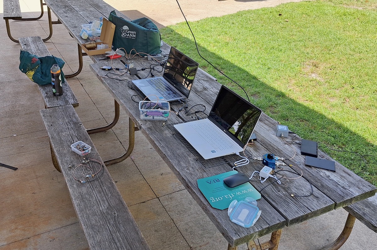
I spent the past summer staying at an AirBnB in the north Chicago suburbs. I wanted a better location for testing so I checked out parks in the area and finally settled on Preserve Shelter B (42.26797, -87.92208) at the Old School Forest Preserve, east of Libertyville in northern Illinois. The shelter was entirely wood, with standard asphalt shingles (rather than steel), and had no nearby power lines. I made four daytime DXpeditions there to do some utility DXing and to run my tests. Here’s a photo of my setup.
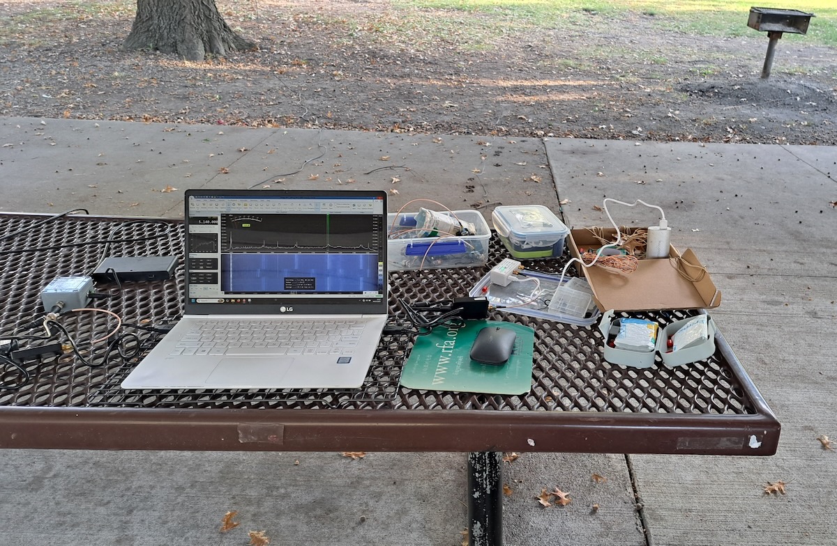
I decided I should rerun the tests at least one other location. So while driving across the US in mid-October, I stopped for a few hours one morning at Park Shelter A (39.11144, -94.86629) in Wyandotte County Park, just west of Kansas City, Kansas. There, I just had a minimum setup.
The Antennas
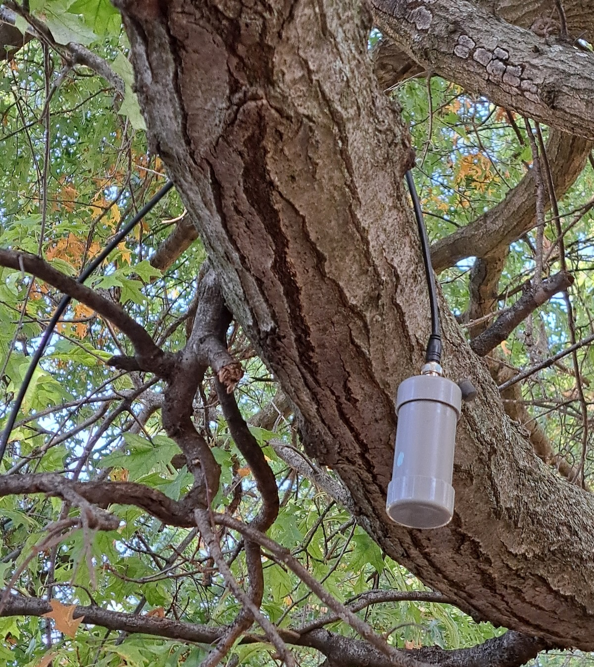
So, what were the antennas I was testing? The first was the tried-and-true PA0RDT mini-whip from Roelof Bakker. The PA0RDT is described in my 2019 article and is probably the most portable quality antenna you can get. To power it I use a battery box and eight rechargeable lithium-ion AA cells.
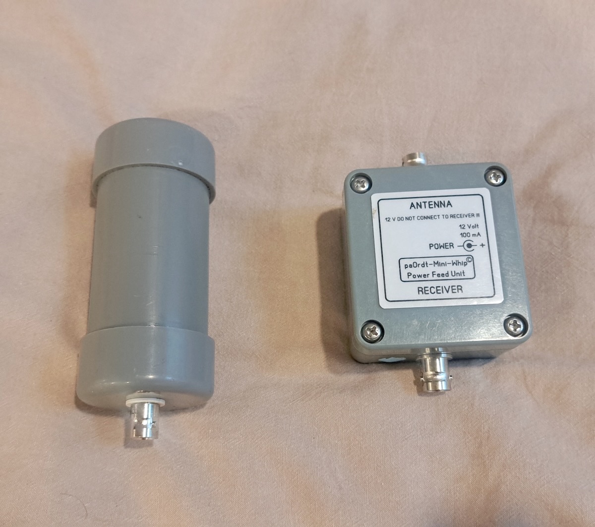 For the traveling DXer, setting up the PA0RDT is as easy as it comes. I just attach the coax cable and throw it over a support, such as a picnic shelter beam or a tree branch.
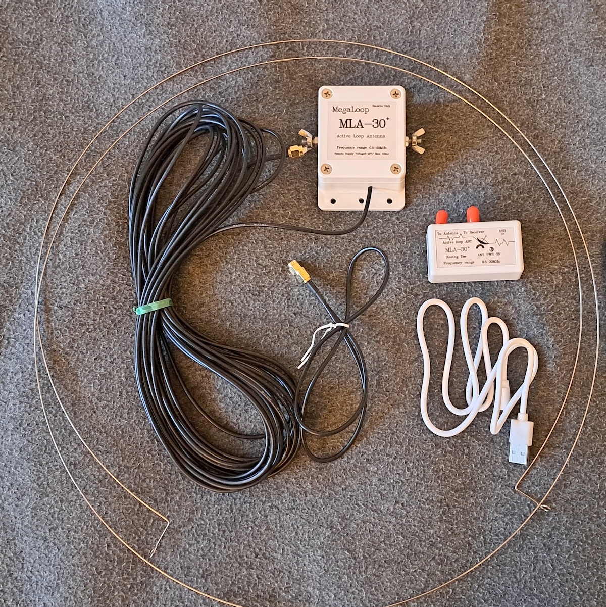
But I’ve always believed that the best antenna is another antenna. That is, every antenna works differently, and therefore the more options you have, the more likely you will have something that works well in any situation. So if I wanted to leave the Wellbrook at home, what might complement the PA0RDT? I contacted my friend Mark Taylor, who I knew had a large collection of the various inexpensive Chinese-made amplified loops. With his help, I settled on the MLA-30+ MegaLoop from DmgicPro.
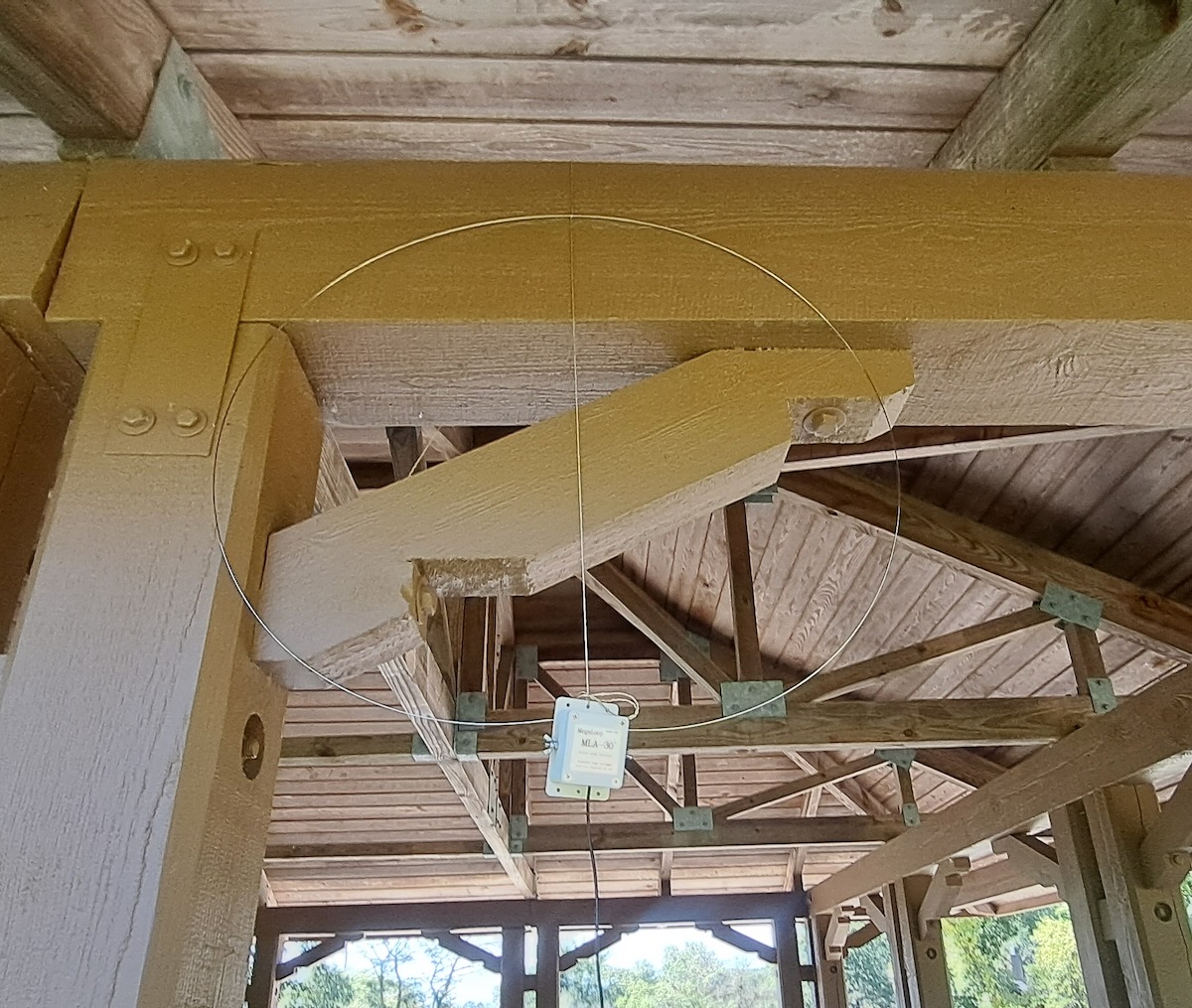
This antenna consists of a steel wire loop that connects to terminals on the amplifier box. The amplifier has a ten-meter coax cable, which in turn is connected to a small bias-T power supply, which gets its power via a USB connection. The MLA-30+ is designed to be used in a permanent installation with some sort of vertical support, such as a PVC pipe. Some users replace the wire loop with copper tubing.
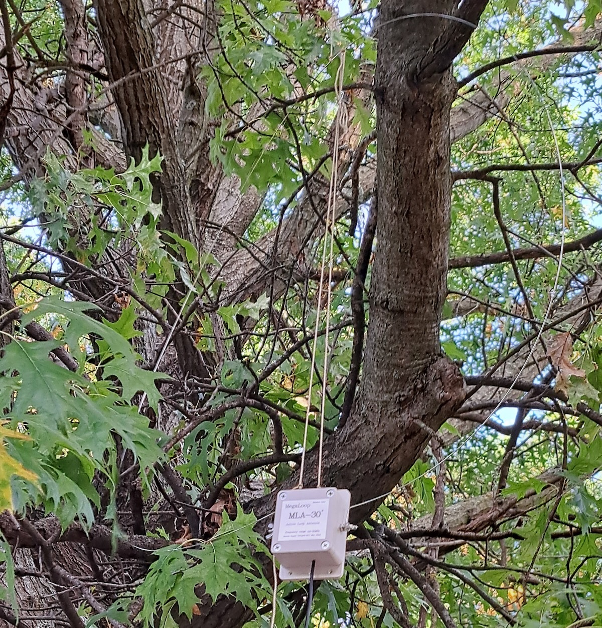
Those options aren’t practical for me, and simply hanging the antenna from the top would cause the steel loop to stretch and deform. So I came up with the idea of tying a strong cord from the top to the bottom of the loop so that the cord, and not the loop, bears the weight. To hang the antenna, I throw the cord over the support, attach the antenna, and then pull it up into place. That works well if you have rear support to hold it in place, such as the beams of a picnic shelter.
It’s a bit more difficult to mount the MLA-30+ in a tree.
Comparing the Antennas
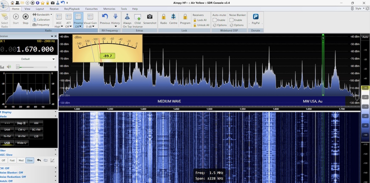
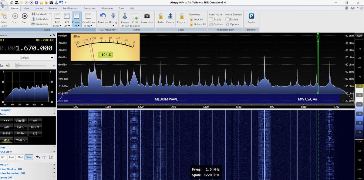
I ran comparisons between the antennas several times at Old School Forest Preserve and then again at Wyandotte County Park. The results were practically the same every time. The images below were made at Old School unless otherwise stated.
The PA0RDT was designed to be a good performer on longwave and medium wave. Unsurprisingly, it shows a lot of signals on the upper end of the medium wave band, even during the daytime. Except for being non-directional, the PA0RDT is an excellent MW antenna.
The MLA-30+, on the other hand, isn’t good for much beyond hearing the strongest local signals on medium wave.
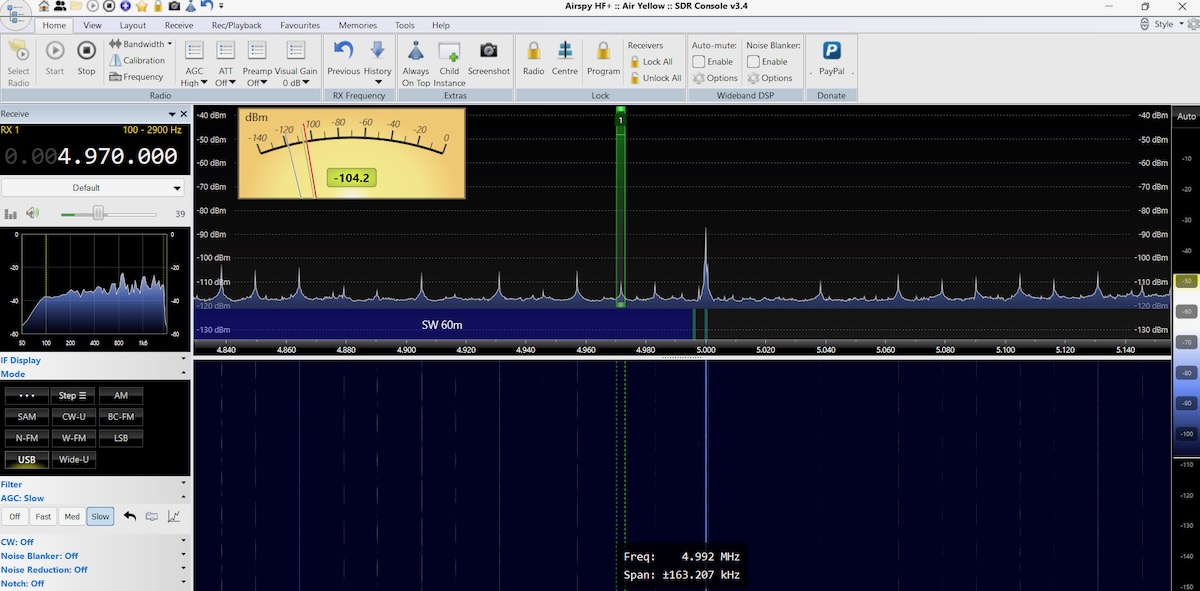
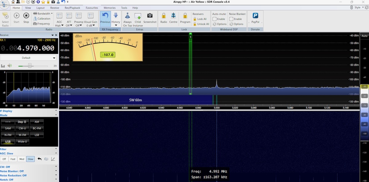
When I ran these tests in the late morning, WWV on 5 MHz was the only signal in the 60-meter band. It had a very listenable signal on the PA0RDT.
But on the MLA-30+, WWV was barely there.
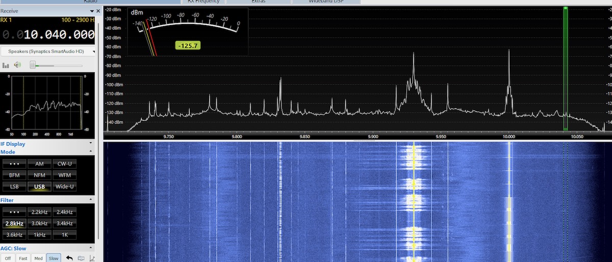
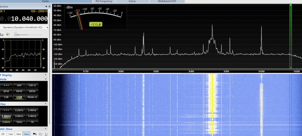
Likewise on 49 meters, CFRX on 6070 kHz was very clear on the PA0RDT but barely listenable on the MLA-30+. But when I moved up to 31 meters, the difference between the antennas mostly disappeared, as in these images made in Kansas. The PA0RDT is top and the MLA-30+ on the bottom.
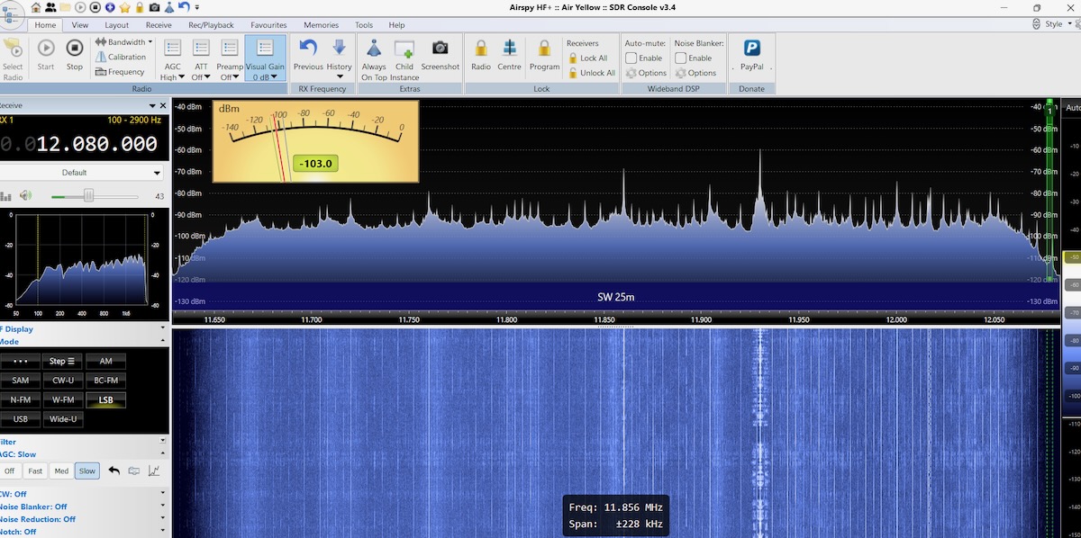
On 25 meters, the PA0RDT is picking up a lot of noise and the signals are not that strong. Nor were signals very strong on 19, 16, 0r 13 meters.
However, on 25 meters with the MLA-30+ there isn’t much noise and the signals are booming in. And 19, 16, and 13 meters likewise had strong signals.
So the PA0RDT is clearly the best antenna for MW and the lower shortwave bands, but it doesn’t do as well on the higher bands. This wasn’t a surprise to me as I’ve always felt that the PA0RDT underperformed above nine or ten Megahertz. The MLA-30+ was abysmal at the lower frequencies but worked better or just as well in the middle and higher shortwave bands. The best antenna is another antenna. Each one performs better in different situations. But I couldn’t help but wonder … was the problem with the MLA-30+ that small steel wire loop?
Look for Don’s Part 2 article next weekend on the SWLing Post!

