By Jock Elliott, KB2GOM
Hang out any place online where shortwave listeners gather, and you won’t have to wait long before you hear something like this: “I recently moved to a condo, apartment, or house where there is a home-owners association. Listening conditions are pretty rotten, and I cannot string up outdoor antennas because of physical constraints or HOA rules . . . help!”
Ever since I got back into SWLing nearly two years ago, I have faced similar issues, as I explained here. During that time, I have frequently read that amplified small loop antennas work pretty darn well, and that has piqued my curiosity.
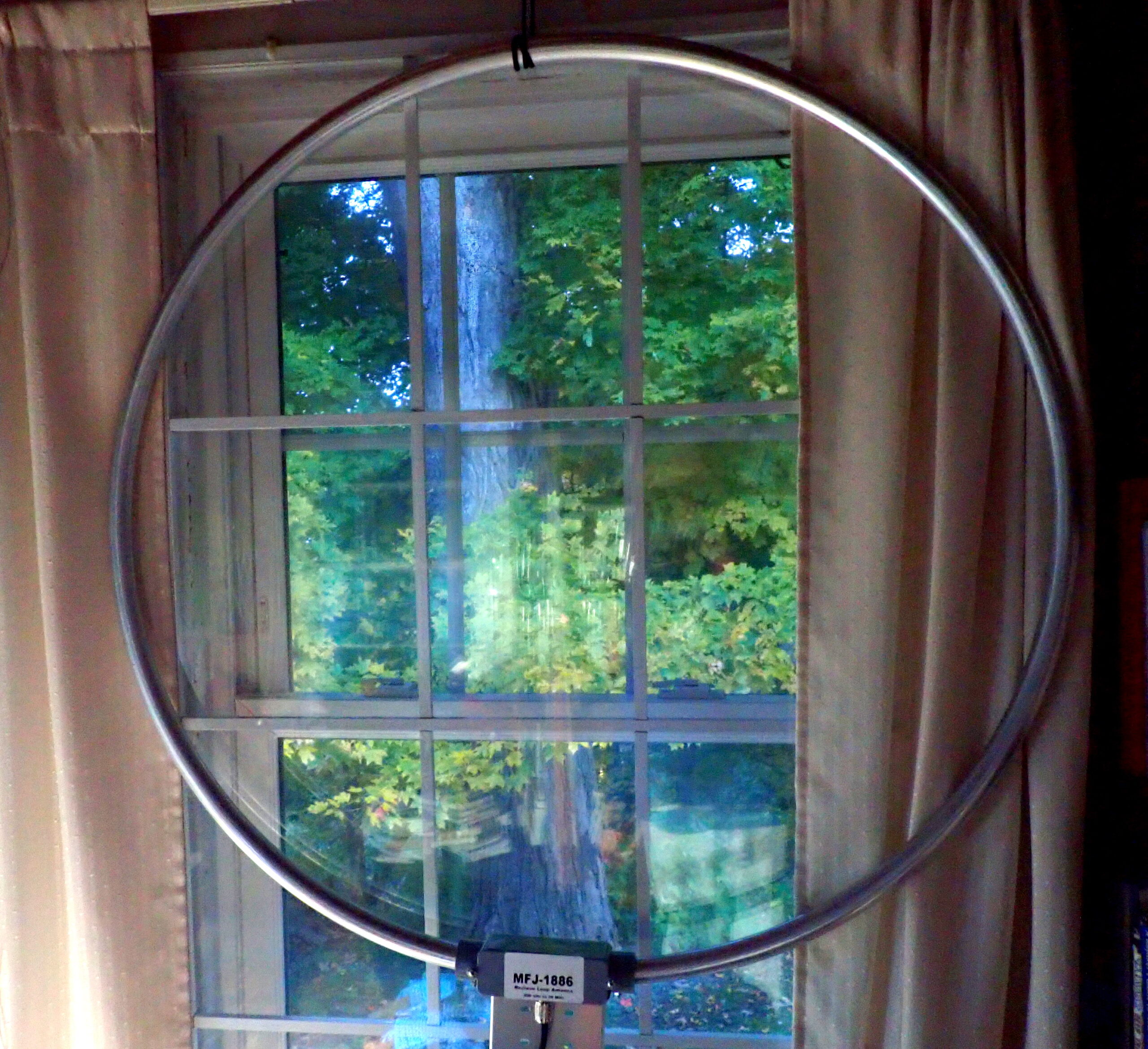
A couple of days ago, the good folks at MFJ (an SWLing.com sponsor) sent me their MFJ-1886 receiving loop antenna. Weighing just 2.5 pounds, the 1886 is a 36-inch-diameter loop of aircraft-grade with an amplifier attached in a weatherproof enclosure. Designed for receiving only, it covers .5 to 30 MHz.
The fit and finish of the 1886 is, in my opinion, great. Looking at the seamless loop and the molded enclosure for the amplifier, I have no reason to doubt what MFJ has to say about it: the MFJ-1886 is weather-sealed, very ruggedly constructed, and mechanically stable under all weather conditions. In fact, you can mount it permanently on any inexpensive TV rotor and direct it from the comfort of your shack . . . it also installs easily on a tripod or handheld mast for portable use.
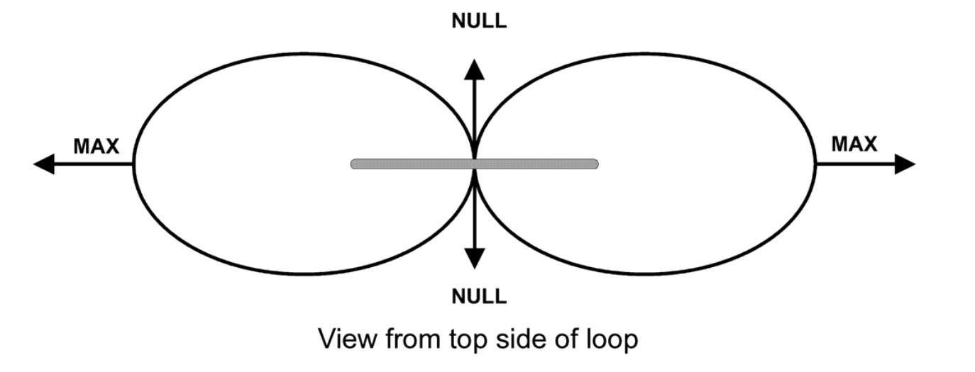
From MFJ’s manual for the 1886 loop.
Important: the 1886 loop is a directional antenna. If you are looking through the open area in the middle of the loop (the flat side, if you will), you are looking in the direction in which the antenna tends to null out signals . . . in both directions. If you are sighting along the edge of the loop (at right angles to the flat side), that is the direction in which the antenna produces the most gain. As a result, you will get the most utility out of the 1886 if you can mount it in such a way that you can rotate it to maximize gain and/or null out noise or interfering signals as needed.
Since my mission was to test the 1886 indoors, I wrapped some parachute cord around the loop and hung it from a screw attached to the top of a window frame. Obviously, I am not getting the most from the 1886 by keeping it in a fixed position (in fact, I was getting maximum gain to the northeast and the southwest), but I did experiment with the antenna hanging from the ceiling so that it could rotate, and I did, indeed, find that signal strength rose and fell as the antenna changed position.
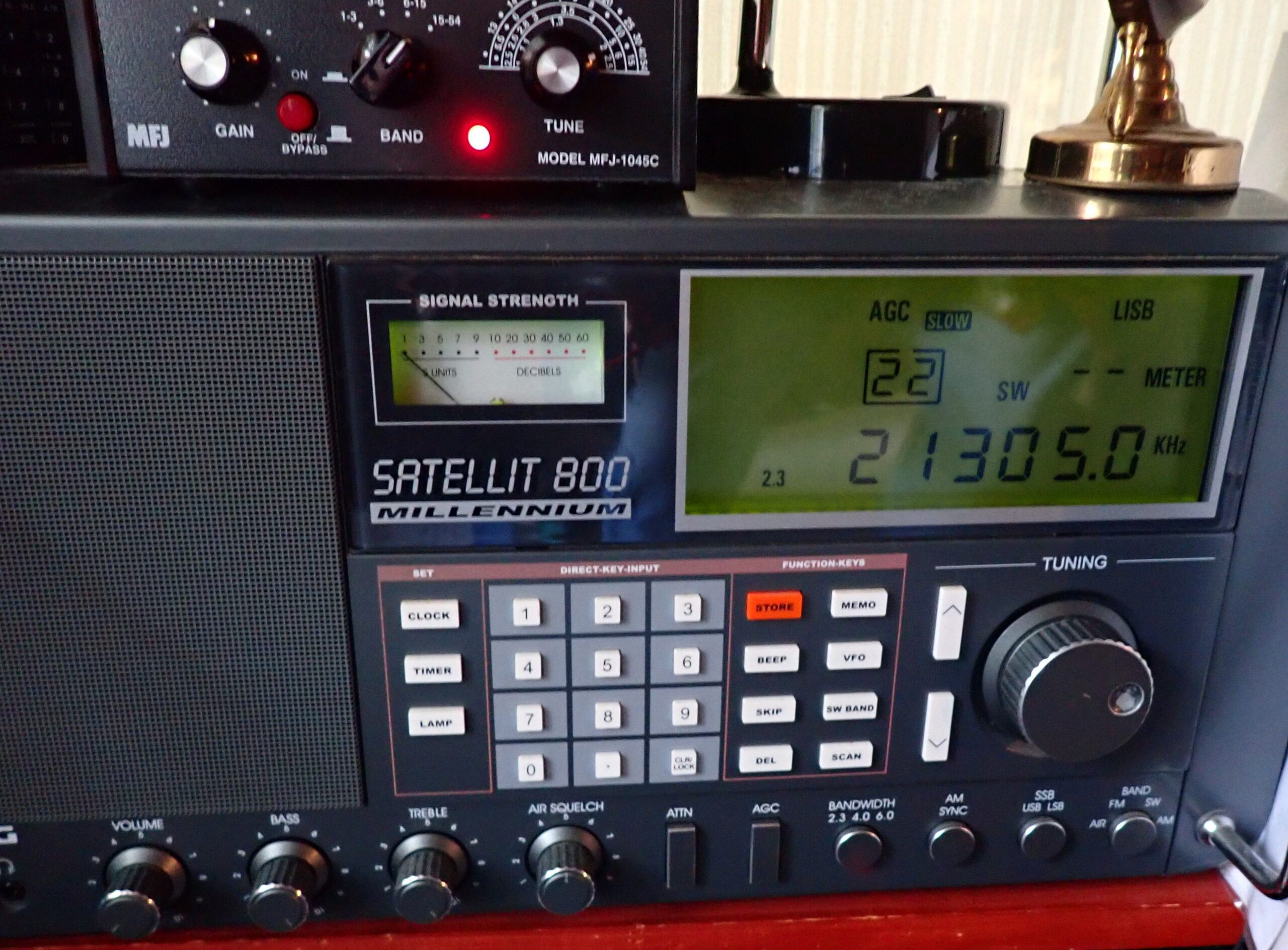
To see how the 1886 performed, I used my Grundig Satellit 800 as a test bed. The Satellit 800 has three different antenna inputs: a wire input, to which I attached the 50-foot horizontal room loop (an indoor antenna which runs around the perimeter of my radio room at about seven feet in the air); a coax input, to which I attached the MFJ 1886 loop, and the four-foot whip antenna that is built into the Satellit 800. By reaching around the back of the radio and sliding the antenna selection switch, I could easily change from one antenna to another and compare the 1886 loop with the whip and the horizontal room loop at various frequencies and settings.
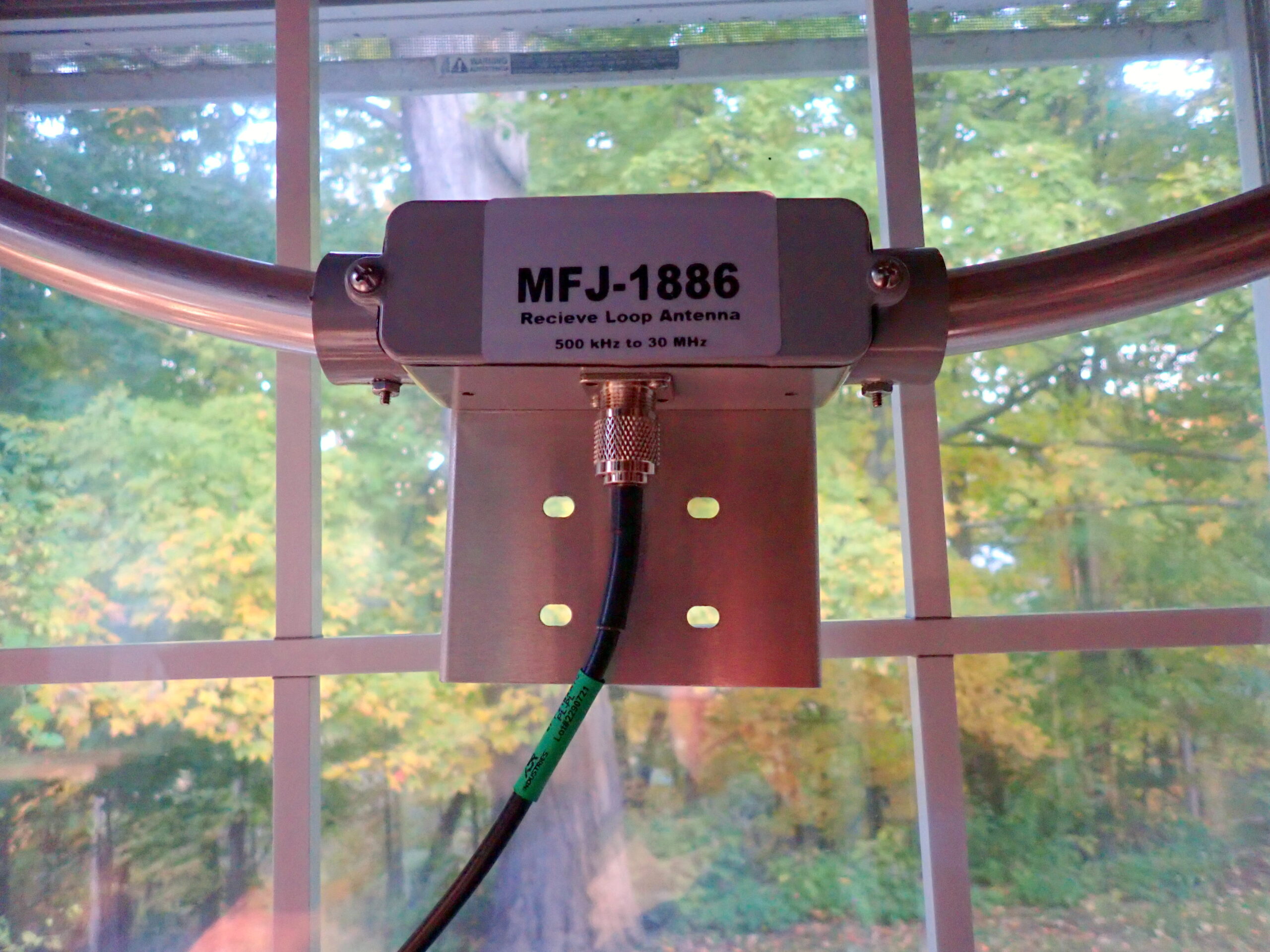
Setting up the 1886 loop is super easy. First, attach a length of coax to bottom of the amplifier box. (The 1886 uses SO-239 connectors.) Attach that coax to the top of the Bias Tee. The Bias Tee supplies power to the amplifier mounted on the loop using the coax and without introducing noise. Run another piece of coax from the bottom of the Bias Tee to the receiver, and, finally, plug the power supply into the Bias Tee and the house power where you are using the antenna.
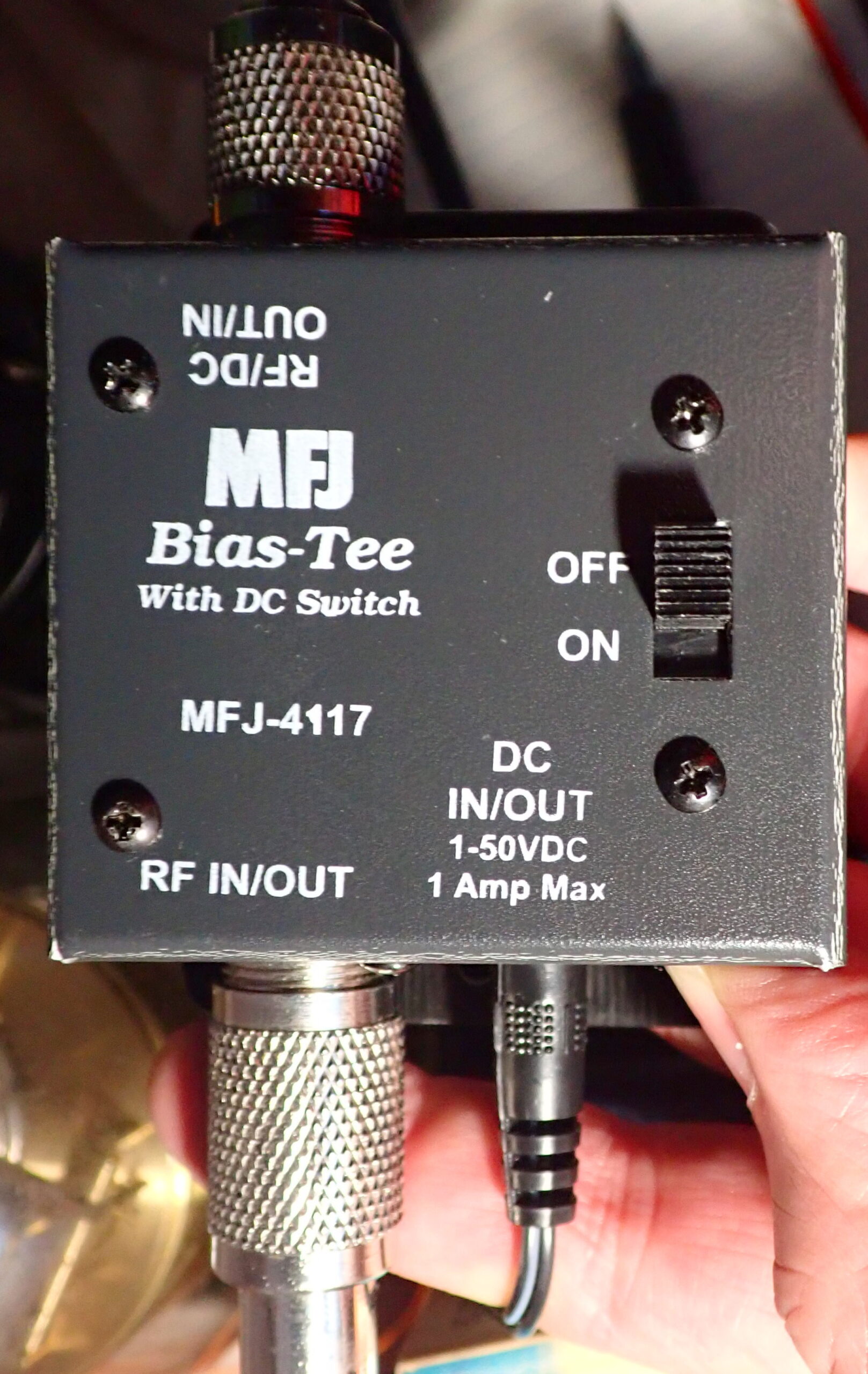
Operating the 1886 is even easier. To hear the signal from the loop without amplification, leave the Bias Tee switch in the OFF position. To hear the signal with amplification, just slide the switch to the ON position. That’s all there is to it. There are no fussy adjustments to make.
So how did the 1886 loop perform? Very well, thank you. In all cases, it clearly outperformed the Satellit 800’s whip antenna, providing more signal with less noise. When pitted against the 50-foot horizontal room loop wire antenna, the 1886 typically delivered more signal and less noise. In a few instances, the horizontal room loop was equal to the 1886 loop in terms of signal strength and low noise. In no cases, did the horizontal room loop outperform the 1886 loop.
Tuning around a bit, I found myself listening to a ham from Spain working DX on the 15 meter band. A little further up the band, a ham from central Bulgaria was dealing with a pile-up of U.S. hams trying to reach him. Of the three antennas options I had on the Satellit 800, the 1886 loop offered the most pleasant listening with more signal, less noise.
Then I tried the 1886 with a couple of my portable shortwave receivers. The Bulgarian ham was still on the air and was marginal on one portable and not hearable at all on the other on their native whip antennas. With the 1886 loop connected, however, the Bulgarian was clear and easy to hear. And – thanks to a ham friend who whipped up an additional coax “jumper” with amazing speed – I tried the 1886 loop with the MFJ 1045C active preselector and found the two made a very potent combo for pulling signals out of the mud.
So, would I recommend the MFJ 1886 Receiving Loop for a would-be HF listener who lives in a condo, apartment, or house with antenna woes? Absolutely . . . even if you have to hang it flat in front of a window. And if you can find a way to mount it so that it can be rotated, even better. (Someday, I hope to try the 1886 outside mounted on an inexpensive TV rotator. For now, there simply isn’t room in my cramped radio space.)
Of course, the performance at your location will depend on the conditions where you live. Nevertheless, I found the MFJ 1886 Receiving Loop to be easy to set up, easy to use, and effective.
Click here to check out the MFJ-1886 Receiving Magnet Loop Antenna at MFJ.
Suggestions for MFJ: offer a kit or accessory that would be make it easy to set the 1886 on a desk or table. Likewise a kit or accessory that would facilitate using the 1886 on a camera tripod seems like a good idea.
Additional note: The SWLing forum is a great place for discussing all things related to shortwave listening.