Shortwave listening and everything radio including reviews, broadcasting, ham radio, field operation, DXing, maker kits, travel, emergency gear, events, and more
Radio Waves: Stories Making Waves in the World of Radio
Because I keep my ear to the waves, as well as receive many tips from others who do the same, I find myself privy to radio-related stories that might interest SWLing Post readers. To that end: Welcome to the SWLing Post’sRadio Waves, a collection of links to interesting stories making waves in the world of radio. Enjoy!
Many thanks to SWLing Post contributors Kris (G8AUU), Tracy Wood, and Dan Robinson for the following tips:
NEW DELHI: “Mahboob Radio Service,” reads the faded panel on a small repair shop near the 16th-century Charminar mosque in the heart of the old town of Hyderabad.
The shop, which has been open since 1948, is filled with thousands of radio sets stacked in the small space where two aging brothers have been repairing radios for as long as they can remember.
The brothers, Mohammed Mujeebudin, 82, and Mohammed Moinuddin, 71, learned the craft from their father, who started selling and repairing radios in the 1920s after a trip to Bombay, where he bought his first set.
“My father started Mahboob Radio Service from Dabeerpura in Hyderabad before moving to the present location in Chatta Bazar in 1948,” Moinuddin said.
He remembered his father’s most prominent customers, such as Viceroy Mir Osman Ali Khan, who ruled Hyderabad until the princely state’s merger with India.
“He was our client, and we would repair his radios. Once the work was done, we would deliver the radio to the palace and receive some 20 or 30 rupees,” Moinuddin recalled.[…]
The companies that own the AméricaTeVé and Teveo television stations have exited U.S. Bankruptcy Court and are preparing to make an acquisition.
America-CV Station Group, Caribevision Holdings, America-CV Network and Caribevision TV Network all filed Chapter 11 reorganization in 2019. The Hialeah-based companies own local stations WJAN (Channel 33 AméricaTeVé) and WFUN (Channel 48 Teveo), along with WJPX (AméricaTeVé Puerto Rico) in San Juan, Puerto Rico, and WPXO in New York.
[…]”América Teve has exited its Chapter 11 reorganization ahead of schedule and has paid off all of its debtors,” said attorney Marcell Felipe, who represents the company. “The company was recapitalized with new equity funded by Carlos Vasallo and the refinancing with Abanca of its valuable real estate holdings.”
Felipe confirmed that the company signed an agreement to purchase Radio Caracol 1260 AM in Miami to create a synergy between the radio station and its TV stations. The Spanish news/talk radio station was being sold by Grupo Latino de Radio, a subsidiary of Spanish media conglomerate PRISA.[…]
SWLing Post contributor, Tracy Wood, notes: “An interesting medium wave note for SWLing Post readers. AM 1260 WSUA in Miami (50kw day / 20kw night) has been used in the past to relay Radio Martí for a few hours at night.”
SAN DIEGO, April 08, 2021 (GLOBE NEWSWIRE) — GBT Technologies Inc. ( OTC PINK: GTCH ) (“GBT” or the “Company”), completed its prototype design of its long range radio mobile system. The prototype mobile unit will be a high-performance radio transceiver system that is designed for data and voice applications. It is expected to enable data and voice communication for long range applications targeting telemedicine support for the Company’s qTerm vital device including audio.
The design of the prototype mobile unit includes a transceiver targeted for systems to operate under licensed/unlicensed radio frequency bands, enabling ultra-long-range applications. The unit is designed to communicate in the HF (High Frequencies) frequencies bands to establish connection with a base unit transceiver through repeater unit(s) to reach ultra-long range. High clarity, signal reliability and security is expected to be achieved through the implementation of advanced circuitry within the system’s components. The design includes embedded software to manage the data and audio communication including data transfer to a backend server to process data. The design also provided for the mobile unit’s design, size and interface, taking into consideration performance and mobility. The operation of the mobile unit is expected to be done via an LCD touch screen providing user’s friendly interface and ease of use. Upon getting team’s FCC certification, an extensive mobile unit’s testing will start. GBT plans to test the entire system within a large city limits and national ranges.
“We are glad to announce that we completed the design of our prototype long range radio mobile unit. The prototype mobile unit is a key component since it is targeted to be portable aiming to bring modern life services around the globe. The design contemplates an acceptable physical size to be carried coupled with a high-power energy source and long range capability. As the system is targeted to work with the qTerm vital device, the design contemplates users being able to send vital information to professional health authorities for quick review and recommendations. In addition, the design has incorporated a voice communication will be available to discuss further steps and actions. We believe that in our days and age everyone should have access to modern amenities and the key is global communication. For us, the most important contribution of such system is the capability to save lives by enabling health and emergency services anywhere on earth” stated Danny Rittman, the Company’s CTO.
There is no guarantee that the Company will be successful in researching, developing or implementing this system. In order to successfully implement this concept, the Company will need to raise adequate capital to support its research and, if successfully researched, developed and granted regulatory approval, the Company would need to enter into a strategic relationship with a third party that has experience in manufacturing, selling and distributing this product. There is no guarantee that the Company will be successful in any or all of these critical steps.
Many thanks to SWLing Post contributor, Dan Robinson, for the following guest post and review:
The H-501: Jewel in the Tecsun Crown, With Some Attractive Features
by Dan Robinson
Since 2020, there has been one Tecsun receiver I have been most looking forward to reviewing, and that is Tecsun’s H-501.
Videos showing the pre-production and mainland China versions of the 501 started appearing online at least a year ago. There are also numerous videos showing comparisons between the H-501 and PL-990x as well as the PL-330.
What I will do here is provide an assessment of the 501 informed by my use of a H-501 just received, the other two Tecsun receivers, and my decades of experience using a wide range of portable receivers. This review is based on initial tests of a H-501x, among the first production units.
Video: Unboxing
HOMAGE TO RECEIVERS OF THE PAST
The elephant in the room with the 501 is, of course, its two large left and right speakers. This reminds one of another Tecsun DSP portable, the PL-398BT with a similar left-right speaker arrangement.
On the left of the H-501, from the top, are the Volume, Treble, and Bass knobs which like the PL-880 and 990x has obvious lineage back to the famous Grundig portables of the 1990’s – the Satellit 500 and 700. Both of those were limited to two bandwidths. Only the 700 had anything approaching usable synchronous detection.
Each of the left hand control knobs on the 501 contains a dot to indicate where you are in the Maximum/Minimum range. At the bottom of the left side is a micro-USB port for when the receiver is used as a computer speaker – quite a nice feature!
On the right side of the 501 you find ports for AM and FM antennas, each with a rubber traction cap, similar to what is found on the PL-990x. There is also a three position sensitivity sliding switch for Local, Normal, and DX modes – that’s one more than usually found.
Knobs on the right side are the Main tuning and Fine tuning, again similar to the PL-990x. At the very bottom of the right side is the 5v 1.0 amp micro-USB charging port.
ERGONOMICS
NEGATIVE: Here I discuss one of two major negatives with the 501. The tuning knobs are embedded quite far into the radio body. Each has a round piece of rubber covering on the knob end surface designed obviously to provide traction, possibly also as a protective measure.
The reality is that on the 501, more seriously on the PL-330, embedding of the knobs so far into the cabinet makes it virtually impossible to undertake rapid tuning using those knobs if you are just placing your finger on the top barrel part of the knob itself!
As you will see in photos and video accompanying this review, holding a finger against the rubber on the end of each knob, or closer to the center, to achieve more rapid tuning. But it’s kind of annoying. On the PL-990x the knobs are somewhat different – extending a bit farther out of the cabinet, but also with the rubber coverings.
So, this is a design point for Tecsun to consider. Surely, it should be possible to come up with slightly different knobs for the 501 that make it more comfortable to achieve rapid tuning. As it is, the knobs on the 501 barely extend beyond the cabinet edge, including the end and rubber cap.
The same goes for the PL-330 – which has knobs that only one half inch in depth, and extending only about 1/16 of an inch beyond the cabinet edge. Part of the attractiveness of the 330 is its compact size and I doubt Tecsun will be moving to put slightly larger knobs on that radio anytime soon. But as it is, using the main and fine tuning controls on the 330 gets you maybe 10 kHz in tuning range.
[UPDATE] I realized after further use of the 501x that Tecsun clearly intended for the rubber knob cap covers to act as traction for tuning. The problems I see: after significant use over time, those rubber covers will lose their stickiness and thus their ability to help tuning will be reduced. Also, the fine tuning knob is smaller — and even using the rubber cover on the knob for more traction, it is somewhat difficult to achieve rapid tuning in 1 kHz mode. Tecsun could help 501x owners on the issue with the tuning knobs by including spare rubber knob caps. But it’s uncertain how the existing rubber knob covers are attached to the original knobs and how easy it would be to replace them when they lose their stickiness.
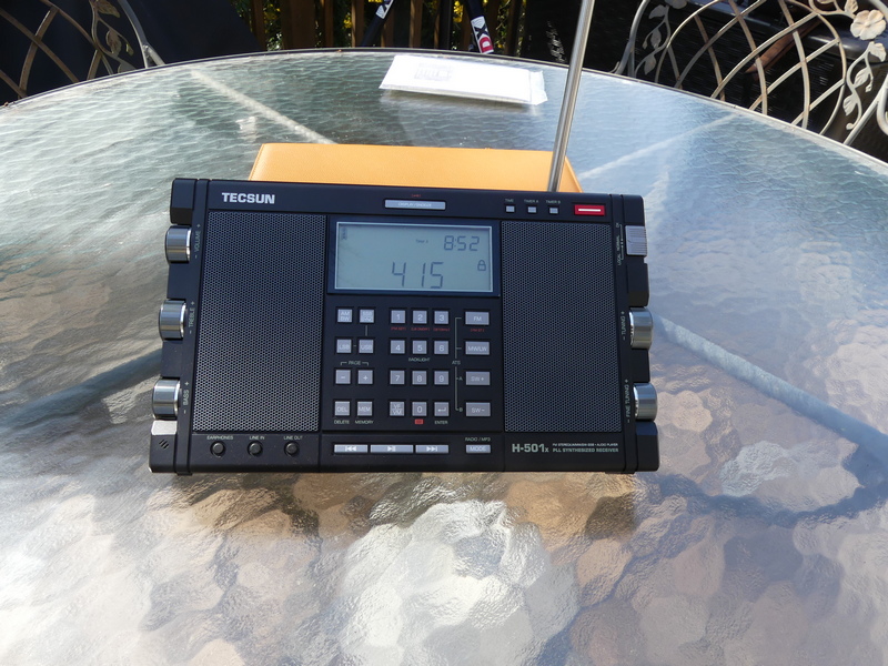
H-501 IMPRESSIVE FRONT PANEL
At the top of the H-501 radio above the LCD display can be found the Display/Snooze/Lock button. On an older Tecsun radio, the PL-880, this button doubled as the calibration adjust control. On the PL-990x this triple function button is located on the top of the radio.
LCD DISPLAY
POSITIVE: One of the big positives of the 501 is the large LCD display. The number digits are absolutely huge and make it easy to read frequencies.
Thanks Tecsun! The display contains numerous bits of information about receiver operation, the signal strength meter, etc.
Below the display is the keypad, with special dual keys for 9/10 kHz mediumwave, Longwave activation, and FM range adjustment. Backlight activation is on the 5 key. At the bottom you have the VF/VM key to select between frequency tuning and memories. To the right are the FM, MW/LW, and SW + and – buttons. These put the radio into shortwave mode and as is the case with the PL-990 and other receivers, activate ATS/ETM tuning.
At the very bottom of the front panel can be found PLAY/PAUSE, RR, and FF buttons for control of SD card audio when using the microSD card, which like on the 990x is located on the bottom of the receiver. According to the manual, by the way, the microSD slot accepts cards of up to 128 GB. Included in the box is a 16 GB SanDisk Ultra card. A reset hole is also on the bottom of the radio.
Finally, at the bottom of the 501 face are rubber covered input ports for Earphones, Line In, and Line Out.
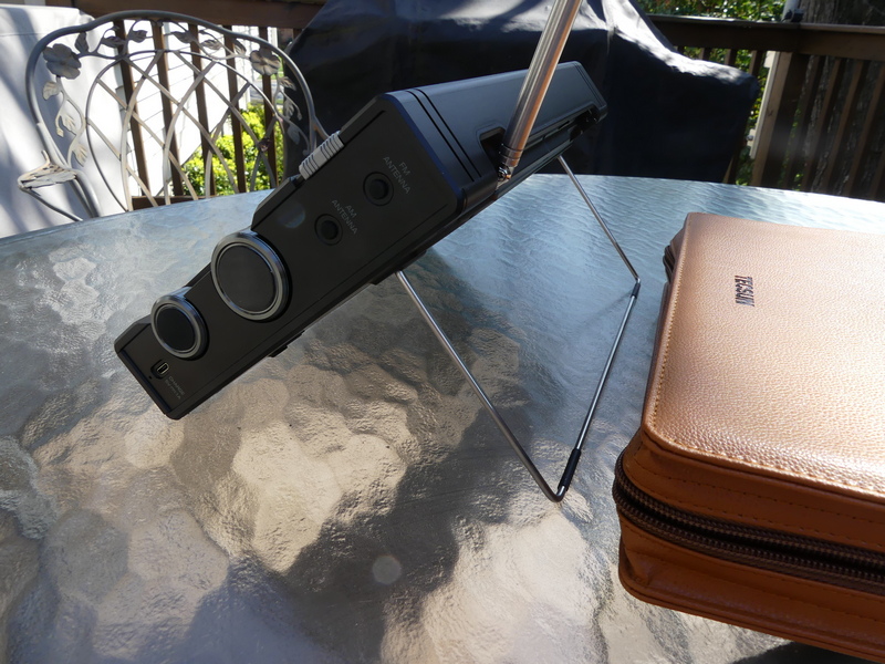
METAL TILT BAIL
POSITIVE AND NEGATIVE: On the back of the receiver, you find the metal tilt bail which folds down and locks into two plastic tabs and can be lifted easily with a finger from an indentation in the cabinet.
This was a good design move by Tecsun, with the following observations: there are no incremental positions on the metal bail as you find on, say, a Microsoft Surface or similar tablet type PC. The only fully stable position is to have the metal bail fully extended back. That places the 501 in a great position if you’re standing or even sitting to a degree. But if you try to place the bail in any middle position you’re in danger of having the radio become unstable. Tecsun should definitely give some thought to a re-design, though the bail is better than the flimsy plastic stands found on the PL-990 and PL-880 and some older portables.
Still on the back of the radio, intelligently, Tecsun marks a screw hole which can be used to remove the telescopic antenna (marked as ANT SCREW). The other screw holes for removal of the back of the radio are also clearly marked. Thanks Tecsun!
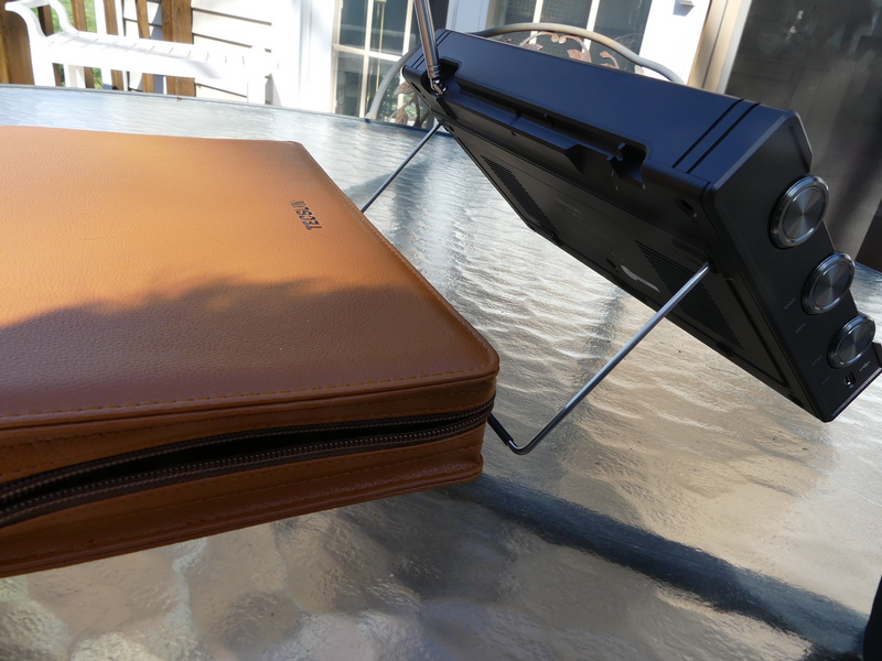
However, one additional partial negative – there are no rubber pads on the bottom back edge of the 501x which will be contacting whatever surface the radio is sitting on while the metal bail is in use. So, if you don’t want that bottom back edge to be scratched, place the radio on something to cushion it.
BATTERY CHARGING
POSITIVE: Another interesting feature not found on other radios: Tecsun has created a dual charging system for the 501 which uses two 18650 batteries.
In viewing numerous videos, I have not seen this discussed much. Basically, this enables you to use the receiver’s internal charging capability to choose which battery you are charging. The manual states that the battery contains space for a “spare” battery. The charging indicator on the LCD display will flash while charging is underway – there does not appear to be a separate display for battery A or B. However, and this is quite a unique capability – while you are using the 501x, the switch changes which battery the radio is using.
It’s not clear to me whether the receiver while powered on is taking energy from one or both batteries simultaneously. As I note in my reviews, and this is amplified in the manual, do not expect to be able to charge a battery internally and listen to the radio at the same time because there WILL be noise.
HUGE WORLD MAP AND RADIO DIAGRAM INCLUDED
Tecsun includes a huge – and I mean HUGE – World Amateur Radio map in a plastic pouch with the manual. On the back of this is a large photo of the 501 with clear English guide points to each and every feature of the radio. In this, Tecsun is really going out of its way to make owning the 501 a special experience.
In the box (see photos) Tecsun includes 2 18650 lithium batteries, a 5 volt double USB A charging cube, a mini to mini cord, a USB charging cable, and to boot, a pair of fairly high quality wired earphones complete with spare ear tips.
PERFORMANCE
Anon-co advises that the H-501x uses a different IC than the PL-990x. No further details were available as of the time of this writing.
This is clearly a sensitive radio, as is the PL-990X. In these days of declining use of shortwave, almost any receiver is going to be able to hear “stuff” all over the bands and the 501x and 990x as well as the 330 are all quite capable in this regard.
In the video, I tune some familiar stations, including Voice of Greece and BBC
and move through the excellent bandwidth options. This is where the 501, with its large dual speakers, excels because if you’re on a strong station – Greece is a great example because of its great music programs – and you have that wider option, it’s really pleasant to listen to.
NEGATIVE: However, one has to puzzle over the decision to limit bandwidth to 6 kHz when in shortwave mode. On mediumwave (AM) you have a 9 kHz option which provides some fine listening. Perhaps Tecsun felt that there are few stations using shortwave these days that would benefit from having a significantly wider option? I would urge Tecsun to make 9 kHz available in shortwave.
SYNCHRONOUS DETECTION
NEGATIVE: I really had some hope that Tecsun would go farther toward
solving the problem of unstable/distorted SYNC mode with all of these recent radios. Unfortunately, it was not to be.
Using SYNC on these radios – though this was not the case with the PL-660 and 680 – involves a delicate dance, requiring using a combination of bandwidth filters and LSB/USB. SYNC works fairly well with some stations, but it really depends on signal level, and to an extent signal level of any station close to the frequency you are on.
There is a 1 kHz fine tune spread when using SYNC after which lock is lost. And still, lock is often lost even when you’re on center frequency and not using
fine tune in SYNC – the signal just becomes distorted. Not fun. The PL-990x has the same issues.
Now, Tecsun has definitely made progress since the horrendous implementation of SYNC on the PL-880, which wasn’t even an official feature. But it’s disappointing that given the design features in the 501, especially the wonderful dual speakers, a way has not been found to resolve this issue which obviously involves the DSP chip that is the brain of the receiver.
Video: Detailed testing of Tecsun H-501x
ANTENNA
NEGATIVE: One of the things the folks at SONY, Panasonic and some other manufacturers did so well was design radios with antennas that nested inside the radio and could be pulled up and out of the cabinet, and because of this, there was clearance from the top of the radio so the antenna can achieve vertical position. Tecsun has not done the same. Antennas on the H-501x, PL-990x, PL-330 swivel but cannot take up vertical position, and of course they are nested on the top of the radio. One would have thought that after years of producing portables, and coming to dominate the portable market, someone at Tecsun would have recognized the importance of antenna re-design. NOTE: the antenna on the 501x is sufficiently long, but on the PL-330 for example, seems to be not long enough.
BLUETOOTH
POSITIVE: Hooray for Tecsun in integrating BT capability into the 501x and 990x. This was such an obvious move and thanks to Tecsun for really hitting it out of the park. Unfortunately, we don’t get the ability to record audio from the radio on to microSD cards – that would truly have been a major step forward
CALIBRATION
The H-501 has the same re-calibration adjustment feature as is seen in the PL-909x and the PL-330. This involves going into LSB or USB mode, holding down the USB or LSB keys until a flash appears, then using the Fine Tuning knob to achieve zero beat on WWV or strong station that is known to be on frequency, then holding down USB or LSB again to have the radio re-zero itself. This is a fine feature that we have seen since the PL-880.
When I first received the H-501 it appeared that the receiver was fairly on zero beat from mediumwave up through 25 meters shortwave. Further testing revealed that re-calibration was necessary, but the degree of error from mediumwave up through 19 meters was not as significant as I have seen on the PL-990x. Re-calibrating at a mid-point of 25 meters appears to be a good mid-point choice, but inevitably, doing re-calibration on shortwave will throw the receiver off by a bit down on mediumwave.
A cautionary note: when undertaking this calibration function be sure to give the radio time to confirm it’s in calibration mode with the FLASHing LCD. Sometimes, the readout will jump a full 1 kHz above or below the frequency you’re zeroing on – if that happens use the MAIN TUNING knob to get yourself back (i.e. 9,704 to 9,705.00) and complete the zero beat operation with the FINE TUNING knob, then hold down LSB or USB to complete.
All of this may be overkill for most people – I am just among those who obsess over having receivers as exactly on zero beat as possible. That’s more difficult or impossible to achieve with older receivers that have no calibration function, such as the ICF-2010 or SW-55 without literally taking those radios apart to access internal points of adjustment. The fact that Tecsun provides this capability in these portables is something we should all be very grateful for.
CIRCUIT LOCKUP
All of the Tecsun radios have a “reset” hole to be used if the receiver is not functioning properly. I had one occasion of lockup with this sample of the H-501x. Rather than using the reset hole, I decided to remove one of the two 18650 batteries, which of course reset the receiver. I have alerted Anon-co to this issue, but it’s hard to tell whether it’s a major problem without having other H-501 units to compare to.
CARRYING CASE
POSITIVE: The H-501 that I received for review from Anon-co came with a beautiful faux leather case complete with a convenient carrying handle. My understanding is that this matches mainland China versions that have been widely seen in videos online.
Anon-co advises that the first batch of 501x to be carried by them will come in a gift box with this PU leather case, possibly to be followed at some later point by a hardcover carrying case. Indeed, a photo can be found online showing the H-501 in a hardcover carrying case similar to the cases for the PL-880 and PL-990x kits.
As of early April, Anon-co advises that while the price for 501x is not set yet, it’s expected to be somewhere in the $310 – 330 range including shipping to the U.S.
AM/MEDIUMWAVE AND FM PERFORMANCE
Not much to say here – I find FM performance on the 501x to be superb, and mediumwave reception is more than satisfactory.
CONCLUDING THOUGHTS
As I noted earlier, these days amid declining use of shortwave by remaining broadcasters, almost any DSP or older portable receivers are capable of producing excellent results for shortwave listening.
Facebook groups devoted to shortwave (they have become the new gathering place and information exchanges for those of us who still love the hobby) are
full of newcomers inquiring about which Tecsun, Degen, or other portables are best.
Often, my advice is to consider older portables that are still quite competitive, especially considering the reduction in the number of stations still on shortwave. These would include such classics as the Grundig Satellit 700/500, the SONY
ICF-2010(2001D), SONY ICF-SW77, and ICF-SW55, along with the venerable Panasonic RF-B65 and SONY ICF-SW100S in the smaller category.
What Tecsun has done with what we have to assume may be the final group of DSP receivers it produces is come up with small (PL-330), medium (PL-990x), and large (H-501) radios that combine extremely attractive features and excellent audio. The H-501x, in effect, is a Grundig Satellit 700 re-born for the 21st century and the path to it was paved by the PL-880.
Though implementation of SYNC in each of these receivers still leaves much to be desired, having this feature is enough to push prospective buyers to choose one or more of these Tecsun units over older portables.
Note that Sangean, which is now producing its ATS-909×2 (though the radio has growing pains and is having its firmware updated by Sangean) seems to have taken note of Tecsun’s dominance of the market and provided multi-bandwith capability, and an improved and enlarged LCD display on the 909×2 along with finer frequency resolution.
In a strange but perhaps understandable decision, Sangean left SYNC mode off of its new flagship receiver. Whether this had more to do with production costs or a decision that synchronous detection really brings little to the game these days, or both, along with other factors, remains a puzzle. It does appear, from early reviews, that Sangean may have improved sensitivity on the 909×2, though this too remains unconfirmed.
But again, even with the negatives I noted here about the H-501x, what Tecsun has accomplished is significant. It has given remaining potential buyers of multi-band portables three superb receiver choices. There are others in the Tecsun line such as the S-8800 and S2000, but of these only the S8800 is something I would recommend.
As I noted in a recent review of the PL-330, had we enjoyed a situation back in the golden days of shortwave in the 1960’s/1970’s/1980’s where a portable provided multiple bandwidths, advanced memory operations, and synchronous detection, DXing would have been even more of an enjoyment than it was. Certainly those Country Heard/Country Verified totals would have been higher!
The H-501x could easily be considered the crown jewel in the Tecsun group with its killer looks, large speakers, and performance equaling the PL-990x. Each of these receivers is arguably an easy choice as a “daily driver” for traveling, though where air travel and TSA issues are concerned, the PL-330 would be a better choice.
RECOMMENDATION: Of the negatives I discuss in this article, only one I would consider fairly huge, and that is the ongoing issue with synchronous detection. If the 501x, like the 990x and 330, were to have this issue resolved that would make it easy to recommend any of the three radios. As it is, the attractiveness of the 501x lies with its beautiful two speaker design. Even with the annoying SYNC issue, I would recommend the radio to anyone who understands the SYNC issue and doesn’t mind and who wants a nice, larger version of the 909x.
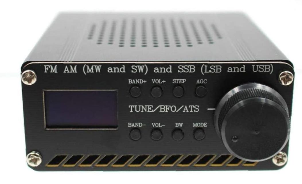
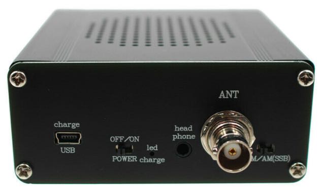
I’ve received a number of inquiries from SWLing Post readers lately regarding an inexpensive Si4732-based mini stand-alone receiver being sold on Amazon and eBay for around $56-66 US shipped.
The radio is based on the Silicon Labs Si4732 DSP chip which provides the following frequency coverage:
FM (64–108 MHz) with RDS
AM/Mediumwave (520–1710 kHz)
Shortwave (2.3–26.1 MHz)
Longwave (153–279 kHz)
It appears the bandwidth selections are 0.5, 1.0, 1.2, 2.2, 3, and 4 kHz.
If 4 kHz is the widest AM bandwidth, that is a bit unfortunate. The radio does have a BFO for tuning SSB and CW signals.
If I’m being honest, even though the price is a no-brainer, I’ve been hesitant to buy it simply because, due to my limited free time, I really do seek enthusiast-grade receivers for review these days. I’m less interested in radios that are cheaply made and lack the sensitivity, selectivity, noise floor, and features an SWL would desire. In other words, I’m a bit skeptical this receiver will be a proper performer.
The frequency range is certainly adequate and Silicon Labs chips are a quality product, but as we know the Si4732 is only as good as its implementation (click here to read the PDF data sheet).
I’m curious if any SWLing Post readers can comment with their experience using one of these Si4732-based receivers. Did it live up to your expectations? How does it compare with, say, an XHDATA D-808 or Tecsun PL-330? Is it sensitive with the supplied whip antenna? Does it have many birdies or other internally-generated noises? Please comment and let me know if this radio is worth checking out!
Many thanks to SWLing Post contributor, Mad Radio DXer, who writes:
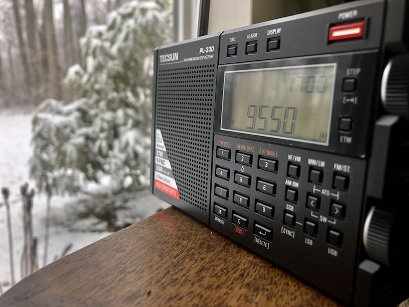
Hi,
I want to let you & your readers know of a Tecsun PL-330 trick that I saw mentioned in the comments section of your blog some time ago which does not seem to have a lot of awareness. This is for using the telescopic antenna for the LW & MW bands, & it works for the 3305 version of the PL-330 which I understand is the export version. The original comment I saw said this also works for the Chinese version of the PL-330, before firmware 3305.
It is very easy to do & instructions are the following…
1. Turn on the radio.
2. Select either the MW or LW band.
3. Press the number 3 key down for a few seconds, until the display shows “CH-S”.
This means the MW & LW bands can now be received with the telescopic antenna.
4. To use the ferrite bar again, press the number 3 key until “CH-A” appears on screen.
This reminds me of the trick used for the Degen DE1103 PLL version which allows reception of the telescopic antenna for the MW band. However, in my opinion this is much easier to use on the PL-330 than the DE1103 PLL which could be very fiddly. Also this trick is most effective on the LW band, as I find Chinese portables are usually very weak on this part of the band which is good news for LW DXers. I hope you & everyone reading find this trick very useful & that it works.
Many thanks to SWLing Post contributor, Michael Ye (BD4AAQ), for the following guest post:
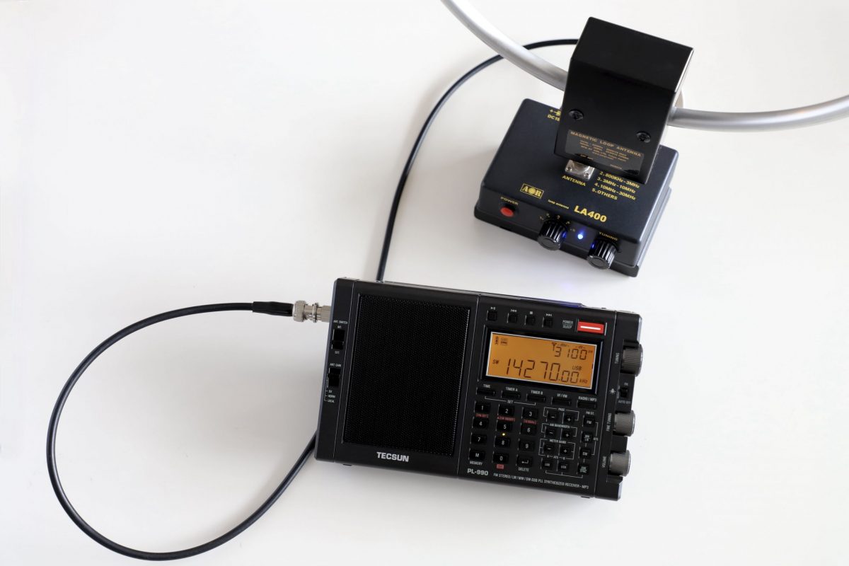
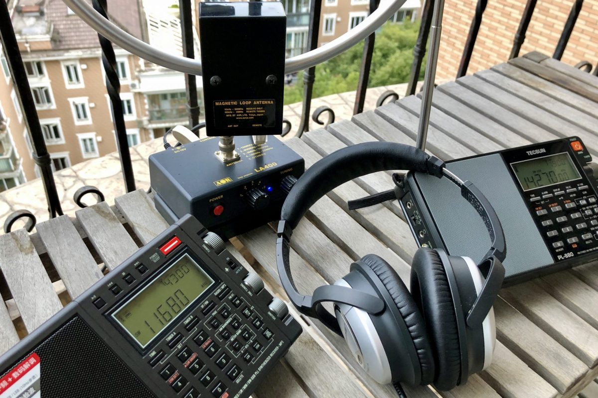
In the Loop: PL-990 and LA400, a Perfect Match
by Michael Ye (BD4AAQ)
PL-990 and LA400
I have been a happy owner of Tecsun’s PL-880 world band receivers for years. In fact I have two PL-880 radios, one sitting at home and the other staying in my car. So, after Tecsun introduced the new model PL-990 in late 2020, it didn’t take me long to decide to purchase one. In this article I will discuss the Tecsun PL-990 receiver working with loop antennas, while referencing some relevant features of the PL-880.
Overall performance of the PL-990
Merely by its model number, it is easy to regard the PL-990 as an upgraded version of the already highly reputable PL-880. As expected, the PL-990 can very much be regarded as a combination of all the existing fine radio features of the PL-880 AND the music and bluetooth additions, with a number of improvements for instance in shortwave and medium wave performance. The ergonomic design of the PL-990 looks and feels different from that of the PL-880 in a number of ways. Although I may prefer the the more slim and elegant appearance of the PL-880, the PL-990 gives a more rugged and durable feeling, among other improvements over the older PL-880.
Working with loop antennas
The PL-990 and the PL-880 side by side
Living on the twelfth floor of a condominium in the crowded Shanghai, I have often been fascinated with loop antennas. As a licensed amateur operator, I have used the MFJ-1786X and have been impressed with its performance. On reception, I also find loop antennas appealing, as they are able to pull in weak signals while noticeably reducing electro-magnetic interference rampant in the urban environment. I have an unbranded shortwave loop antenna which I believe is based on and performs similarly with the AOR LA320. Despite its excellent performance, it is only good for the 5MHz – 15MHz shortwave range. So a few years ago when AOR launched the new LA400 wideband loop antenna, I bought one, which I often pair up with the PL-880 and other radios for shortwave listening, and get satisfactory results!
Antenna Switch on the PL-990
Now, back to the PL-990. When I first tried the PL-990 with the LA400, the results were generally good but not as good as as compared with using the same LA400 on my PL-880. This puzzled me for a day or so until I realised that the PL-990 actually has an antenna switch which the PL-880 does not have. The switch is used to toggle between an internal antenna (i.e. the built-in ferrite bar/telescopic antenna) and an external one (e.g. the AOR LA400). So a new PL-990 user who has often operated the PL-880 when first using the PL-990 could easily ignore the switch which should be pushed to “Ext” when plugging in an external antenna. This explains why the PL-990 may suddenly appear less sensitive than expected.
“Ext” antenna input for all bands
Contrary to the PL-880 whose external antenna socket is only good for shortwave signal input, the PL-990’s external antenna socket works with all bands, from long wave to FM. I found this to be an important and very useful change, and a pleasant surprise for my LA400, which covers a wide range of frequencies from long wave to medium wave to FM and up to 500MHz.
Once the LA400 is connected, the correct band selected, and last but not least the antenna switch turned to “Ext”, the PL-990 and the LA400 work like a charm in the indoor setting, remarkably better than the built-in telescopic antenna. With the loop connected, while there is not much to expect on the long wave band because of very few long wave stations remaining in the world, reception improves considerably on all other bands including on the medium wave and FM bands, as is also reflected on the upper right hand display of the signal strength and S/N ratio readings. Needless to say, performance on shortwave is as good as on the PL-880, if not better (again, remember to push the antenna switch to “Ext” when using it on the PL-990). Using the AOR loop on the PL-990 for FM reception is somewhat different as there does not seem to be a noticeable tuning point. Simply select the “Others” band, which appears to be broad enough for fair FM reception.
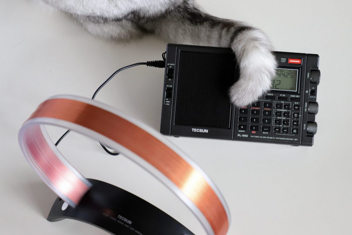
Tecsun AN-200 loop antenna
It is worth mentioning that I have a Tecsun AN-200 tunable medium wave antenna, which I have not used often. As its name suggests, it is for medium wave reception only. I tried it on the PL-990. Works great.
The AN-200 and the PL-990
It is hard to tell which one, the PL-LA400 or the AN-200, fares better, as the signal strength and S/M readings are quite close. They both perform better than the radio’s internal ferrite bar antenna to varying degrees, by improving the signal strength or the S/N ratio or both. The Tecsun loop is a passive antenna, meaning no power is required, making it easy to be used “wirelessly”, by simply placing the loop close to the radio, without having to be connected to the radio via a cable.
Chocolate, our house cat, tries to enhance reception with her tail
It should be noted that in the “wireless” mode of the AN-200 the antenna switch on the PL-990 should remain at “Int” so as for its built-in ferrite bar and the loop to couple with each other.
Many thanks to SWLing Post contributor, Matt Blaze, for the following guest post:
The “Signal Sweeper”, a portable Wellbrook antenna setup
by Matt Blaze
Here’s a very simple construction project that’s really improved my travel shortwave and mediumwave listening experience.
When I go somewhere interesting (whether a day trip on my bike or a longer excursion to an exotic locale), the two things I’m sure to want with me are my camera gear and at least one good receiver. Fortunately, there are plenty of good quality shortwave receivers to choose from these days; the hard part is packing a suitably portable antenna that can do justice to the signals wherever it is I’m going.
I’ve long had a Wellbrook antenna on my roof at home. These wide-band amplified loops famously enjoy a reputation for excellent intermod and noise rejection, as well as an almost magical ability to pull in signals comparable to much larger traditional HF and MF receive antennas. A portable Wellbrook – something I could pack in my luggage that performs as well as the one on my roof, would be just ideal.
Fortunately, Wellbrook sells a “flex” version of their antenna intended for just this application, the model FLX1530LN. It’s essentially just the amplifier of their fixed-mount antennas, equipped with a pair of BNC connectors for you to attach a user-supplied ring of coaxial cable that serves as the antenna loop. This way, you don’t need to travel with the awkwardly large 1 meter diameter ring of aluminum tubing that makes up the normal Wellbrook. You can just bring a compact spool of coaxial cable and configure a loop out of it when you arrive at your destination.
The tricky part is how to actually form a stable loop out of coaxial cable without needing lot of unwieldy supporting hardware. In particularly, I wanted something that could be set up on a camera tripod to be freestanding and easily rotated wherever I happened to find myself wanting to play radio. The key would be finding or making some kind of mostly non-metalic support for the coaxial loop that could be folded down or collapsed to fit in my baggage or backpack for travel.
And then I found it: a humble 3-section telescoping broom handle sold on Amazon for about $15 that’s exactly the right size: the “O-Cedar Easywring Spin Mop Telescopic Replacement Handle“. It collapses to 22 inches (just short enough to fit in my suitcase), and extends to 48 inches (comfortably long enough for a one meter diameter loop).
Normally, a wire loop would need both vertical and horizontal supports in a cross configuration, but by using a reasonably stiff coaxial cable, I figured I could get away with just using the broom handle vertically. I found that LMR400 (the basic kind, not the “Ultraflex” version) holds its shape quite well in a one meter loop supported this way.
At this point, it was just a matter of the details of attaching and mounting everything together into a portable package.
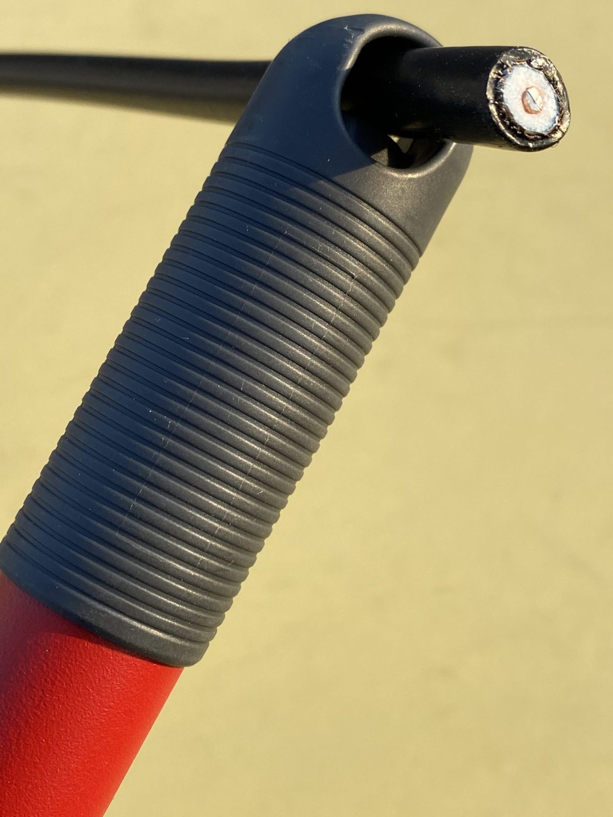
A one meter diameter loop, which is the ideal size for the Wellbrook amp, can be made from 3.14 meters of cable (ask your middle-school math teacher). That’s about 10 feet for Americans like me. High precision is not required here, so I just cut 10 feet of LMR400.
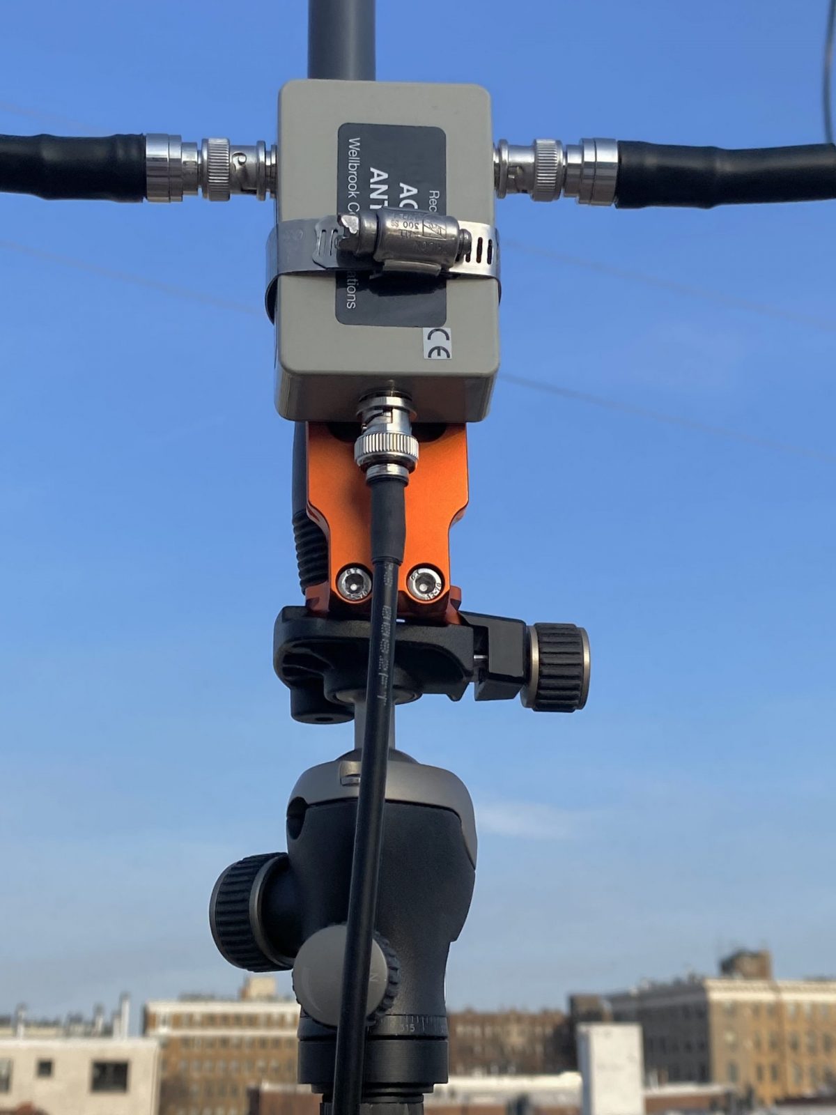
The next step is to attach the middle of the cable to the top of the broom handle. The O-Cedar handle has a loop at the end for hanging it on a hook in your broom closet. It happens to be just the right diameter for LMR400, but not with BNC connectors attached. So you’ll have to thread the cable through before you crimp or solder on the with connectors. (See photo above). I used the Times Microwave crimp-on BNC connectors, which I had some extras of lying around. I also put some shrink wrap on the cable at either side of the broom loop, just to keep it from slipping out and becoming unbalanced, but that was probably unnecessary.
Now I needed a way to to attach the Wellbrook amplifier to the other end of the handle, as well as some way of mounting the whole thing to a camera tripod. My first thought involved a lot of duct tape. But I wanted something more permanent and reusable.
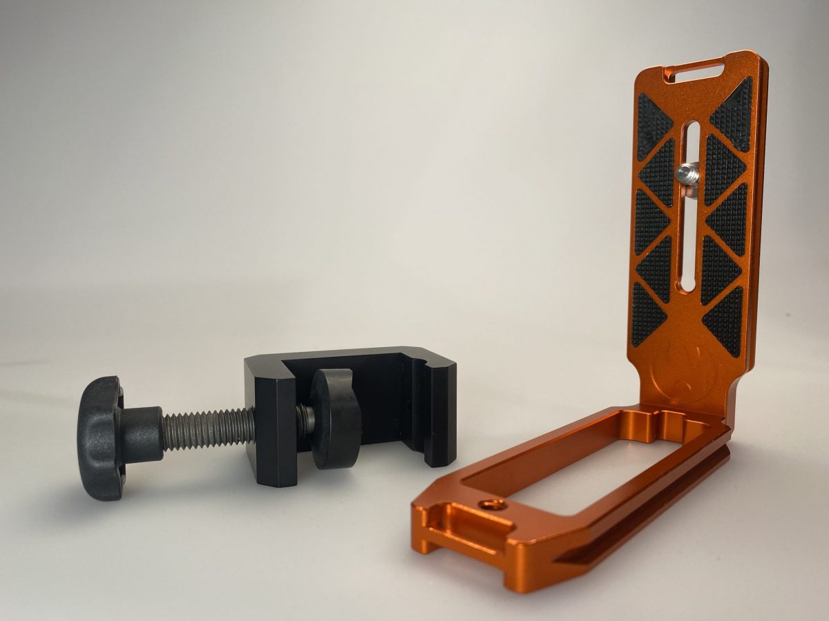
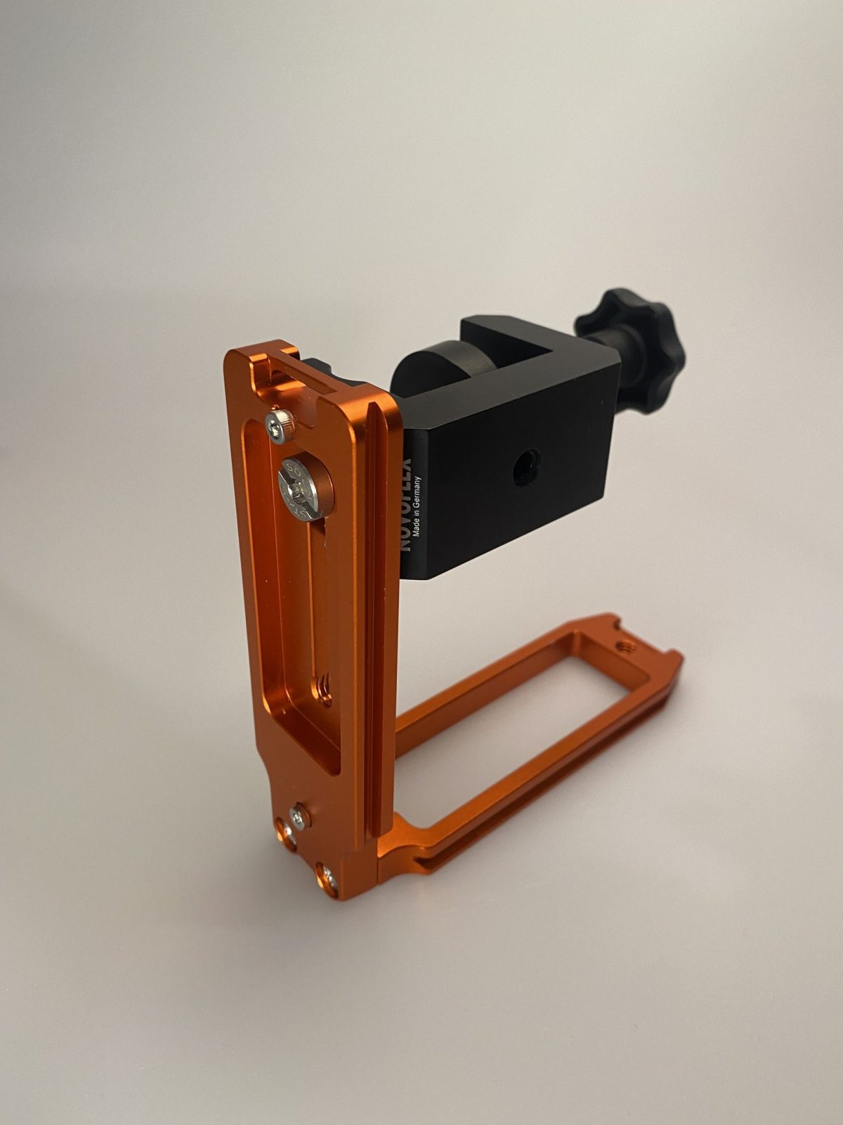
The key is something called an “L-Plate”, which is a piece of hardware intended to allow you to mount a camera to a tripod in either “landscape” or “portrait” mode. It’s basically two tripod dovetail mounts attached at a 90 degree angle. I used one that was in my junk box, but you can buy them new or used on eBay. I also needed a clamp to attach the L-plate to the broom handle. I used the Novoflex MiniClamp 26, which I got from B&H Photo. The clamp attaches to the inside of the L-plate with a captive screw. (See photos)
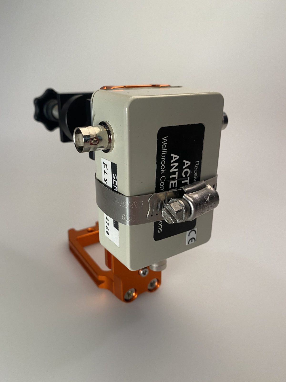
Next, I attached the amplifier to the other side of the L-plate using an ordinary screw-on hose clamp. Easy enough, and surprisingly sturdy.
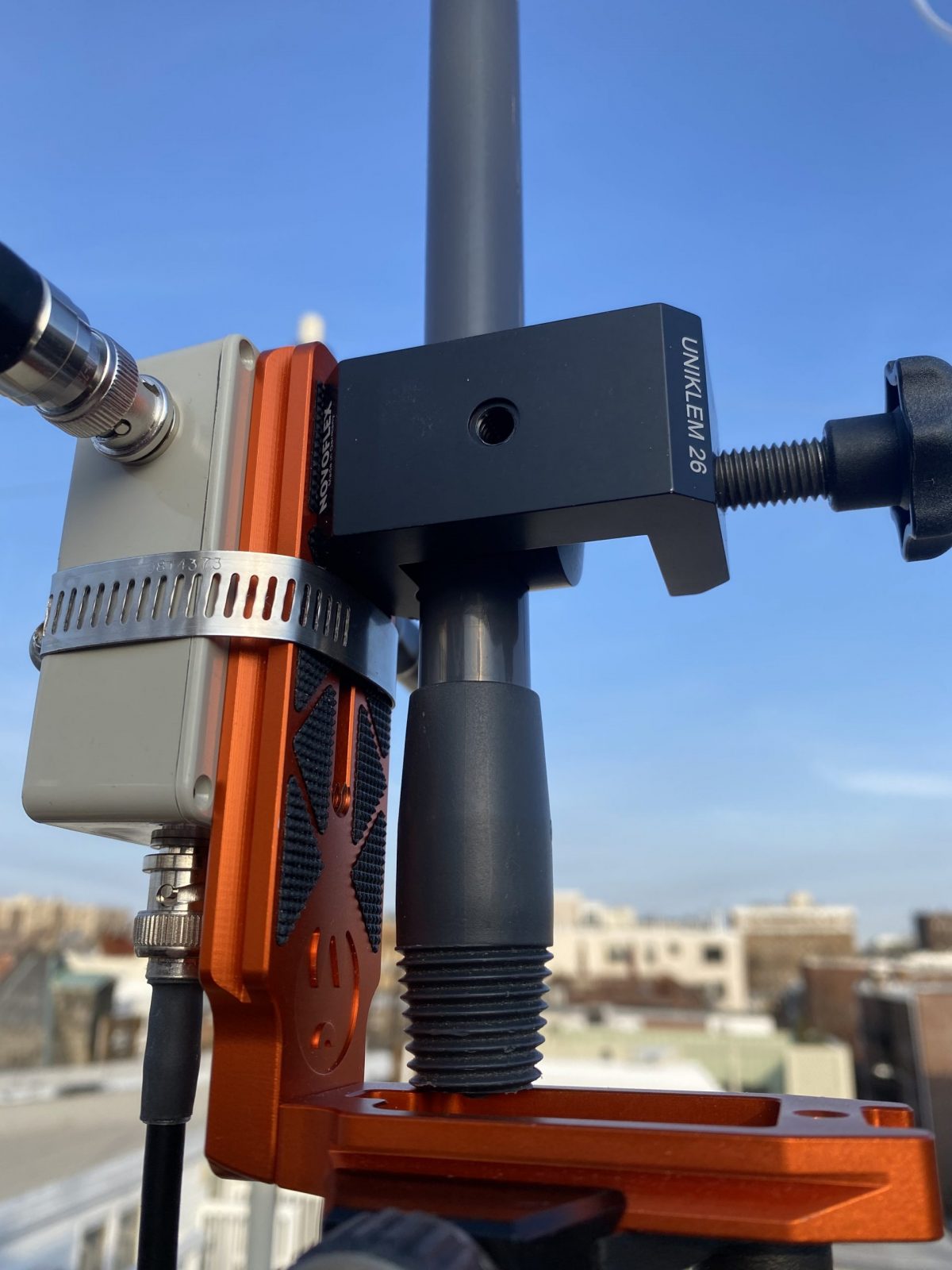
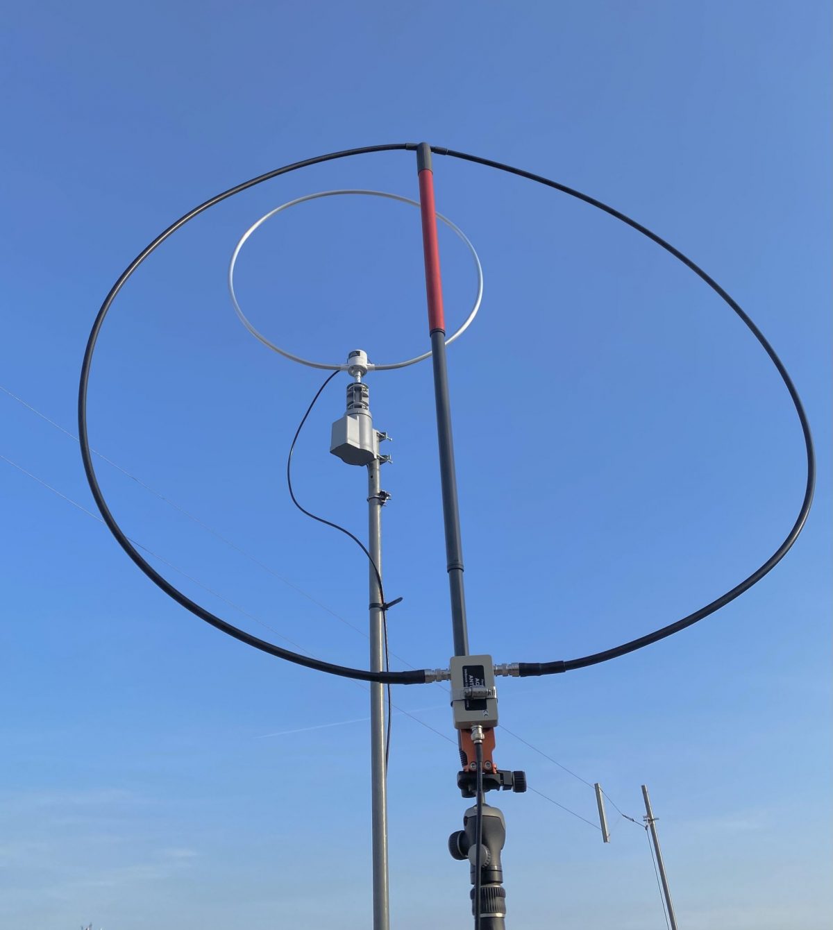
And that’s it. To assemble the antenna, just extend the broom handle to about one meter, allowing for a roughly one meter diameter loop that’s as round as you can make it with the amplifier at the bottom. Then clamp the L-plate to the bottom of the handle so that the handle is just above the base of the plate, and attach to the tripod. (See the photos).
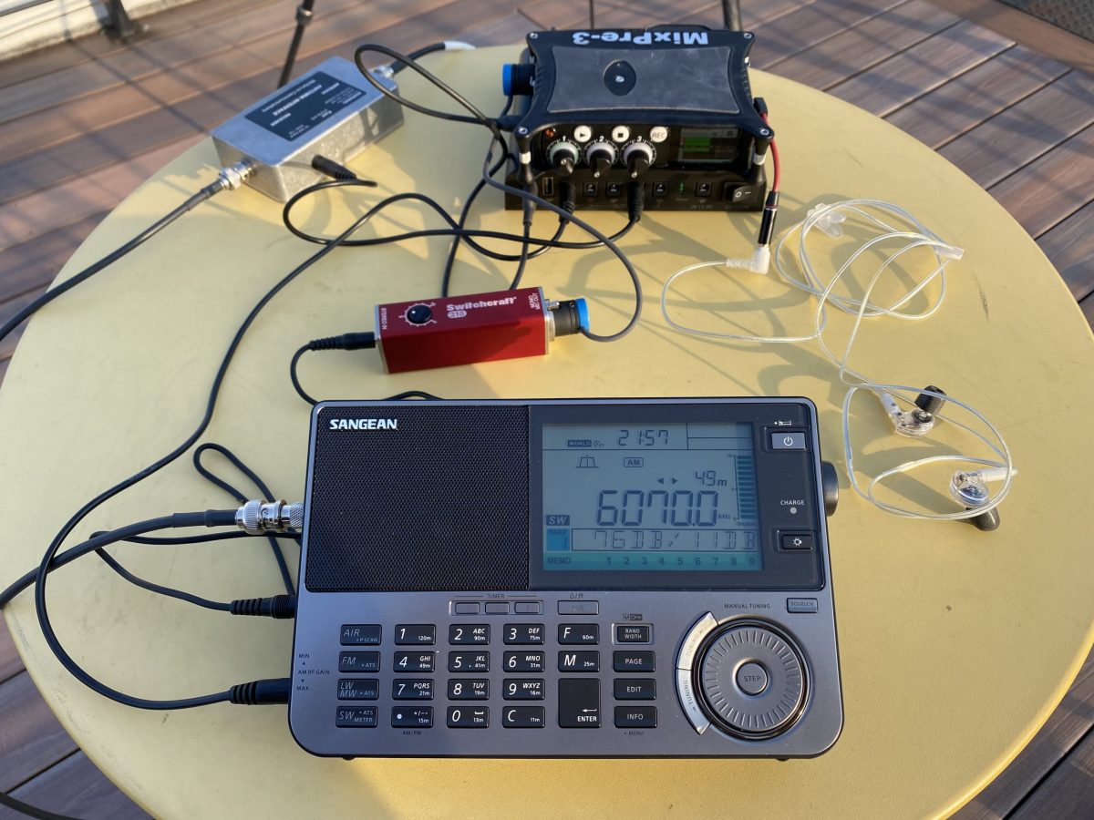
The Wellbrook is powered over the feedline with a 12VDC bias-T injector. So you need a clean source of 12 volts. I use a cheap Talent Cell battery pack (available on Amazon in various capacities). These actually deliver 11.1 VDC (3x 3.7V), rather than the 12V the Wellbrook calls for, but it works fine in practice. I can also use the same pack to power the radio and digital audio recorder.
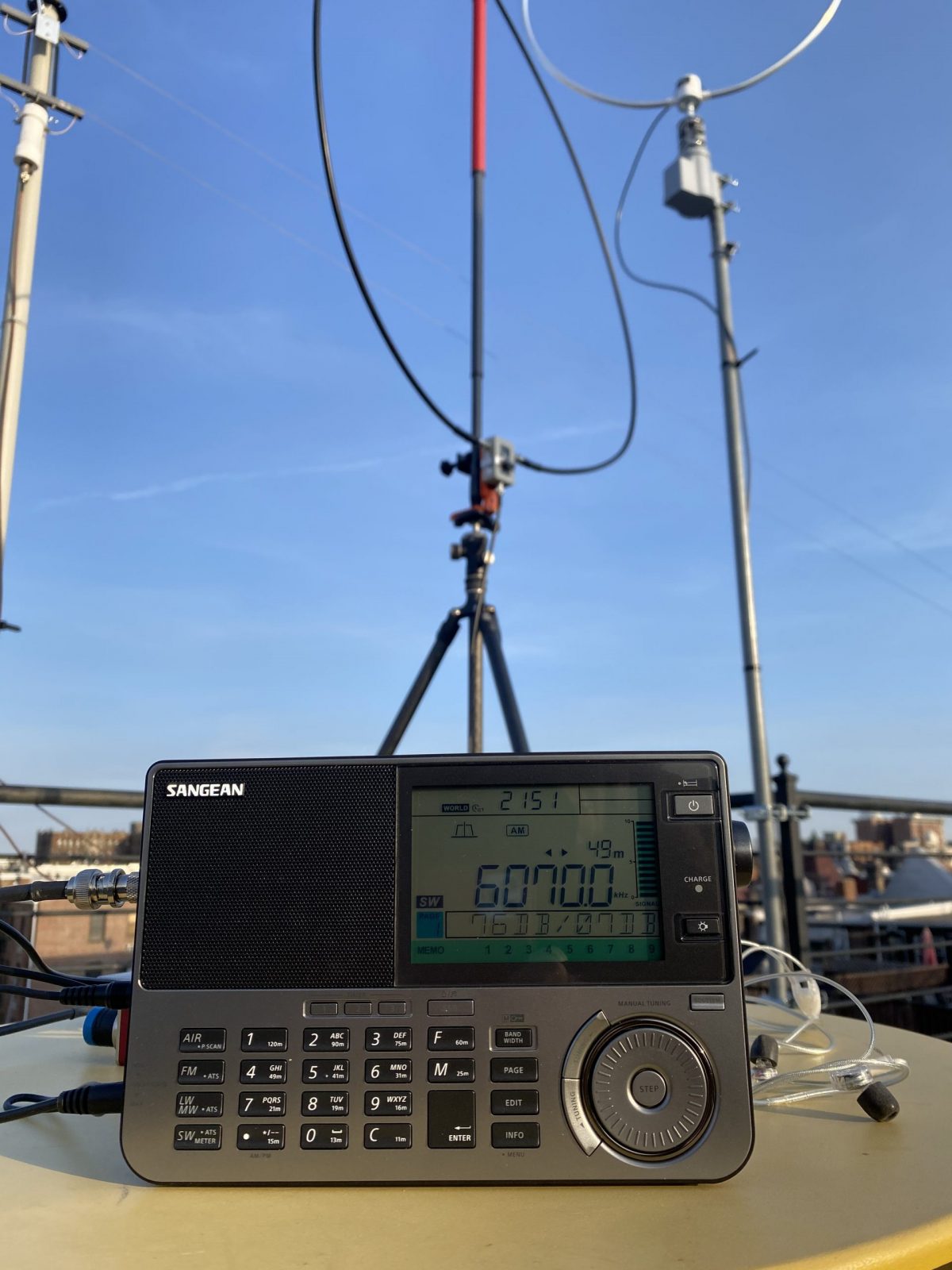
In the photos, you can see the finished antenna setup on my roof, with my permanent base Wellbrook on the rotor in the background. The performance of the two antennas is quite comparable.
(Note that there’s an eBay seller that makes a somewhat similar travel loop. The performance is quite good under normal conditions, but it is a bit more subject to MW overload when near a transmitter site. So I prefer the Wellbrook, which is much less susceptible to overload, I’ve found.)
My usual complete travel setup is either a Reuter RDR Pocket C2 radio or a Sangean ATX-909X (recently upgraded to the X2 model). Both these radios work well with the Wellbrook. I use a Sound Devices Mixpre 3 to record airchecks in the field. In the photos, I’m on a rooftop DXpedition listening to Toronto traffic and weather from CFRX on 6070 kHz on a warm later winter afternoon.
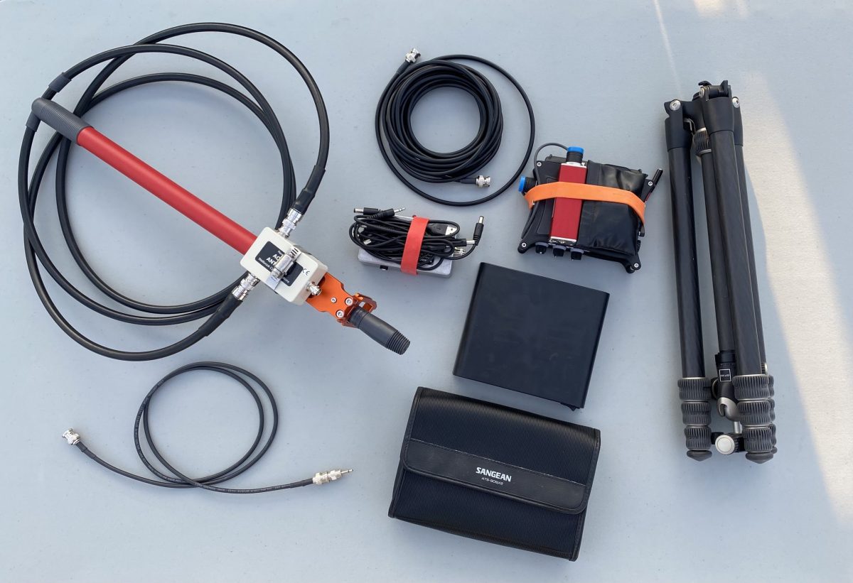
The whole setup breaks down for travel pretty easily, and fits easily in my suitcase, backpack, or bike bag (see photos). I usually bring a larger tripod than this if I’m also taking my camera.
The Wellbrook setup has really made bringing a receiver into the field a lot easier and less uncertain. There’s no worry about finding trees or other supports for wires, and packing and unpacking is quick and easy. Have fun!