Category Archives: Photos

Guest Post: A visit to Museo Marconi in Villa Griffone, Pontecchio, Bologna


Many thanks to SWLing Post contributor, Ferruccio Manfieri (IZ1096SWL), who shares this report and excellent photo tour from a visit to the Museo Marconi in Bologna, Italy in 2018.

Today is International Marconi Day, so this is a very welcome, and timely post:


A visit to Museo Marconi in Villa Griffone, Pontecchio, Bologna

by Ferruccio Manfieri (IZ1096SWL)

Bologna, in Northern Italy, is renowned to be the seat of the oldest University in Europe and in the world (the Alma Mater Studiorum) and its historic, artistic and culinary heritage. From a scientific perspective, Bologna is the birthplace of Guglielmo Marconi as well as the place of his first experiments in transmission.

The inventor, born in Bologna on April 25th, 1874, was the son of an Italian father (Giuseppe, a wealthy landowner) and an Irish mother (Annie Jameson, of Jameson’s Whiskey family). At the age of 20, Marconi began to conduct experiments in radio waves, building much of his own equipment in the attic of his home at the Villa Griffone in Pontecchio (in the Bolognese countryside).

Marconi received his final resting place in Villa Griffone Mausoleum, an enterred crypt hosting his porphyr sarcophagus. The building was donated to the Guglielmo Marconi Foundation in 1941 after the  death of the inventor (on the 20th of July 1937).

Sadly, Villa Griffone and the Mausoleum suffered heavy damages from WWII bombings and pillages and were patiently rebuilt in post-war years. Today, Villa Griffone is reborn as a hub of research and divulgation activities, hosting Guglielmo Marconi Foundation, the Marconi Museum, a library and two research groups on communication systems.

On the 26th of april 2019 I visited with my family the Museum hosted in the original building (a short trip from Bologna, 20 minutes by public transport)

Villa Griffone and the Marconi Mausoleum

The visit began with a nice stroll in the Villa gardens, home with the nearby hill of the Celestini of the first long-range and not in line of sight transmission experiment in 1895. Marconi managed to send signals over a distance of 2 km, beyond a hill situated between the transmission equipment (to which he had added a grounded vertical antenna) and the reception apparatus (characterised by an extremely sensitive coherer).
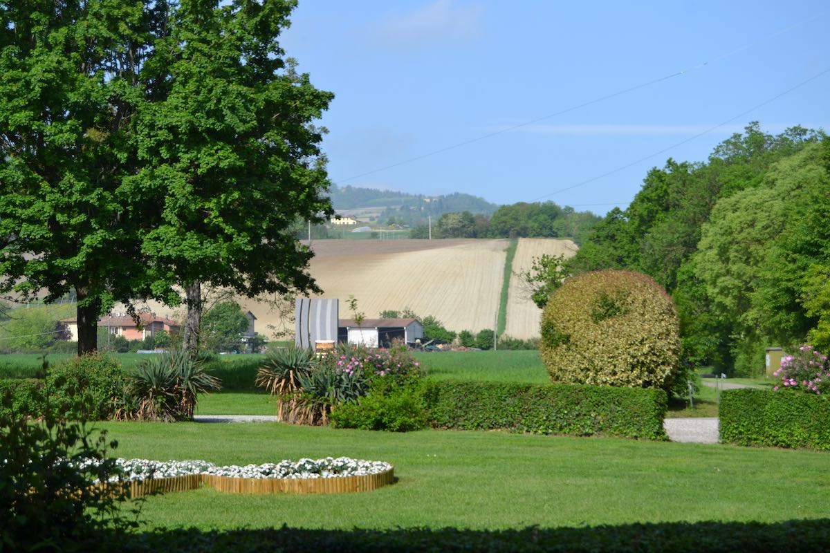
Villa Griffone gardens and “Hill of Celestini”

We were in the very spot Marconi was when he transmitted his three signals to the receiver operated by his brother and the gardener behind the hill. Nearby, the replica of eight meter wooden pole with the attached metal boxes used as antenna.

Marconi’s first “long range” antenna – replica

This experiment in universally aknowledged as the birth of radio transmission (and, by the way, the rifle shot used as a confirmation of the reception was the very first QSL…).

Our valent host and guide to the visit was the Director of the Museum, Barbara Valotti, who thoroughly described us (with knowledge, passion and communication skills) the historical framework of Marconi’s biography and works. A more engineering oriented and hands-on visit to the working replicas laboratory was subsequently hosted with passion and knowledge by Adriano Neri I4YCE.

In the Auditorium Dr. Valotti  showed us two videos on the first transmission experiment and on the Republic incident in 1909, on of the first application of Marconi radiotelegraphy in an incident at sea, whose success (no lives were lost in the aftermath of the collision thanks to the coordination of rescue efforts via radiotelegraphy) gave a boost of popularity to radiotelegraphy and to the engineer, eventually leading to the Nobel prize in physics later that year.
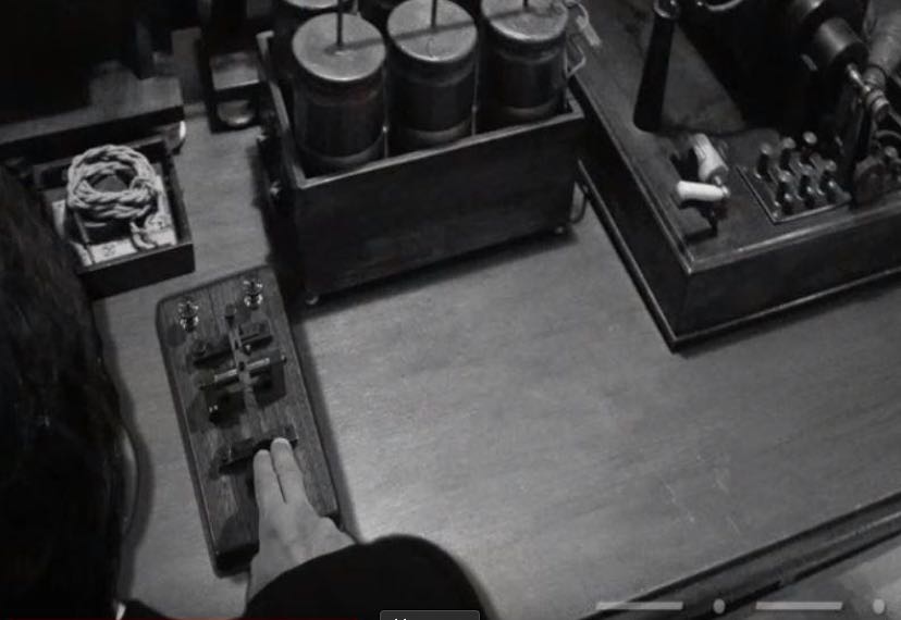
A frame of the “Republic” video

This part of the visit emphasized his interest in real technological applications of his inventions and their commercial potential. Marconi was a “modern” mix of engineer (with an unhortodox, non-academic formation) and entrepreneur, ready to see the new potential applications of technologies in the society.  Interestingly, Dr. Valotti underlined that the main focus of Marconi research was always the point-to-point trasmission and not the broadcast.

Hanging on the ceiling of the auditorium, a replica of the kite used by Marconi to lift an emergency antenna in the first transoceanic transmission from Poldhu to St Johns Newfoundland in 1901.
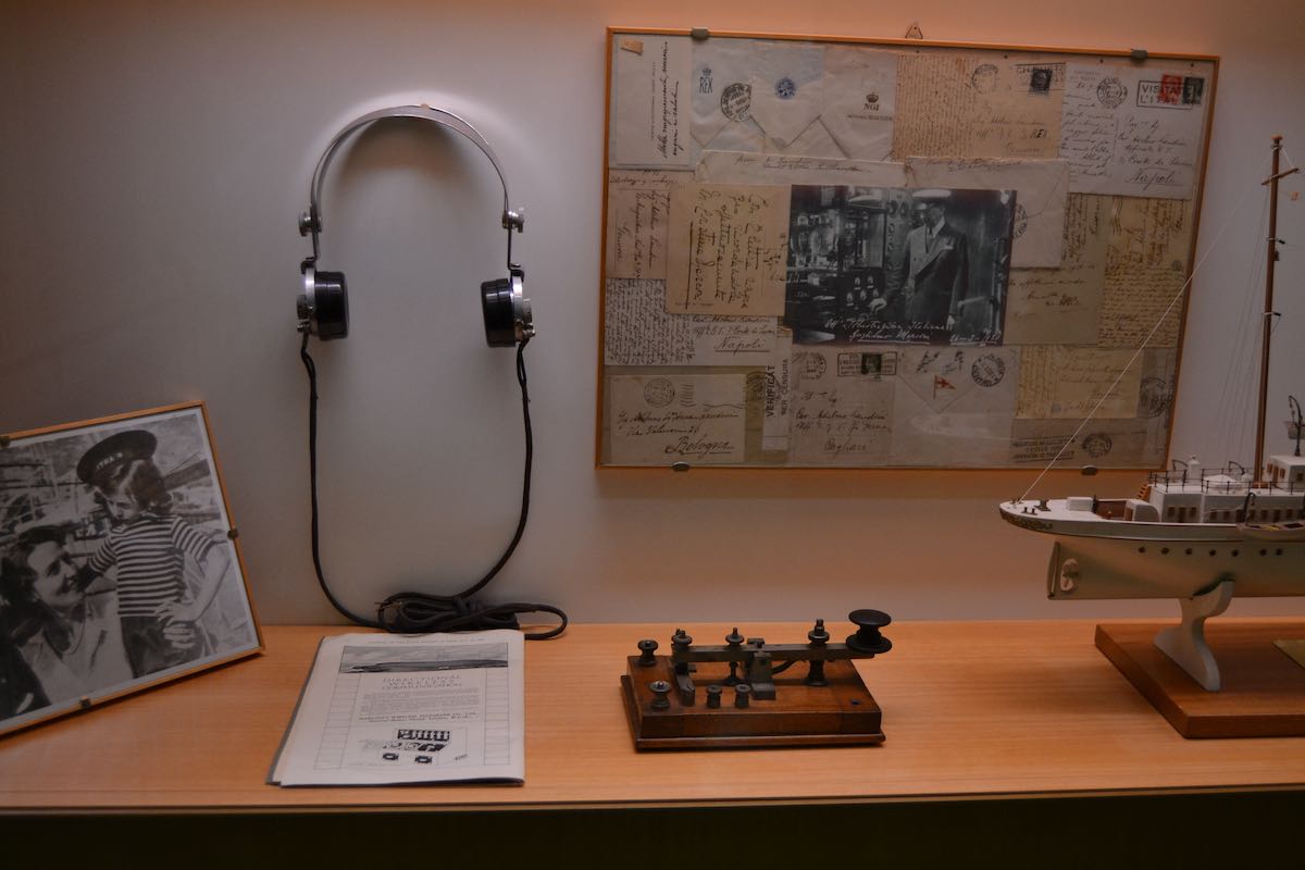
Yacht “Elettra” – memorabilias

The visit continued to the “silkworm room”, the original room (once used to breed silkworms) where Marconi held his laboratory and performed his experiments. The room was full of instruments replicas to show the laboratory as in the young Marconi years.

“Silkworm room” – Marconi’s first laboratory (original place,  instrument replicas)
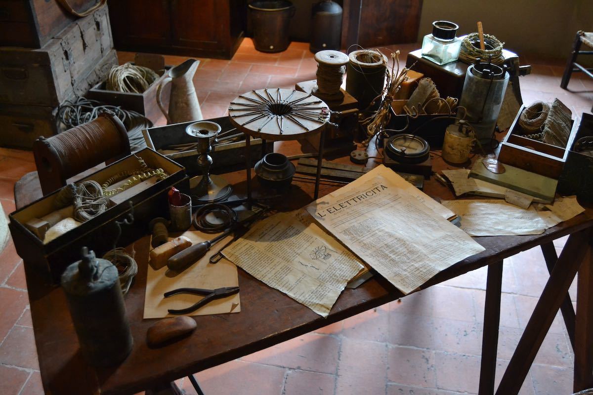
“Silkworm room” – Marconi’s desk (replica)

It was also possible to replicate the main experiments with educational working replicas.
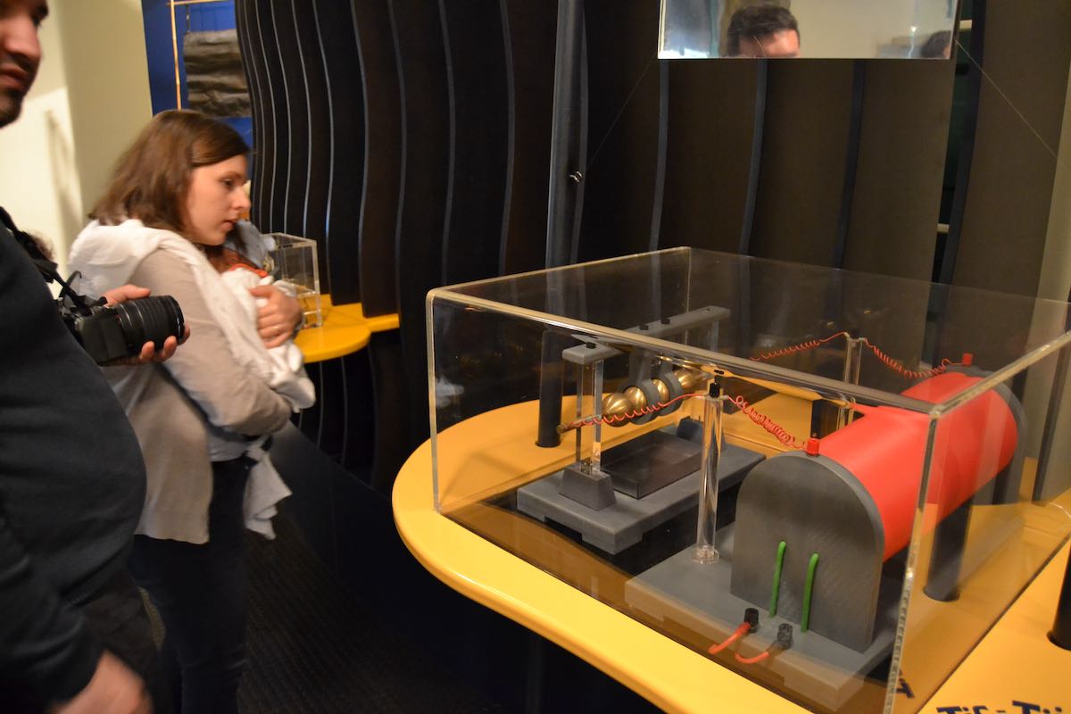
Marconi transmitter – educational replica
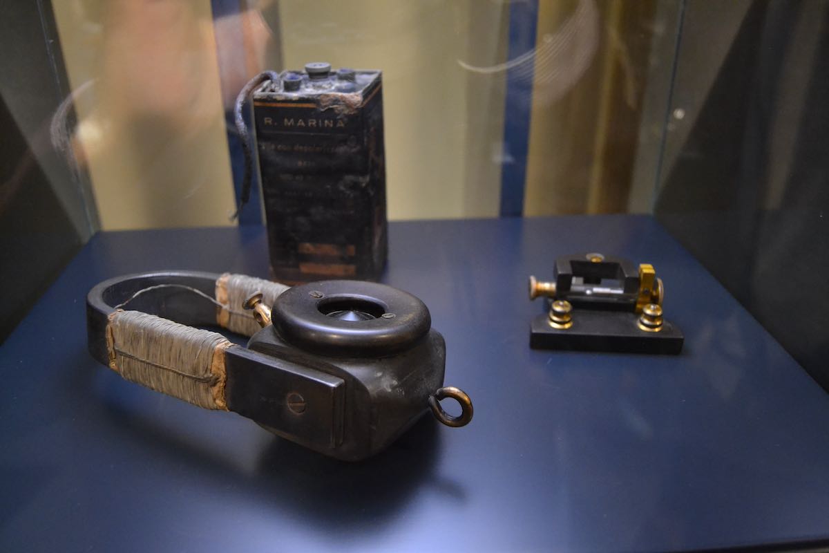
Headphone and coherer used in the first transoceanic transmission (replicas)

The second phase of the visit was a more engineering-oriented explanation of the principles of radio telegraphy conducted by Adriano Neri I4YCE in a didactic laboratory on working replicas of the main epoch instruments.

Experiment table with working replicas: coherers, a wire decoder, a Marconi receiver
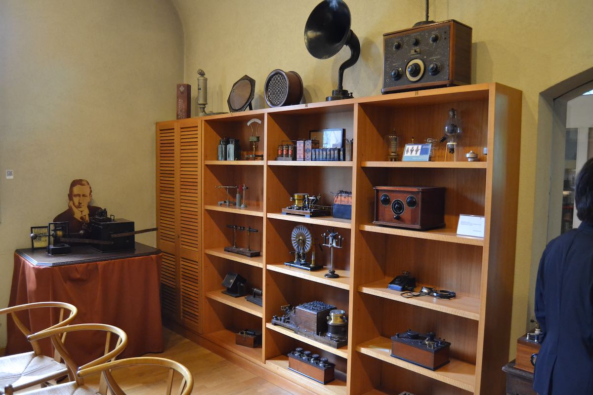
Instruments in the educational laboratory

With passion and competence, Mr. Neri explained us in a simple way (there were some very interested young people in the group) the cable telegraphy principles and the sequence of experiments and discoveries that led Marconi to his inventions.

In a detailed and fascinating exposition we saw applications of a Morse writer, the induction coil, the coherer and the first Marconi spark transmitter, all assembled in the end to transmit in the room some morse signals in the air.
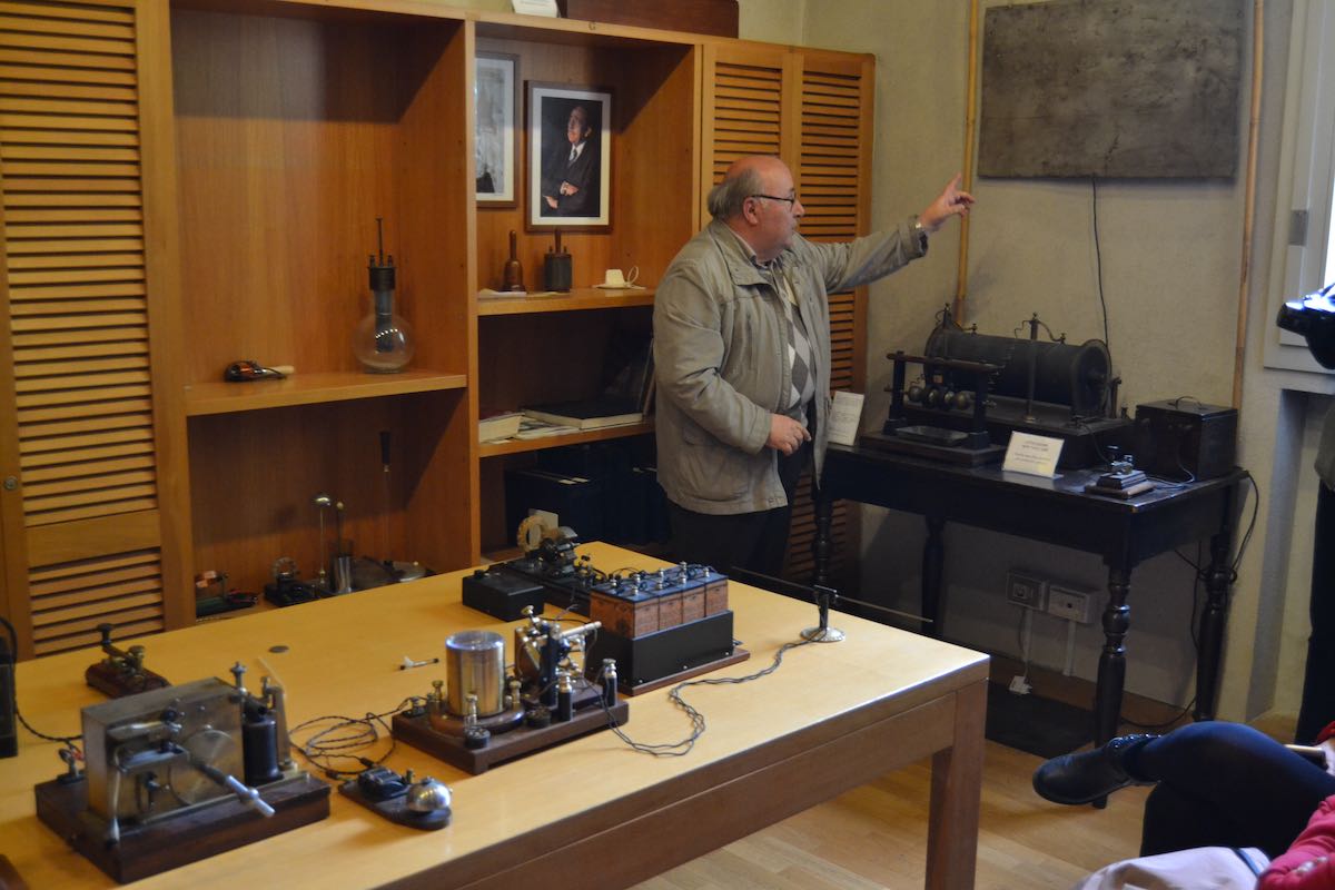
Live demonstration of signal transmission by Adriano Neri . Against the wall a Marconi spark transmitter (note the antenna and ground plates), on the table: a Marconi receiver (with a coherer) connected with a Morse writer.

The laboratory, as the whole museum, hosts a huge number of working replicas (a wonderful collection in itself, handmade by Maurizio Bigazzi with rigorous standards of adherence to the original designs and, if possible, reuse of original parts) and some original equipment.
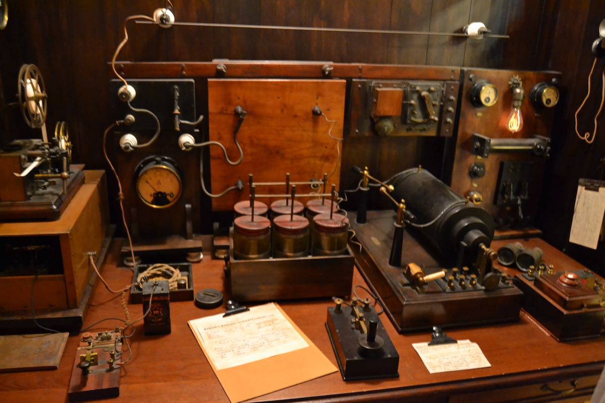
Ship wireless telegraph room – working replica

A last section of the museum is devoted to radio communication during the war (showing a WWI airplane-ground communication system) and radio broadcasting, with original sets of great interest like a 1923 Marconiphone (still working, we had a live demonstration receiving RAI programs) and a Ducati radio (the same Ducati company of motorbikes, based in Bologna).

WWI plane radio and ground receiver
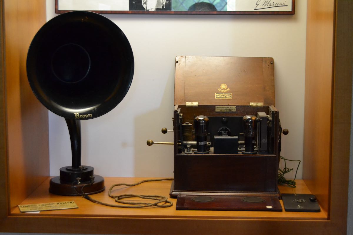
1923 Marconiphone, working original set

Ducati radio

We spent all the morning in the Museum with great fun and interest from all the family.

I highly recommend a visit to the Museum for the place,  its significance in the history of radio transmission and the competent and passionate exposition of the historical and technical themes related to Guglielmo Marconi.

A wealth of information (also in english) can be found of the Guglielmo Marconi Foundation website (www.fgm.it).

A detailed gallery of the Museum can also be found on the new Museum website (www.museomarconi.it)
Spread the radio love

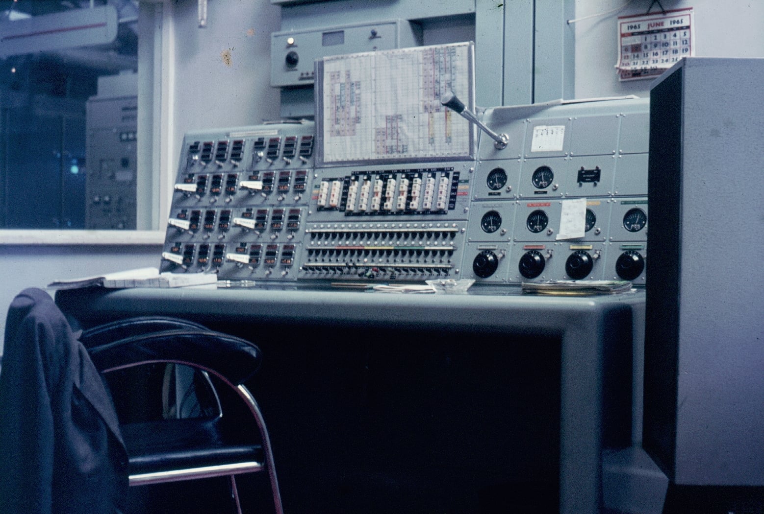
Woofferton Control Desk circa 1965

Many thanks to SWLing Post contributor, Dave Porter (G4OYX), who writes:

Thought you might like to post this pic (above) just in from Phil Brooks who used to be an engineer at Woofferton.

In front of the operator on the desk is what was described as “The External Services Operational Schedule”.

The WOF version was chopped into three eight hour periods. Where there is print the senders are ON. There are eight vertical columns and they correspond to Sender 91 to Sender 96. There are two blank columns on the RHS corresponding to Sender 85 and Sender 86 that were available but not scheduled.

Assuming that they chopped the schedule from midnight to 0800, 0800 to 1600 and 1600 to midnight then it appears that VoA services start up at 0100 and run through to 0630.

Similarly for end of night shift there is BBC starting at 0730 to cover for the maintenance break at Daventry and off at 0900. VoA resumes at 1300 and carries on until 2330 throughout day and evening shift.

WOF has a maintenance break 0900 to 1300.

The six “white flags”are the “Crater keys” and are an interlock device such that if the key is removed then the sender associated with it can’t be powered so that antenna switching can take place.

The view from the window shows part of Sender 92 in the actual sender hall.

The six Peak Programme Meters PPM (UK version of VU – but much better) show the audio on the sender output or input if selected.

This desk ran from 1963 to 1981. It was replaced when automation with a Control System (the WATCH) was installed. That ran from 1981 to 2008.

Thanks so much for sharing this, Dave. We always appreciate the context you add with a career in transmitting informing you!

Spread the radio love

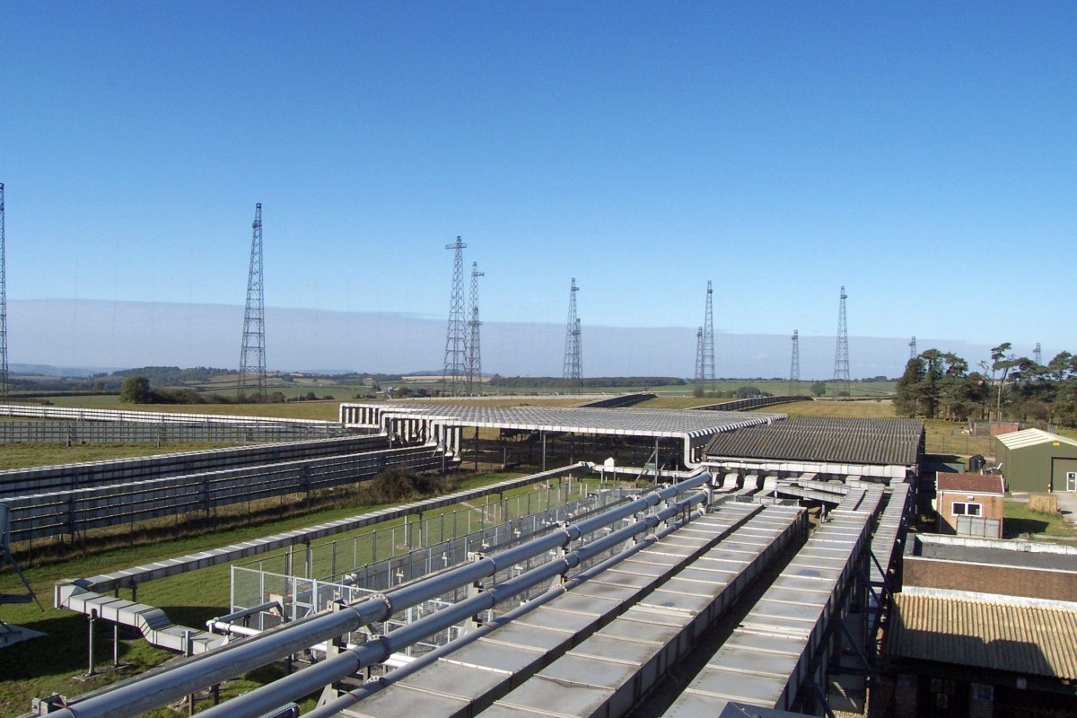
Photo gallery of the Rampisham Down transmitting site in 2003

Many thanks to SWLing Post contributor, Dave Porter, who shares a link to the following site which contains an extensive galley of photos taken at the Rampisham HF transmitting site on October 11, 2003.

Click here to view the gallery.

Thank you for the tip, Dave!

Spread the radio love

The RX888 SDR – Up Close Photos

I received my new RX888 SDR receiver today, via DHL shipping in only seven days from ordering on Ebay from seller “shenglongsi”. I’ve noticed that some Chinese Ebay sellers use a placeholder shipping number when choosing the DHL carrier, and then some days later they forward the actual shipping number when the product is out the door.  That was the case with the RX888– four days in limbo, and then BINGO!–a real tracking number was sent and the package arrived three days later.

It should be noted right up front, as others have pointed out, the RX666 and RX888 SDRs are commercial implementations of the excellent, open source BBRF103 receiver. The BBRF103 is the creation of talented Italian designer Oscar Steila IK1XPV.

Hopefully tonight I’ll be sorting out files to get the radio operating, and if there are hiccups along the way I have help from some other early adopters around the globe.

The radio arrived with zero documentation or links to support files, but I already have files known to work with the RX666. The receiver should work with HDSDR after the correct additional files are added to the HDSDR folder, as does the similar RX666 model. Cypress USB drivers also need installation on the host computer. One concern is operating the LNA (low noise amplifier) on the RX888, which the RX666 lacks. This may take a different EXTIO .dll file than the one intended for the earlier RX666.

I’m aware of the developer of another popular SDR program who will almost certainly add support for the RX888/RX666 to his software.

I’ve read that the powerful ADC chip inside these two models is a USD ~$60-70 component (or from the same chip series) which is also found in a few commercial grade SDRs plus the newer WinRadio G33DDC & G35DDCi models. Translation? The RX666 & RX888  could turn out to be amazing performers for the price.

Below are up-close pictures of the receiver’s printed circuit board. Construction and soldering look quite good considering the USD $188 price. In my opinion the build quality appears to somewhat exceed that of the RX666, which was the first of these two units on the market.

Note that in the last photo the whitish square on the bottom of the PCB is a thick foam pad, perhaps some thermal transfer material. It is sticky-backed and placed so that it’s wedged between the bottom of the chip (ADC?) with the blue heat sink and the bottom of the case.

In the below photo, note the small LEDs with indications “PWR”, “MODE”, “OVLF”, and “MODE” (again). At the upper-right corner are two pads marked “RST” (reset?).

Guy Atkins is a Sr. Graphic Designer for T-Mobile and lives near Seattle, Washington.  He’s a regular contributor to the SWLing Post.

Spread the radio love

I should be working, but instead I’m playing radio…

Ever had one of those days where you should be catching up on work, correspondence, and projects, but instead you find yourself outside, in front of a radio and just enjoying a long listening session?

Yeah, that’s me and that’s today.

How did it all happen?

Well, this morning I dropped an RF adapter behind a shelf and, in the process, picked up my Sony ICF-5500W that was standing in the way. It felt a little light because it had no batteries inside.

Next thing I know, I’m loading the ‘5500W with C cells and heading outside.

It’s a gorgeous day, so I thought it might not be a bad idea to energize the caps in this benchmark solid-state radio and check reception outdoors. Besides, it’s a perfect way to do my bit for Social DXing, right?
The ‘5500W was performing flawlessly, so the next thing I know I’ve passed a good hour band-scanning and doing a little daytime DXing.

The ‘500W is truly a remarkable mediumwave receiver and I love the fluid “tuning experience” of the analog dial.  The audio, of course, is brilliant and perhaps that’s why I can’t let go of it (nor the Panny RF-2200).

So am I the only one playing radio today instead of doing work–? Tell me it ain’t so!  Please comment!

Spread the radio love

Radio Malaysia QSL and memories

In response to our post regarding Radio Sarawak, SWLing Post contributor, M Breyel, shares the following:

These were the shortwave frequencies RTM used in 1975. This is my QSL card for an RTM transmission originating from Penang, as received on Denver, Colorado. [Click images to enlarge.]

Most MW stations in Malaysia ceased operation after 2000. That said, a 750 kW MW station in Sabah remained operational as late as 2008, if I remember correctly. My guess is FM became more prominent thereafter.

Certainly here in peninsular Malaysia (Kuala Lumpur), particularly in 1987, we had six government FM stations. Sign-off was usually at midnight or 1 am, depending on the station. An annual license (tax) was issued for each radio owned.

Note, the QSL card [above] appears to have first been printed in 1973, judging by the smaller date printed at the bottom of the card. It was one of the few folded cards I received in my DXing years from 1967 to 1980. It features three sections, folded twice and printed on both sides. The Angkasapuri studio in Kuala Lumpur, map and flag of Malaysia, caption about the country, transmitter sites and frequencies and verification data is depicted on it.

This particular card was issued for a reception report I posted on 22 November 1975, nearly 40 years ago. Unbeknownst to me then I had picked up Radio Malaysia via Penang, according to the frequency legend (4.985 kHz) stated on the card. I assumed it was Kuala Lumpur and, more importantly, I was excited to have logged a new country to my growing list of international broadcasters.

At the time I lived in Northglenn, Colorado — a suburb north of Denver. As I recall Radio Malaysia was usually received in the early morning hours between 5 and 8 am. Reception was always weak, yet music and speech was audible despite atmospheric noise.

The receiver I used was a Zenith Trans-Oceanic H-500, a 5 valve/tube radio originally manufactured in the early 1950s. The antenna was an inverted L, elevated at over 30 feet, spanning approximately 75 feet in length.

This is a photo of Angkasapuri, the RTM Headquarters in Kuala Lumpur, as it appeared in 1987. The HQ as changed very little since then:

Interestingly, the Australian Armed Forces had a radio station based in Penang in the late 70s-early 80s.

For more on vintage QSLs from Malaysia, please refer to my blogsite.

Or see this video.

Wow–thank you for sharing your DXing experience with us! It sounds like the Zenith Trans-Oceanic H-500 served you quite well back then! What a classic set.

Post readers: Please check out M Breyer’s blog for more interesting DX and radio history.


Do you enjoy the SWLing Post?

Please consider supporting us via Patreon or our Coffee Fund!

Your support makes articles like this one possible. Thank you!

Spread the radio love