 Many thanks to SWLing Post contributor, Mike (VE3MKX), who shares the following photos from the 2023 Hamvention and the Four Days in May QRPARCI Conference.
Photo Gallery
Click to view the entire photo album–> Continue reading

Many thanks to SWLing Post contributor, Mike (VE3MKX), who shares the following photos from the 2023 Hamvention and the Four Days in May QRPARCI Conference.
Click to view the entire photo album–> Continue reading
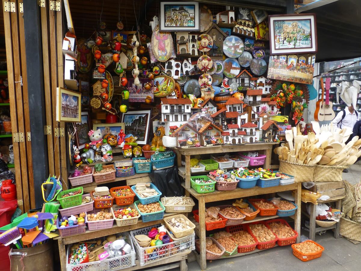
A Cuenca Artisan Market
Many thanks to SWLing Post contributor, Don Moore–noted author, traveler, and DXer–for the latest installment of his Photo Album guest post series:
by Don Moore
In the song Por Eso Te Quiero Cuenca (That’s Why I Love You Cuenca) the singer recites a litany of the many reasons to love this city. What do I love about Cuenca? Well, unlike the song, I won’t include well-roasted guinea pig.
The elevation of 2560 meters (8,400 feet) gives Cuenca a comfortable spring-like climate year-round. Daily highs are usually around 20C/70F. Nights are chilly but not cold. Most days have at least several hours of sun, even during the rainy season (as it is now). There are numerous green parks and plazas including long tree-lined walking paths along the two main rivers that run through the city. The drinking water, which comes from high up in the mountains, is the best in South America. Yes, you can drink it right from the tap.
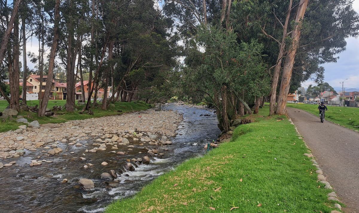
A walking/bike path runs along the Yanuncay River for over six kilometers through the south side of Cuenca. A similar path runs along the larger Tomebamba River in the center of town.
The people of Cuenca are among the friendliest I’ve found anywhere. It’s a well-run, educated city with lots of civic pride. The metro area population is only about a half-million so it’s small enough to easily get anywhere but large enough to have the benefits of a city. Cuenca has several good universities and theaters and the symphony orchestra gives free concerts most Friday evenings. It’s a pleasure to simply stroll through the beautiful architecture in the old centro neighborhood.
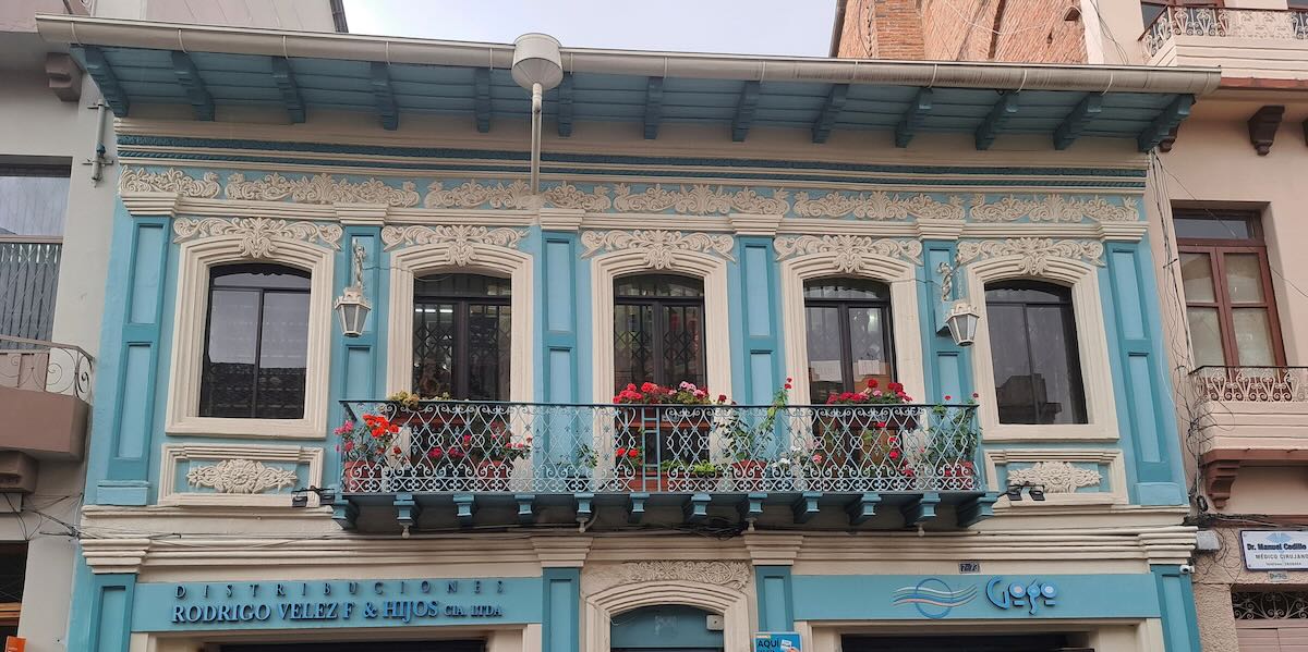
One of many beautifully restored buildings in Cuenca’s old centro.
Getting around Cuenca is easy. A ride on the excellent bus system costs just thirty cents and taxi rides usually run under two dollars. And, unlike the much larger cities of Quito and Guayaquil, Cuenca has a mass transit system. In 2013 city leaders voted to put in a light rail line. Doing so required digging up two of the main streets through the old downtown but rather than just dig up two streets they decided to dig up the entire old downtown … to replace the aging water and sewer systems, move all electric lines and cables underground, and install high-speed fiber optic Internet. (Fiber optic Internet was also run above ground in the newer neighborhoods outside the centro.) The result is one of the few places in Latin America where one can enjoy beautifully restored architecture and colonial churches without the views being marred by powerlines. And the Internet here is better than most places I’ve stayed at in the United States.
Those are just a handful of the reasons that I love Cuenca.
Radio broadcasting in Ecuador started in 1925 with Radio El Prado in Riobamba, a small city in the center of the country. Other stations soon started up in Guayaquil and Quito, including HCJB in 1931. Broadcasting came to Cuenca in 1934 when a group of friends purchased a homemade ten-watt transmitter from an engineer in Guayaquil and put it on the air as La Voz de Tomebamba. The name came from the main river flowing through Cuenca. At the time there were only four receivers in the city so the audience was rather sparse. La Voz de Tomebamba initially broadcast for only one or two hours a night and most of the musical selections were done live as there weren’t many 78 RPM records in town. Years later one early listener reminisced, “It was sixty percent noise. Only radio fanatics could be entertained by listening to such a thing.”

Old studio equipment from La Voz de Tomebamba
Gradually, the owners added new equipment and expanded the daily schedule. A fifty-watt transmitter was added in 1938 and by 1947 the power had been increased to two hundred watts. The first frequency listing that I’ve found for La Voz de Tomebamba was for 4200 kHz in a 1944 FBIS newsletter. The 1947 WRTH listed it as on the air from 0000 to 0430 GMT on 4200 kHz. And that was the station’s only frequency. Until the 1960s it was very common for radio stations in Ecuador to only broadcast on shortwave and not on medium wave. For example, the 1957 WRTH lists eighty Ecuadorian stations on shortwave (not counting HCJB) but only fifty-nine on medium wave.
Sometime in the early 1960s La Voz de Tomebamba made the switch to medium wave and left shortwave. Their 4200 kHz frequency is not listed in the 1965 WRTH, nor are they listed in any later ones. (I would be interested to hear from anyone who remembers listening to them on shortwave.) The changes may have had to do with financial problems the station was having. It closed in 1967 and remained off the air until returning under new ownership four years later. Today La Voz de Tomebamba is one of the most popular radio stations in town and has an excellent news department. Their sister station, Super Rock FM 94.9, is very popular with younger listeners.
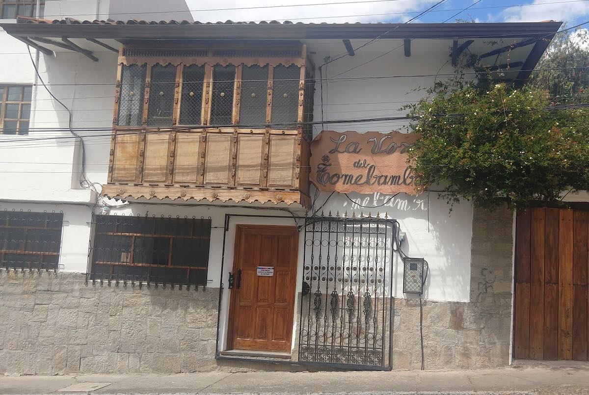
La Voz de Tomebamba today.
The second station in Cuenca was Radio Cuenca, which began broadcasting in October 1945 on 2830 kHz with two-hundred watts. It was included in a 1953 list of stations logged by the Universal Radio DX Club of Indiana. To the local audience, Radio Cuenca was best known for its many live music broadcasts. Continue reading
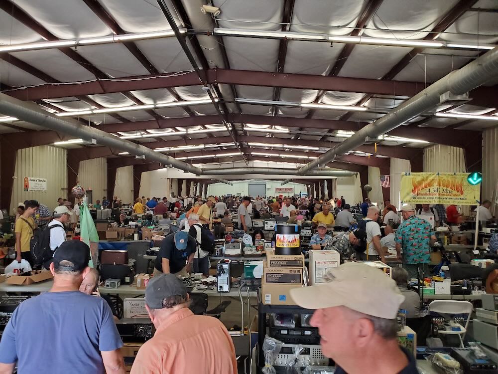 Many thanks to SWLing Post contributor, Mike (VE3MKX), for sharing over 100 photos from the 2023 Hamcation, the majority of which are from the flea market. If you would like to view this gallery of photos, click the link below:
 Many thanks to SWLing Post contributor, Pavel, who shares the following message and images. Note that this message was originally sent to me prior to Christmas, but never arrived in my inbox. Thank you, Pavel, for the follow-up:
Hi Thomas,
First of all, I wish you and your entire family and all blog readers a wonderful rest of the Christmas holidays, all the best for the new year 2023, lots of health and well-being and many beautiful moments listening to the radio.
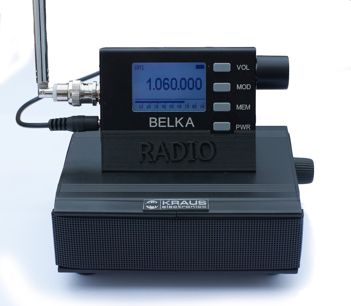
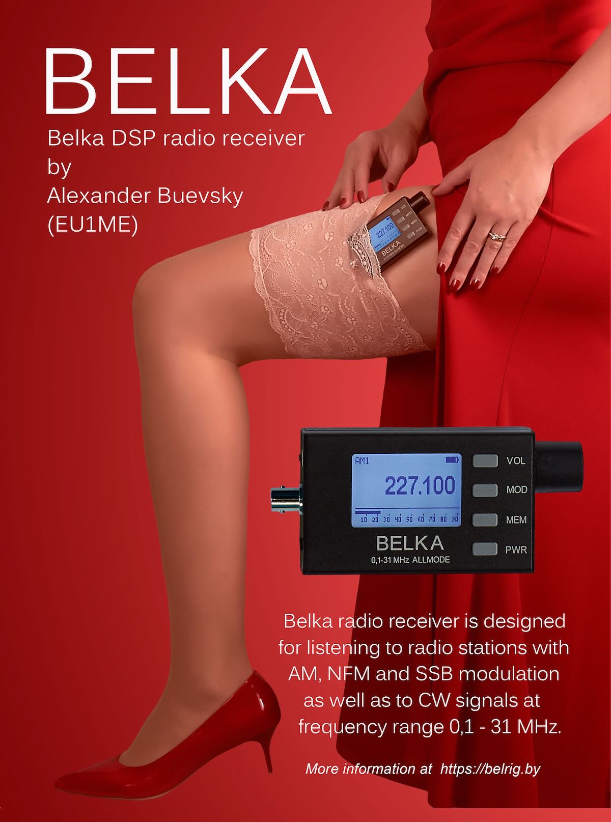
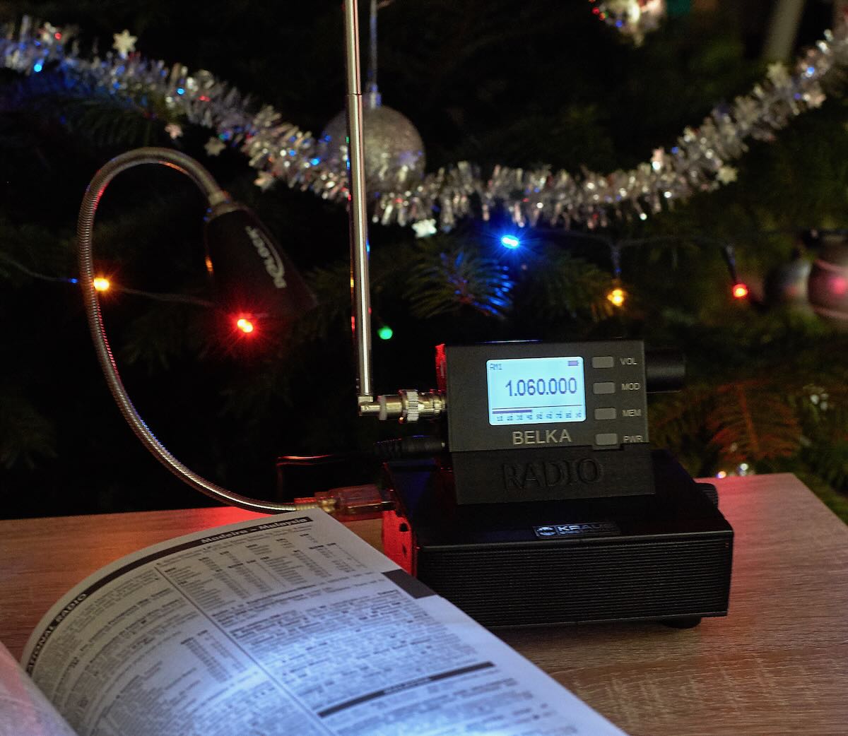
Some time ago I became the owner of the last type of Belky. I’m excited about her. So I immediately made an advertising poster with my wife and Belka :-).
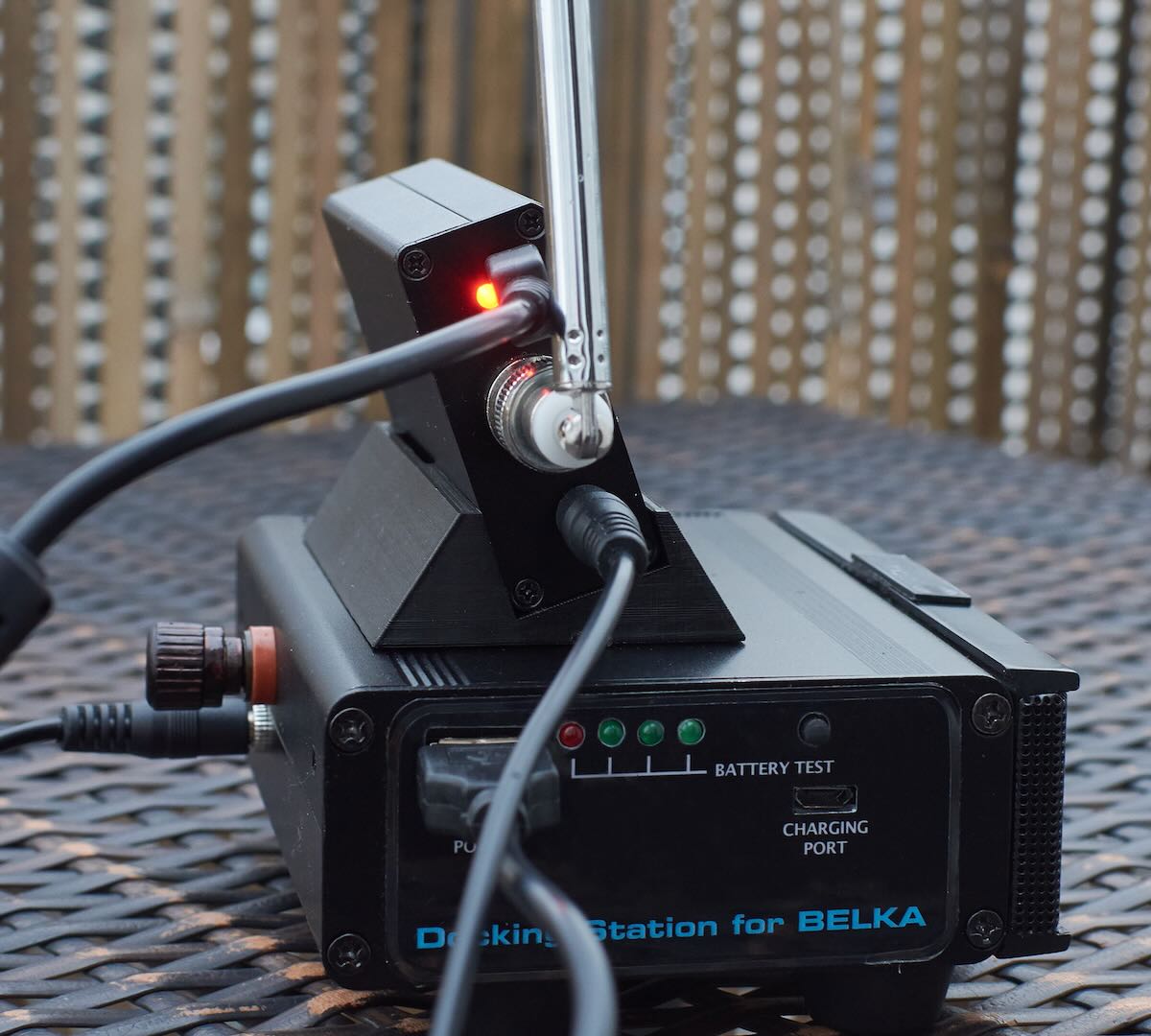
I made a small docking station for the Belka – it has a built-in stereo amplifier, speakers and a battery with a charging circuit and a Dc-Dc converter for emergency charging of the Belka in the field. The status of the battery is indicated by LEDs. The Belka holder itself is made on a 3D printer.
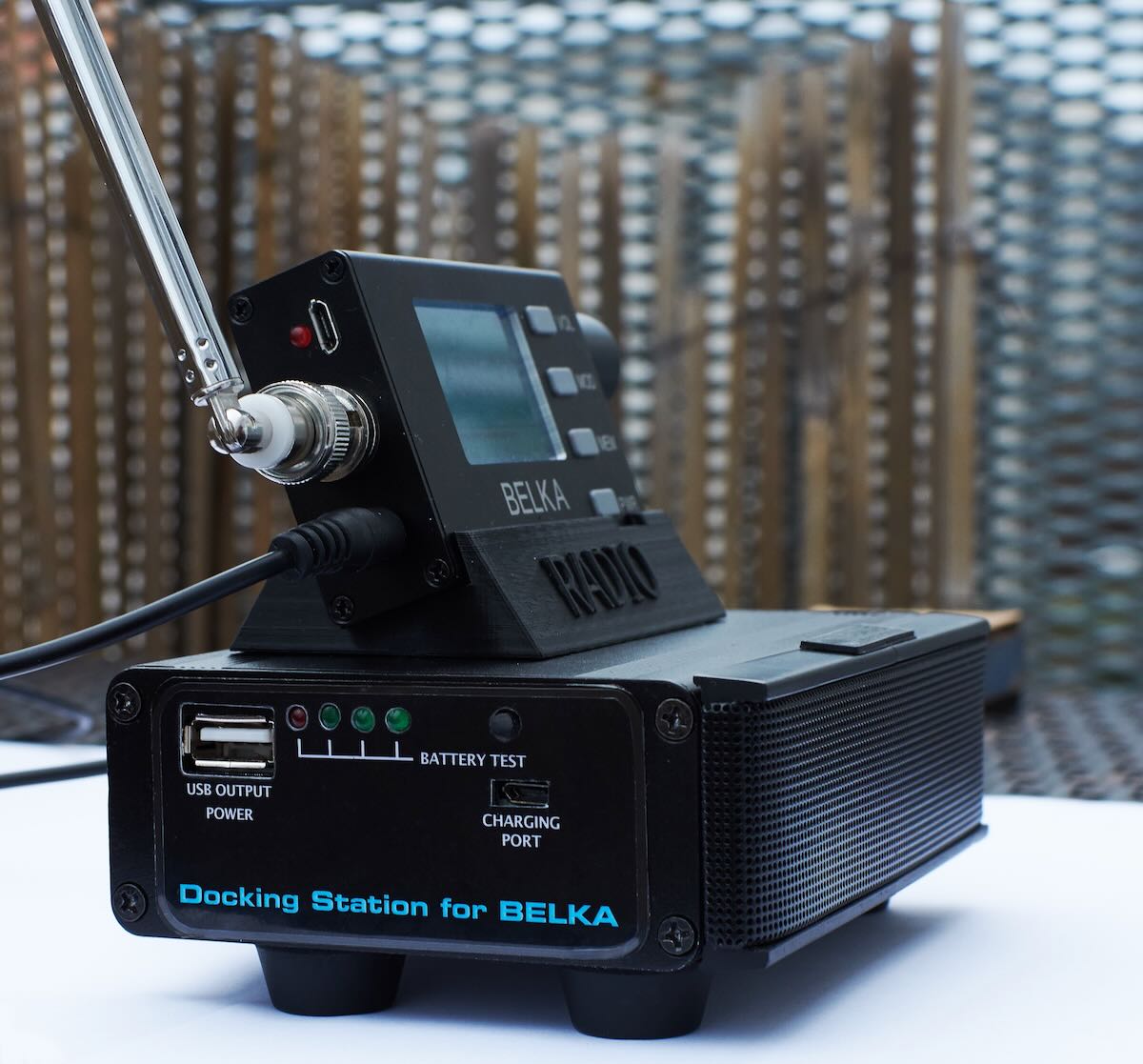
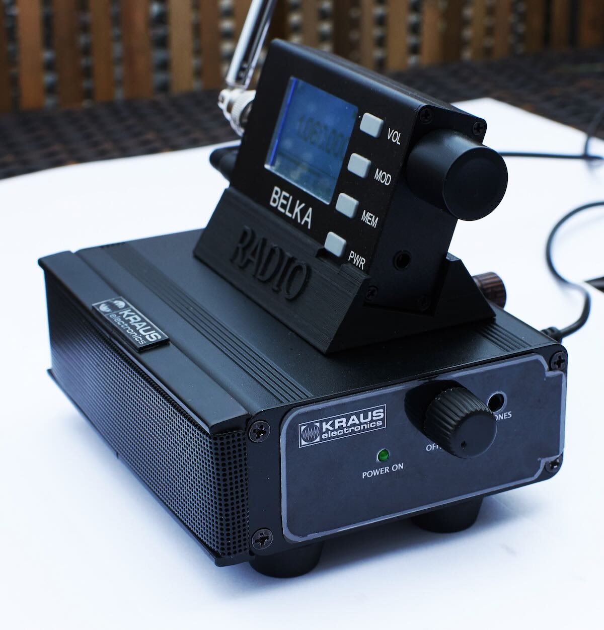

Maybe it can serve as inspiration for blog readers.
Hi
Pavel Kraus
Thank you for sharing this, Pavel. We all love both your creativity not only in your photos, but the amazing radios you produce. We love how you use your wife as your model in your work!
 Many thanks to SWLing Post contributor, Balázs Kovács, who writes:
Hi Thomas,
Happy New Year! Some pictures in two topics:
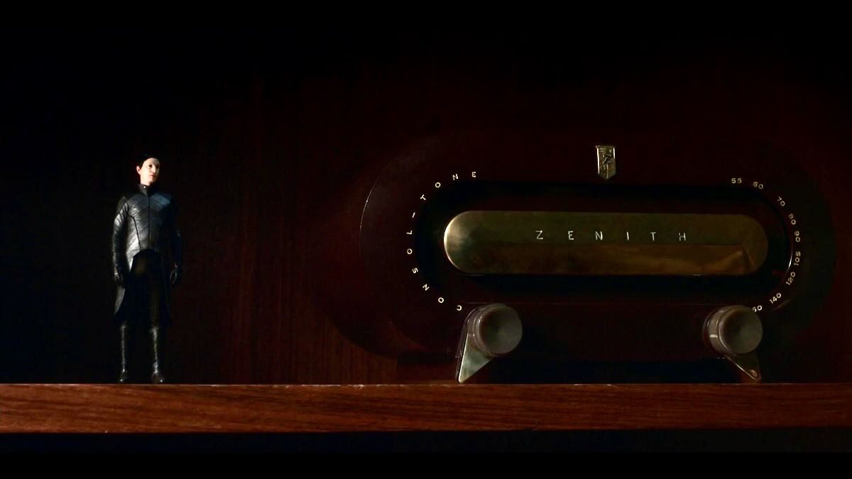
1.) First, a nice Zenith H511 Consoltone (MW) got a few seconds of screen time recently in the fourth episode of the third (final) season of “His Dark Materials” series:
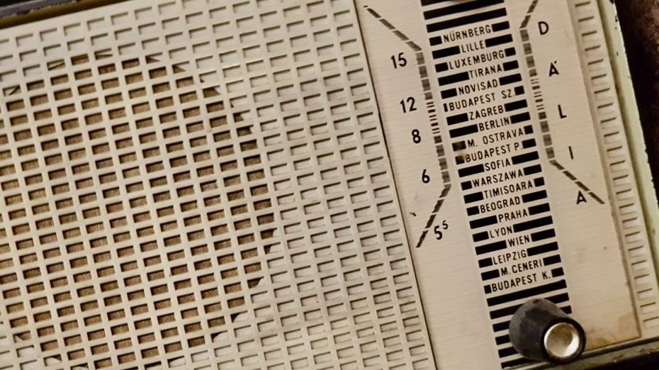
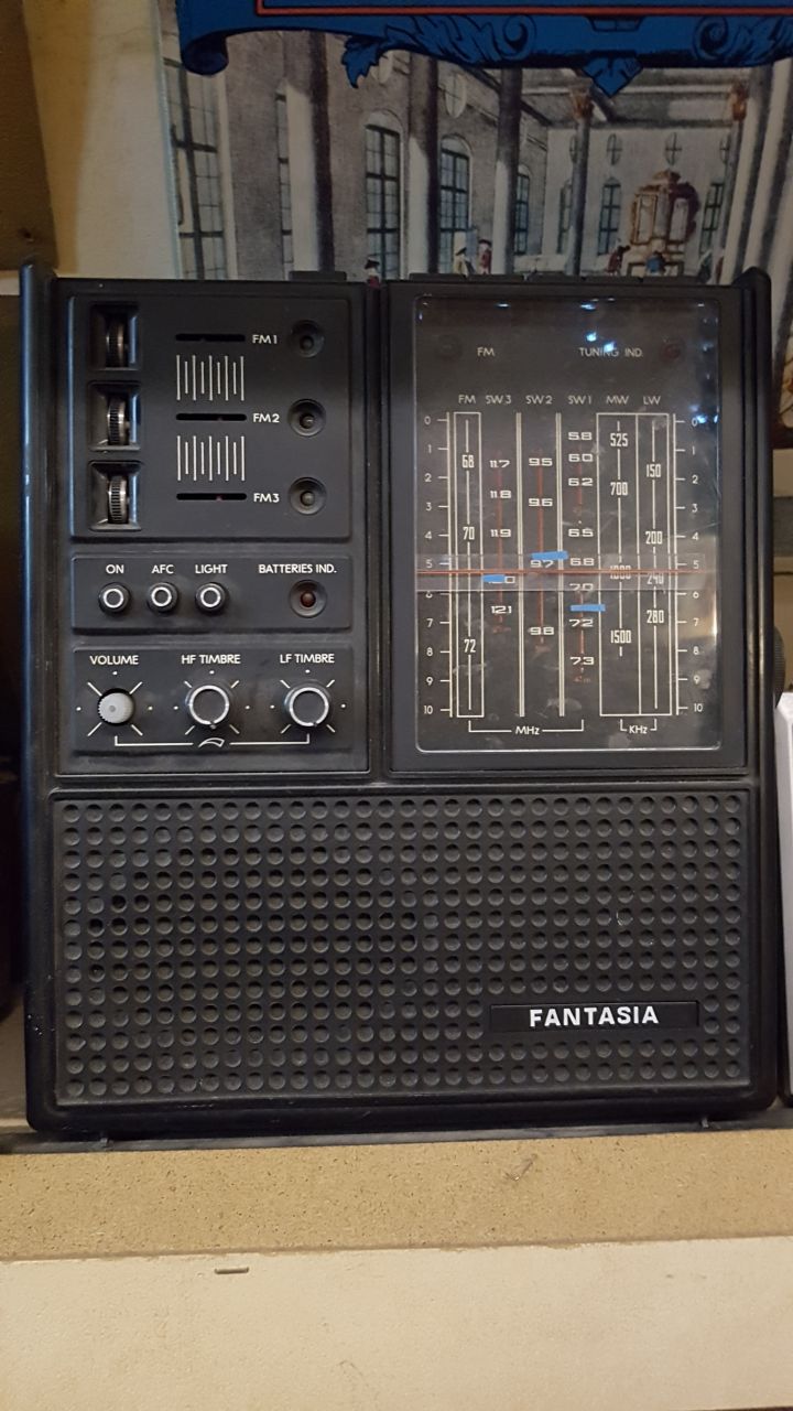
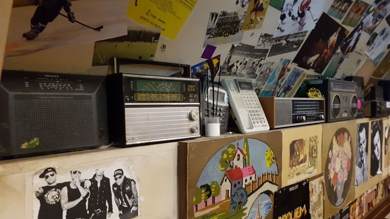
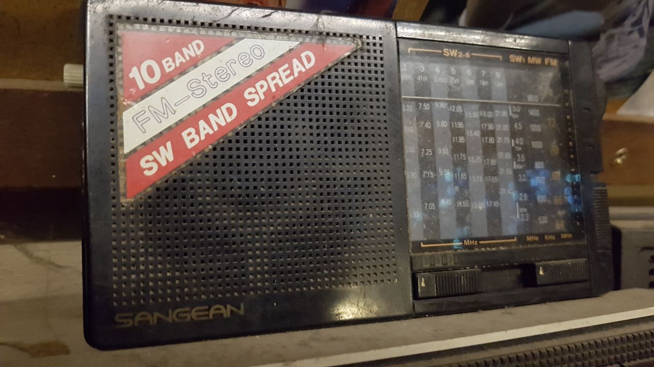
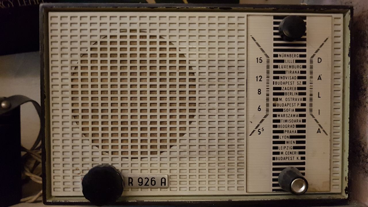
2.) At the end of December in an old pub in Budapest (Helvecia) I ran into some more or less old radios as a part of the eclectic decoration. Since these are partly Eastern European, they may be less well known elsewhere (deep in the basement, so even if they were still functioning, not many radio signals would reach them anymore):

With best regards,
Balazs
Wow! I love those pub radios! I especially love the dial markings on the R 926 A!
Thank you for sharing these images, Balazs!
Many thanks to SWLing Post contributor, Don Moore–noted author, traveler, and DXer–for the following Photo Album guest post series:
 Don Moore’s Photo Album: Santa Bárbara, Honduras
by Don Moore
I first set foot in Latin America in January 1982 when I arrived in Tegucigalpa to begin three months of Peace Corps training. Three months later I moved to my Honduran home, the town of Santa Bárbara in the western mountains. For the next two years I worked as a teacher and resource person at the Escuela Normal Mixta de Santa Bárbara, a specialized high school that trained its students to teach primary school.
Santa Bárbara had a shortwave station, La Voz del Junco on 6075 kHz but it was rarely reported because it broadcast irregularly and was usually blocked by big international broadcasters when it was on the air. I had never heard it but I met Miguel Hasbun, the owner-manager, on my first visit to Santa Bárbara when he picked me up hitchhiking north of town. He told me that the shortwave transmitter had been broken down for a while but that he was going to fix it ‘soon’. Over the next year I kept inquiring about the shortwave and he finally did fix it. After that the station broadcast irregularly for the next year or so, mostly in the morning. I served as volunteer veri-signer and issued around fifteen QSLs. I even issued one to myself.
Santa Bárbara had one other radio station, Ondas del Ulúa on 1140 kHz medium wave (later 1150 kHz). They also announced 4770 kHz shortwave in their canned IDs and station staff assured me they would be adding shortwave “soon”. It never did happen but the WRTH did list the frequency as future plans for several years.
Ondas del Ulúa 1982 sign-off announcement mentioning 4770 kHz.
The department of Santa Bárbara had one other radio station, Radio Luz y Vida on 1600 and 3250 kHz in the town of San Luis. The founder, manager, and veri-signer for Radio Luz y Vida was a missionary from Oklahoma named Don Moore. Needless to say, this caused a lot of confusion in the DX world as some people assumed he and I were the same person. On the map, San Luis is only about thirty kilometers from Santa Bárbara but getting there involved a five-hour journey on two buses. I only went once and the other Don Moore was out of town, so I never met him. I did meet two nurses who were working at the mission’s health clinic.
These pictures were all taken in 1982 to 1984 while I lived in Santa Bárbara [click on photos to enlarge].
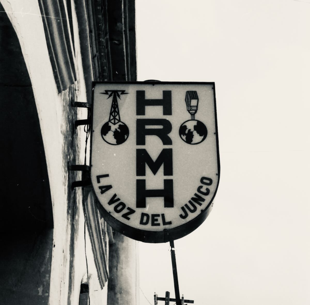
La Voz del Junco’s yellow sign on main street in downtown Santa Bárbara. The small tower on the left was the corner of what had been an army post but was being used as a regional prison in the early 1980s. I once went there every day for a week to supervise student-teachers doing adult literacy classes for the inmates. It was not a pleasant place to be.
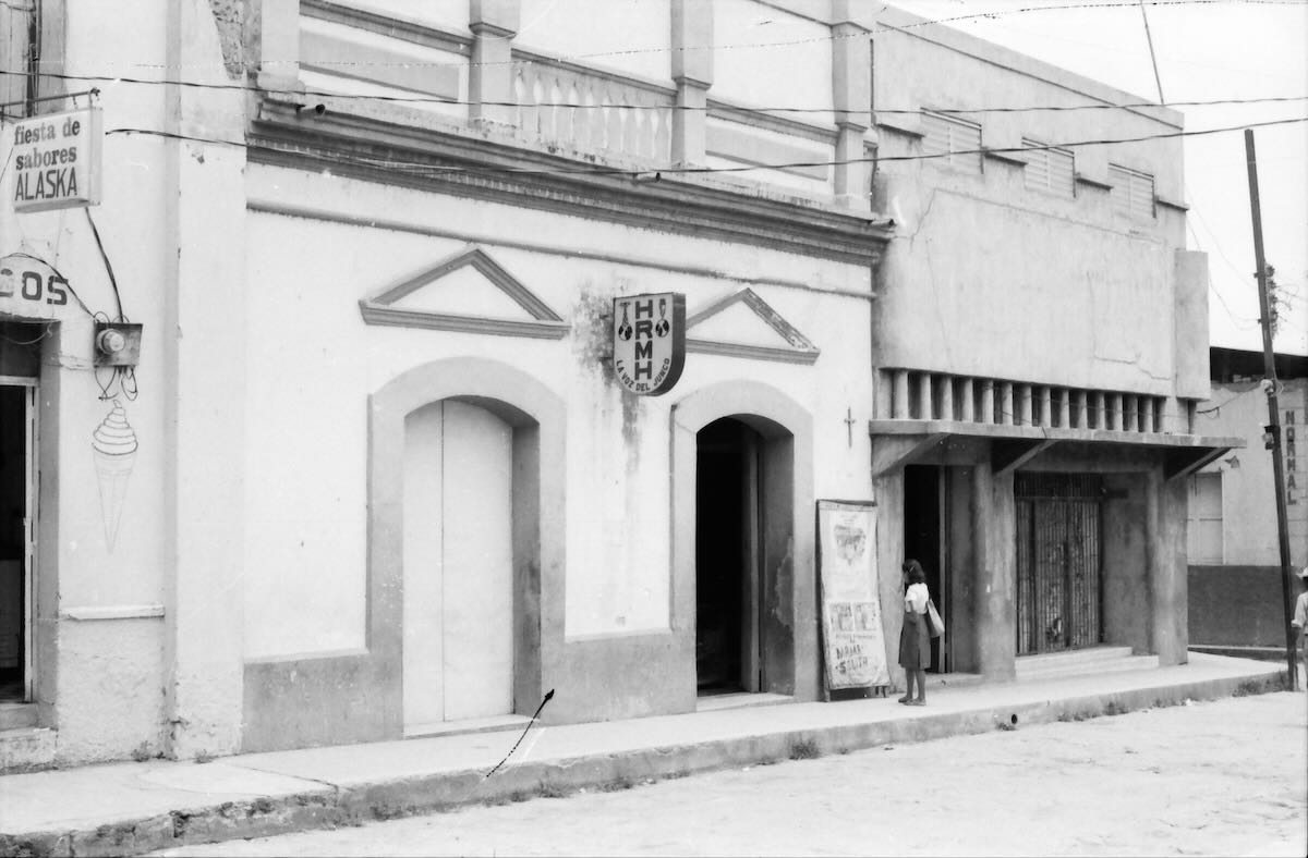
Entrance to La Voz del Junco. The girl is examining a poster for the night’s showing at the makeshift movie theater that Don Miguel operated nearby. Continue reading
Many thanks to SWLing Post contributor, Don Moore–noted author, traveler, and DXer–for the following guest post series:
by Don Moore
When I discovered DXing over fifty years ago I also discovered the world. Through my ears I traveled to other countries and explored other cultures. But DXing has also literally taken me places. My early interest in Latin American DXing developed into a broader interest in Latin America. That led to me joining the Peace Corps after college and working three years in Honduras. That experience furthered my interest in Latin America and I have continued to travel in the region whenever possible. For me DXing and travel were always intertwined. I’m one of a handful of hobbyists who took DXing beyond just listening and went knocking on broadcasters’ doors to visit the distant stations I heard. My ex-wife dubbed this ‘door-to-door DXing.’
To date I’ve visited over 150 radio stations in thirteen countries. A few were medium-wave or FM only, but I was always most interested in visiting broadcasters that used shortwave, either at the time of my visit or a few years before. As my station visits were primarily made in the 1980s and 1990s, almost all of the stations are long-gone from the shortwave bands. However, many are still around on medium wave and FM and often also via streaming on the Internet. As much as I miss the magic of shortwave I know that these stations reach more listeners today via streaming than they ever did with their low-powered shortwave transmitters. Honestly, I sometimes enjoy tuning them in without the fading and static of shortwave. But the memories of what shortwave once was are still there.
Photos also bring back memories. I took dozens of pictures on my station visits and enjoy scrolling through them now and then. You may have seen some of them. Many of my photos were printed with articles I wrote for various DX publications and I’ve done a few slide-shows at DX get-togethers over the years.
In this series of columns I want to share my old photos once again. If you’ve been DXing as long as I have maybe they’ll bring back memories of what you once heard. And if you haven’t been around that long you will have a better understanding of the good old days we oldtimers talk about.
There is no better place to start this journey than with Ecos del Torbes. Using ten kilowatts on 4980 kHz, this Venezuelan broadcaster was possibly the most consistent station in the sixty-meter band throughout the 1970s, 80s, and 90s. If you were DXing the tropical bands during those years you surely logged them a few times. If you were lucky you may even have heard their one kilowatt signal on 9640 kHz. They were a very good verifier and for many DXers Ecos del Torbes was among the first Latin American stations QSLed.
Just after Christmas in 1994, my then-wife, four-year-old daughter, and I flew to Mérida in western Venezuela for a family vacation. For ten days we had a great time in this Andean city and then Theresa and Rebecca returned to Iowa while I stayed another week to visit radio stations. I was also getting paid by the Voice of America to research and write a study on the media scene in Andean Venezuela. The now very-out-of-date report can be read at my Patepluma Radio website (which hasn’t been changed in over twenty years and is in need of a facelift).
In that week I visited fifteen radio stations in six towns and cities and Ecos del Torbes was the highlight. I arrived at their doorstep unannounced but was immediately treated as an important guest. I was given a great tour and even got to sit in on a live newscast to see the famous Venezuelan doorbell being used live. I was there about ninety minutes and then walked a block up the street to sister station Radio Táchira. Their facilities were smaller but that’s where the technical offices were and Chief Engineer Ivan Escobar had been told to expect me. Ivan gave me a tour and invited me to visit the Ecos del Torbes transmitter site with him in the afternoon. On the way we stopped by his house where his wife had lunch waiting for us. Visiting Ecos del Torbes was not just the highlight of this trip but ranks as one of my all-time favorite station visits. These pictures bring back many good memories.
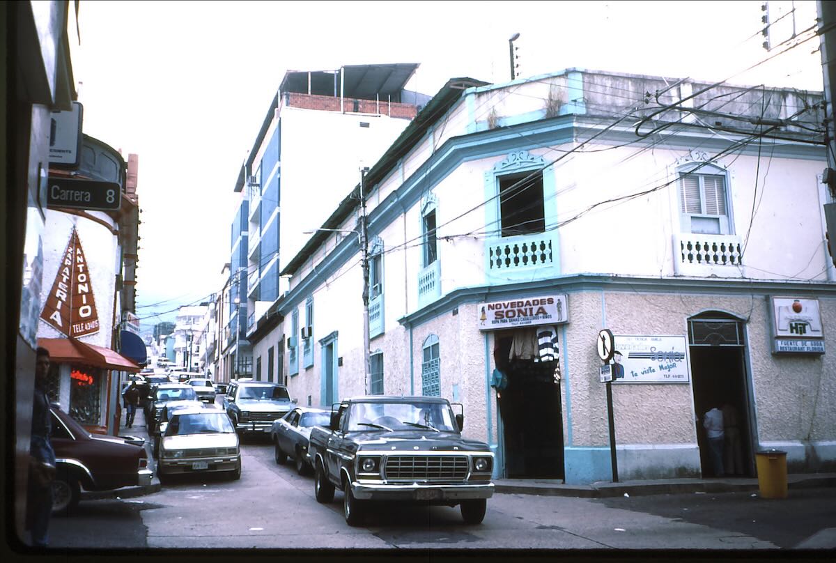
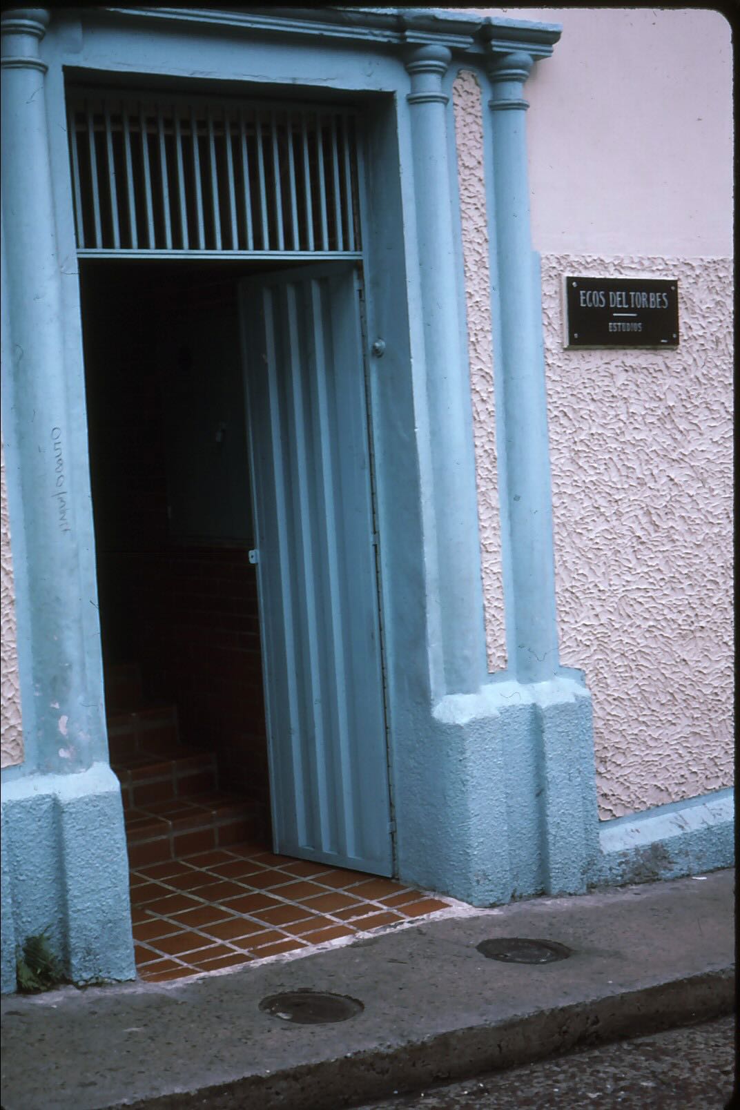
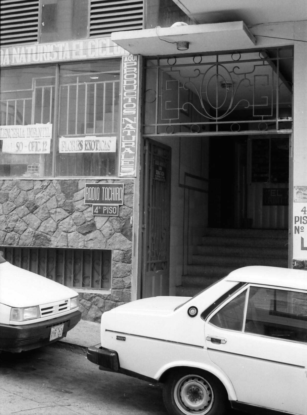
Ecos del Torbes was located in the second floor of this building in downtown San Cristóbal. The entrance was the door on the side.
The small plaque next to the door was easy to miss. I walked right by the first time.
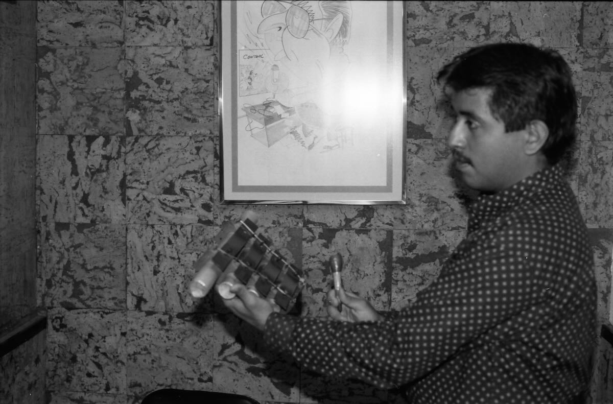
Edgar Fabala of the news department showed me around. Here he demonstrates the mini-xylophones that Venezuelan stations used to make the distinctive ‘doorbell’ sound that separated items in the news reports.
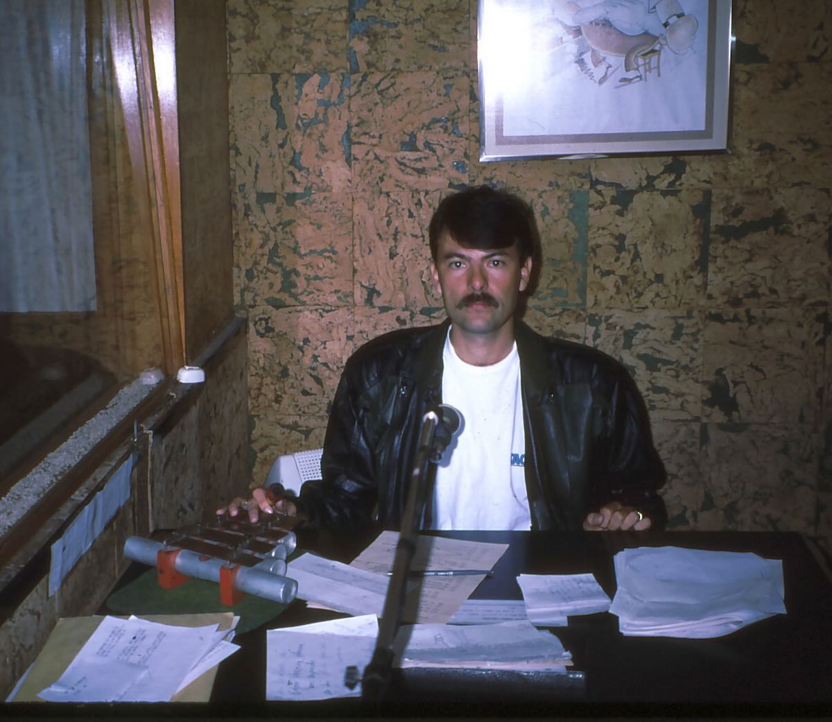
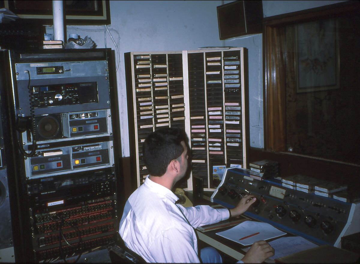
Announcer in the studio preparing to read the news.
The adjoining control room.
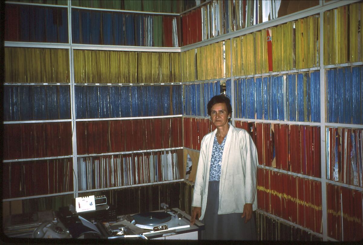
Ecos del Torbes had one of the largest record libraries in Venezuela. The LPs were color-coded by type.
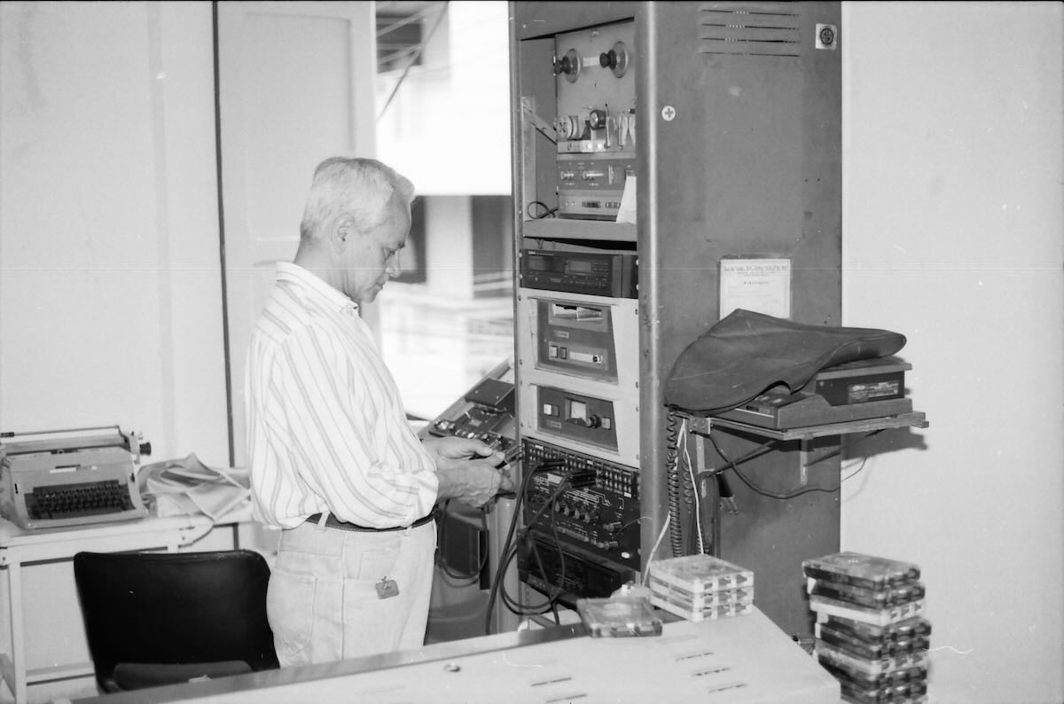
Julio Achila was a control room operator who had worked at the station since it opened in 1947.
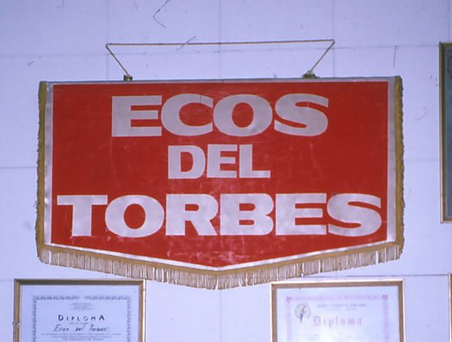
This pennant was considerably larger than the ones sent to DXers.
Sister station Radio Táchira was located a block up the street on the fourth floor of this building.
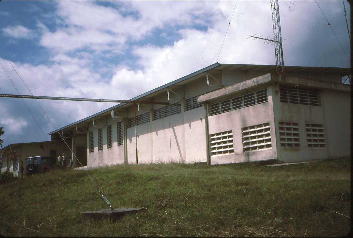
The Ecos del Torbes transmitter building.
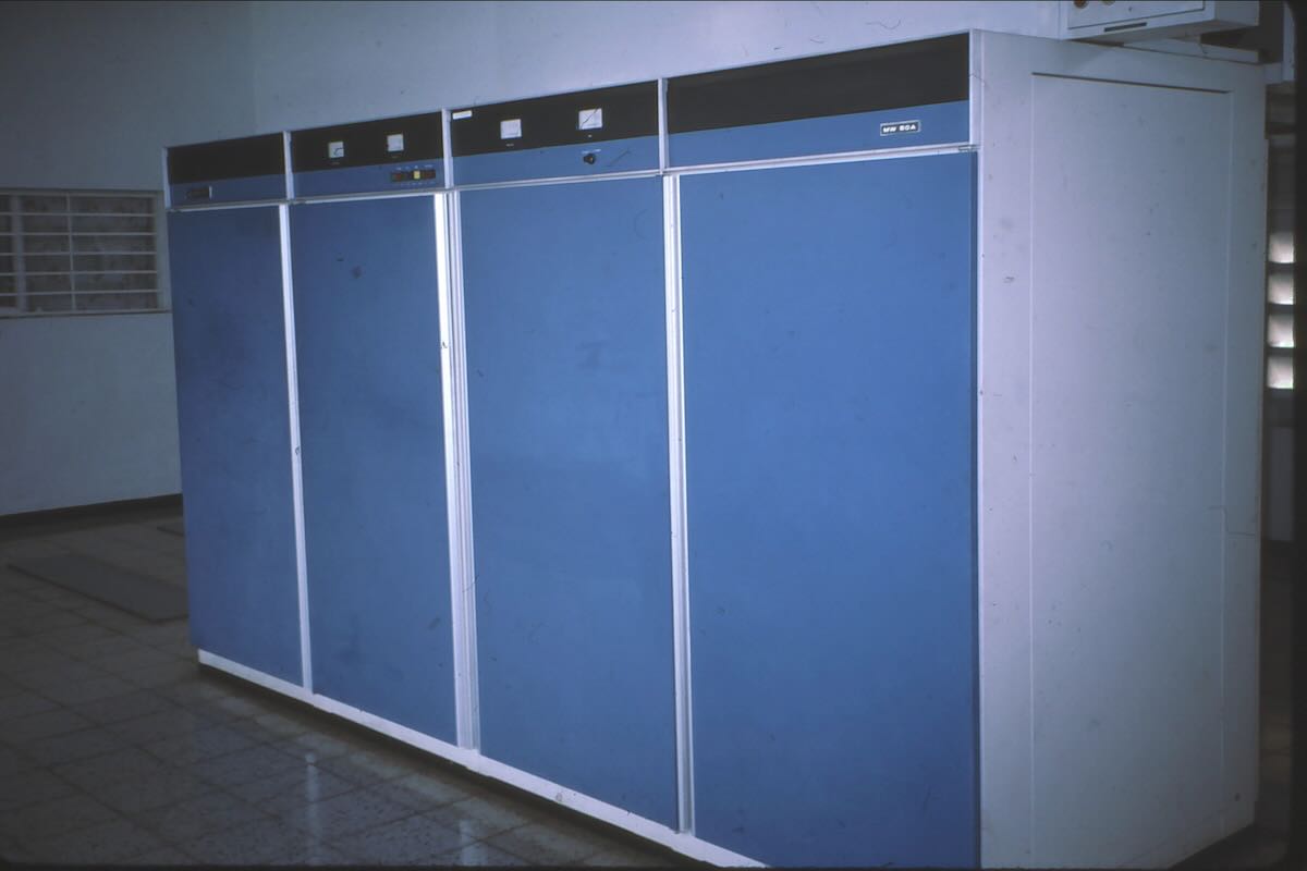
The 50 kilowatt medium wave transmitter on 780 kHz.
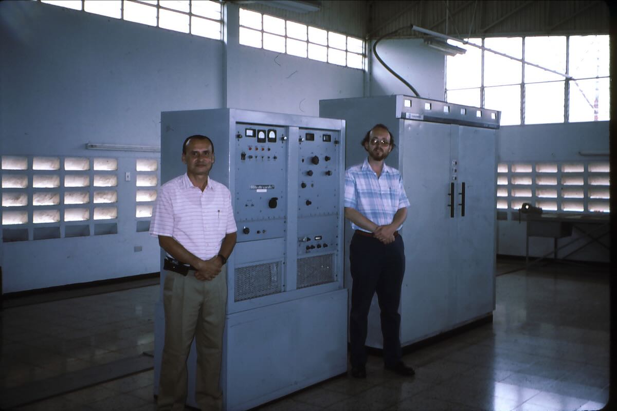
Chief Engineer Ivan Escobar and Don Moore next to the 31 meter transmitter. The larger transmitter was for the well-heard 4980 kHz frequency.
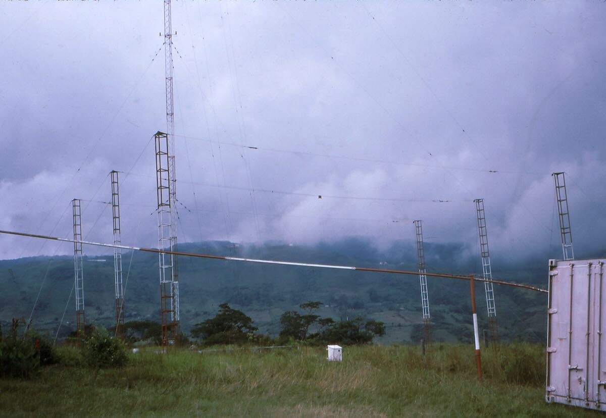
The antenna array used for 4980 kHz. The medium wave tower is in the background.
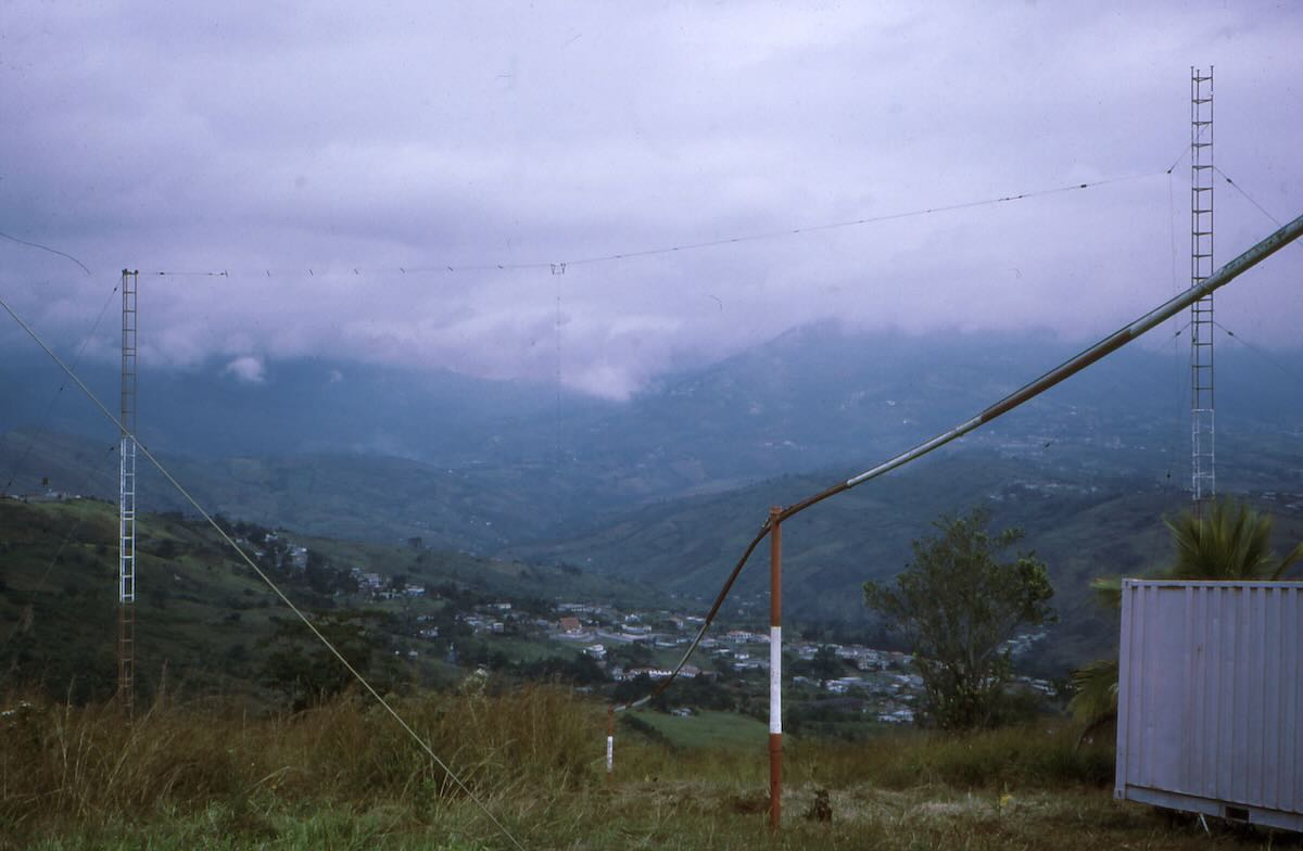
Dipole antenna used for 9640 kHz.
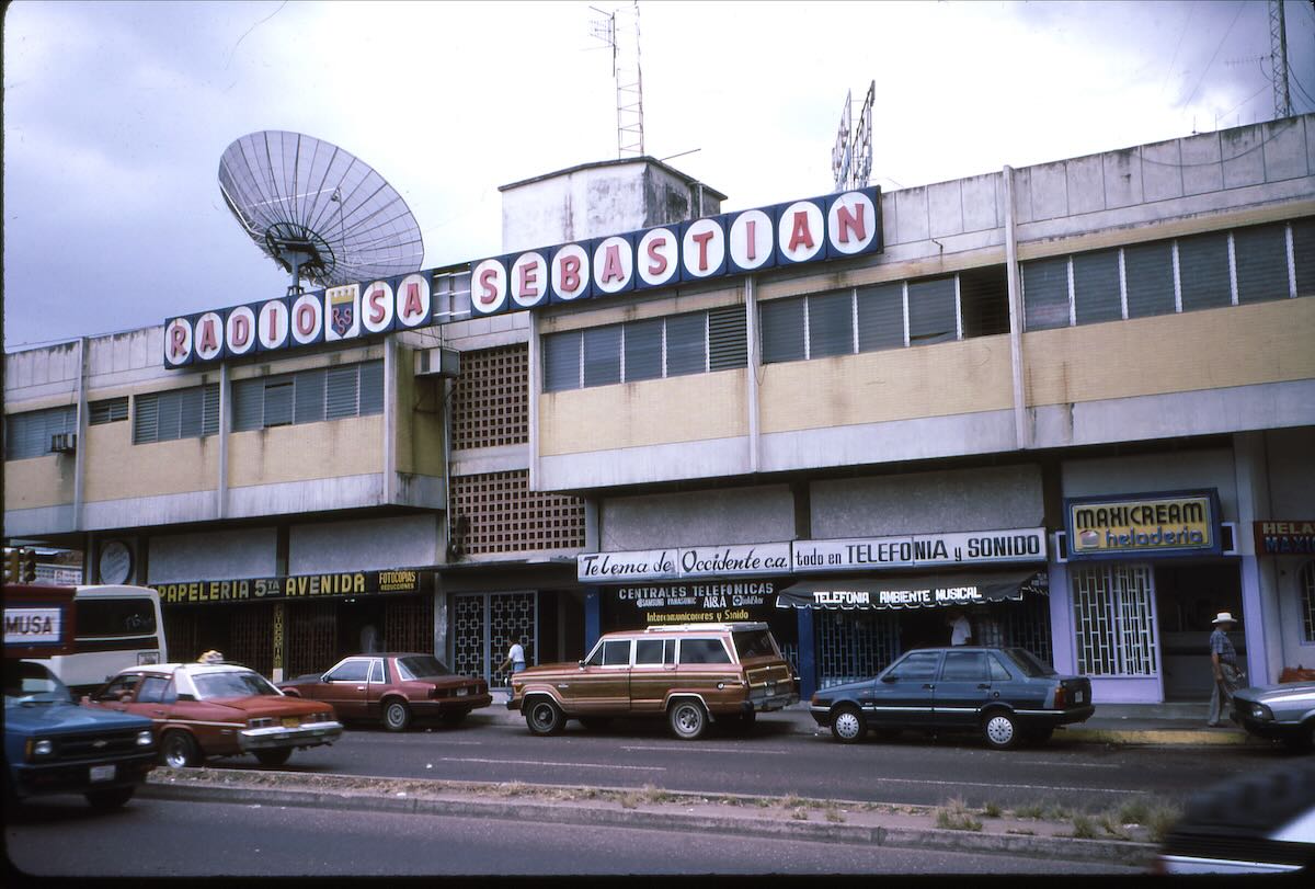
San Cristóbal once had a third broadcaster on shortwave. Radio San Sebastian used 6070 kHz in the early 1970s. (They were not affiliated with Ecos del Torbes).
That was nearly three decades ago and a lot has changed. Ecos del Torbes and Radio Táchira have been gone from shortwave for over twenty years.
In 1995 Ecos del Torbes was at the corner of Calle 9 and Carrera 8, the same address as when I first QSLed them in 1972. Sometime since my visit they moved an outer neighborhood about two kilometers to the east. To find the new offices locate San Cristóbal on Google maps and then search for “Grupo Radial Gonzalez Lovera”. The transmitter site is still where I visited it and can be seen by plugging the coordinates “7.7885, -72.2725” into Google maps and switching to satellite view. (Ignore the picture that pops up to the side. That’s not it.) Zooming in, the medium wave tower is clearly visible but there are no signs of the old shortwave antennas. I suspect they were sold for scrap years ago. I never have found out where the Radio Táchira transmitter site was.
I’d love to go back to Venezuela someday and see some of the other cities that I used to listen to, such as Barquisimeto, Valencia, El Tigre, and Sucre. Unfortunately the political and economic situation there doesn’t look good and it doesn’t look as if it will improve any time soon. But when it does, I’ll be back.