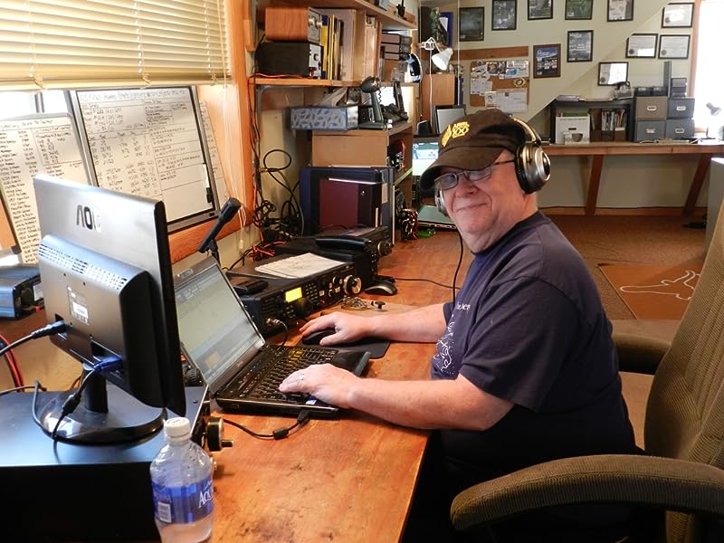
Jock gets a good grounding!

Many thanks to SWLing Post contributor, Jock Elliott, who shares the following guest post:


Getting grounded – at last!

By Jock Elliott, KB2GOM

Readers’ comments are among the best things about writing for the SWLing.com blog. When a reader responds to a post and leaves a comment, it does three things. First, it lets the author know that someone actually read the post. Second, it provides valuable feedback – “I liked it.” “Did you know about this . . .?” “I had a similar experience.” – and so forth. Finally, it provides the author an opportunity to learn something, and that perhaps is the most fun.

A case in point: when I posted this, Andrew (grayhat) said:

“If you want to make an experiment, connect the end-fed to the Satellit high-Z wire input (clamp), then pick a (relatively short) run of insulated wire connect one end of the wire to the high-Z “ground” (clamp) and the other end of that wire to the “gnd” hole in the wall plug

The above being said, I prefer keeping antennas outside and taking care of the feedline, this helps reducing or eliminating noise from indoor appliances like switching PSUs and other things, anyway, if you want, try the above idea and let me know how it works for you”

To which, I responded:

“Thanks for the comments.

Thanks to a tree falling on the powerlines, I now know that the inherent electrical noise in my radio room is basically down to the level of atmospheric noise.

Neverthless, experimenting with a ground is definitely worth trying. A thin wire, sneaked out the window to a ground rod, might do the trick. I’ll report back after I try.”

Andrew (grayhat) came back to me and said:

“I was serious, try the “wall plug ground” I described, it won’t start any “magic smoke” or the like, otherwise, if you can lay out a wire with a length of 5m max, cut to be NON resonant, and connected to a good ground stake, go for it

Then, if you want to discuss this further, just ask Thomas for my e-mail, I agree to share it with you.”

Now, I really appreciated Andrew’s comments, but what I had not told him was that there is just one wall plug in my radio shack; it is really inaccessible, and I am not sure I can get a ground off it. Further, the rest of the power “system” in my shack is a rat’s nest of power bars and extensions, and I have zero confidence that any of them will provide a useful ground.

But – and this is a big but – I did take Andrew’s point: that connecting an actual ground to the ground clip on the back of the Satellit 800 might improve things. Continue reading

Spread the radio love

2022 W9IMS Special Event Station Details!

W9IMS Special Event No. 1: The 2022 Certificate Chase Begins

By Brian D. Smith, W9IND

A journey of a thousand miles begins with a single step, as the proverb goes, and the road to a 2022 W9IMS Checkered Flag Award begins with a single QSO – or a single SWL reception.

W9IMS will stage special event stations commemorating each of the three major races at the Indianapolis Motor Speedway this year: the Grand Prix, the Indianapolis 500 and the NASCAR 200 at the Brickyard.

Your weeklong opportunity to complete the first of three required contacts with W9IMS starts Sunday, May 8, and ends at 11:59 p.m. Saturday, May 14 (0359 UTC Sunday, May 15). The special event schedule will resume only 8 days later with the Indy 500 operation (May 23-29), followed by the NASCAR 200 from July 25-31.

Individual QSL cards accompany each of the three events, and a Checkered Flag certificate awaits those who bag the trio. Hams and SWLs alike may apply for the cards and certificate; see www.w9ims.org for further information.

Where to find W9IMS? The station fires up on 20- and 40-meter General Class frequencies, usually on or near 14.245 and 7.245 MHz. But the easiest way to locate W9IMS is to check DX spots, especially on DX Summit at http://www.dxsummit.fi/

Type “W9IMS” in the search box at upper right and you’ll see which, if any, frequencies the station is currently occupying. Note that special event operations are not continuous throughout the week, but you’ll find scheduled times and operators on the W9IMS QRZ page – and there’s always the possibility of unscheduled appearances by operators with an hour or two to spare.

Any hour of the day or night is fair game, but the surest way to catch W9IMS is during prime time: weekdays from 6 to 10 p.m. Indy time or 2200 to 0200 UTC. And if all else fails, listen for happy hour – the last blast on Race Day (May 14 for the Grand Prix), usually starting at 11 p.m. Indy time or 0300 UTC. That’s when W9IMS ops traditionally switch to contest-style QSOs, exchanging only signal reports, to put as many stations in the log as possible.

Don’t stake your certificate on any announced schedule, however; W9IMS on-air times can be curtailed by adverse solar or weather conditions or a paucity of QSOs.

Likewise, the station has been known to activate an unannounced band, such as 80 meters, at the drop of a hat. Again, DX Summit and other DX spotting networks are your best friend in this regard.

Feel free to submit all of your 2022 QSL and certificate requests in the same envelope, and if you don’t have a QSL card, a printout of your W9IMS contacts or reception reports will suffice.

Spread the radio love

DXer’s Diary on KTWR

Many thanks to SWLing Post contributor, Arun Kumar Narasimhan, who writes:

Dear Friends and fellow Dxers,

I am Arun Kumar Narasimhan, the Producer and Presenter of DXERS DIARY programme in KTWR. An update about the programme, the 5-minute programme is broadcast every Sunday from 10.26 hrs UTC in 15200 khz DRM Mode. I provide QSL cards to all those who send me their reception reports. The reception reports, band scans and listeners logs can be emailed to [email protected]. This programme has been on air from January 6, 2021.

Many thanks for the announcement, Arun!

Click here to learn more about DXer’s Diary.

Spread the radio love

Radio Waves: DRM Part of BBC Story, Antennas and Smith Charts, Shortwave “Hot Debate,” Carrington Event, and “Deep Freeze”

Radio Waves:  Stories Making Waves in the World of Radio

Welcome to the SWLing Post’s Radio Waves, a collection of links to interesting stories making waves in the world of radio. Enjoy!


DRM Is Part of the BBC World Service Story (Radio World)

The iconic broadcaster has been supportive of the standard for over 20 years

The author is chairman of the DRM Consortium. Her commentaries appear regularly at radioworld.com.

Our old friend James Careless studiously ignores DRM once more in his well-researched, but to our minds incomplete article “BBC World Service Turns 90” in the March 30 issue.

As an ex-BBC senior manager, I would like to complete the story now that the hectic NAB Show is over.

Having lived through and experienced at close quarters the decision to reduce the BBC shortwave about 20 years ago, I can confirm that the BBC World Service decision to cut back on its shortwave footprint — especially in North America, where reliable, easy-to-receive daily broadcasts ceased — has generated much listener unhappiness over the years.

In hindsight, the decision was probably right, especially in view of the many rebroadcasting deals with public FM and medium-wave stations in the U.S. (and later other parts of the world like Africa and Europe) that would carry news and programs of interest to the wide public.

But BBC World Service in its long history never underestimated the great advantages of shortwave: wide coverage, excellent audio in some important and populous key BBC markets (like Nigeria) and the anonymity of shortwave, an essential attribute in countries with undemocratic regimes.

BBC World Service still enjoys today about 40 million listeners worldwide nowadays. [Continue reading…]

The Magic of Antennas (Nuts & Volts)

If you really want to know what makes any wireless application work, it is the antenna. Most people working with wireless — radio to those of you who prefer that term — tend to take antennas for granted. It is just something you have to add on to a wireless application at the last minute. Well, boy, do I have news for you. Without a good antenna, radio just doesn’t work too well. In this age of store/online-bought shortwave receivers, scanners, and amateur radio transceivers, your main job in getting your money’s worth out of these high-ticket purchases is to invest a little bit more and put up a really good antenna. In this article, I want to summarize some of the most common types and make you aware of what an antenna really is and how it works.

TRANSDUCER TO THE ETHER
In every wireless application, there is a transmitter and a receiver. They communicate via free space or what is often called the ether. At the transmitter, a radio signal is developed and then amplified to a specific power level. Then it is connected to an antenna. The antenna is the physical “thing” that converts the voltage from the transmitter into a radio signal. The radio signal is launched from the antenna toward the receiver.

A radio signal is the combination of a magnetic field and an electric field. Recall that a magnetic field is generated any time a current flows in a conductor. It is that invisible force field that can attract metal objects and cause compass needles to move. An electric field is another type of invisible force field that appears between conductors across which a voltage is applied. You have experienced an electric field if you have ever built up a charge by shuffling your feet across a carpet then touching something metal … zaaapp. A charged capacitor encloses an electric field between its plates.

Anyway, a radio wave is just a combination of the electric and magnetic fields at a right angle to one another. We call this an electromagnetic wave. This is what the antenna produces. It translates the voltage of the signal to be transmitted into these fields. The pair of fields are launched into space by the antenna, at which time they propagate at the speed of light through space (300,000,000 meters per second or about 186,000 miles per second). The two fields hang together and in effect, support and regenerate one another along the way. [Continue reading…]

Smith Chart Fundamentals (Nuts & Volts)

The Smith Chart is one of the most useful tools in radio communications, but it is often misunderstood. The purpose of this article is to introduce you to the basics of the Smith Chart. After reading this, you will have a better understanding of impedance matching and VSWR — common parameters in a radio station.

THE INVENTOR
The Smith Chart was invented by Phillip Smith, who was born in Lexington, MA on April 29, 1905. Smith attended Tufts College and was an active amateur radio operator with the callsign 1ANB. In 1928, he joined Bell Labs, where he became involved in the design of antennas for commercial AM broadcasting. Although Smith did a great deal of work with antennas, his expertise and passion focused on transmission lines. He relished the problem of matching the transmission line to the antenna; a component he considered matched the line to space. Continue reading

Spread the radio love

Diving into the KBIN again

Hi SWLing Post community, this is Fastradioburst23 calling to let you know of another opportunity to dive into the KBIN.

Our next bargain transmission of quality recycled radio is on Sunday 8th May 2022 at 1800 EST/2200 UTC on 9395 kHz via WRMI. Expect some great value for money as usual with free sample packs from KSOL and KDUB for the first thirty listeners through the shortwave supermarket doors*.

*Offer valid while stocks last. Usual terms and conditions apply.

Spread the radio love

Guest Post: Review of the Electronic Specialty Products – Model DD-103 Universal Digital Dial

Many thanks to SWLing Post contributor, Bob Butterfield, who shares the following guest post:


Review of the Electronic Specialty Products – Model DD-103 Universal Digital Dial

by Bob Butterfield

I recently brought out of storage my Yaesu FRG-7 Communications Receiver to use “in the shack” once again.  I have always regarded the FRG-7 as a capable receiver but just did not have space as my radios co-exist with part of my daughter’s over-flowing stuffed animal collection–among other things.  After a couple of dozen members of the plush collection were relocated, I now had room for another receiver!  I checked the FRG-7 out carefully and found everything was functioning well, except for a modification I made decades ago which was the installation of a 100 kHz crystal calibrator kit inside the receiver.

I am the original owner of this FRG-7 which is an early production unit (the one without the small fine tuning knob).  I had always desired an external digital frequency display for this radio and thought now is the time.  I did some research, visited various radio forums, and decided on purchasing an Electronic Specialty Products (ESP), Model DD-103 Universal Digital Dial.  This unit is not cheap, US$140, plus $15 shipping, but seemed to fit my needs.  If technically inclined, one could possibly build an external display for themselves at lower cost.  What may be of interest to many concerning the DD-103 unit is that it comes pre-programmed for dozens of transceivers and receivers (to include the FRG-7).  Plus, if your radio is not pre-programmed it can be set up manually.

The DD-103 is an attractive compact external unit measuring 2”H x 6”W x 4”D with a very easy to read backlighted LCD (white on blue).  The unit comes with connecting cables, U.S.-type power supply, and instruction manual.  In my opinion, despite its size, this is one solid and well-built unit.  As per the ESP web site, new units are not stocked but are assembled upon order.  After ordering I immediately emailed ESP with my receiver make and model (I would recommend this for all buyers).  My unit arrived in a little over two weeks and I received a separate sheet accompanying the unit with specific instructions for my receiver.  Hook up was a breeze.  All that was needed was to set a few DIP switches, connect one lead to the indicated test point on the identified board, and the other lead to chassis ground (alligator clip leads are provided).  The connection to the display is made with the included RCA cable.  I made one simple installation modification, installing a RCA female/RCA female bulkhead connector on the rear panel of the FRG-7 to allow for quick disconnect.

The DD-103 display is programmed into 1 MHz increments.  To operate, you select the MHz range you want (for example 9 MHz) on the DD-103.  On the FRG-7, I then tune its pre-selector and the same desired MHz range, and finally tune in the frequency and watch the DD-103 display change accordingly.  The operational design of the DD-103 fits nicely with the Barlow-Wadley circuit design of the FRG-7.

A key feature of the DD-103 display is that it reads the entire frequency (e.g., 9.940.1 MHz) so you always know where you are with just one look.  In addition to AM mode the DD-103 can be further programmed for CW, LSB, and USB modes, as well as 10 Hz or 100 Hz resolution.  As stated in the unit’s manual, it can also be calibrated on each frequency range so as to correct IF amplifiers that are a little off or errors associated with aging receiver crystals, if applicable.

It is nice to have my FRG-7 up and running again and utilizing the new external numeric frequency readout.  Truthfully, I have been reminded just how good the FRG-7 is.  Though it does not have as many features, it holds its own when put up against my other classic receivers (JRC NRD-545, JRC NRD-535D, and ICOM R-75).

I must say I am quite happy with the Electronic Specialty Products DD-103.  The unit has good accuracy and stability as it utilizes a TCXO reference oscillator.  If I had to nit-pick about anything, I would likely point out that the on/off switch is on the back of the unit.  If your radio is in a confined space this possibly could cause operational issues for you.  Also realize that for the most part this unit is kind of a “one size fits all” package and it would not surprise me if certain receivers or transceivers might require lengthening of the connecting cable.  All in all this professional looking unit is a simple to use, simple to install, easy to read, designed well, and I think worth the cost.  For anyone else who is thinking about adding a digital frequency readout to a vintage radio, you may want to give this model due consideration.

Bob Butterfield

Photo of my FRG-7 with the DD-103 on top:

Web site for Electronic Specialty Products: http://www.electronicspecialtyproducts.com/dd103.html

Disclaimer: I have not been compensated in any manner in regards to this unsolicited review and purchased the DD-103 unit with my own funds.

Spread the radio love

The Icom IC-705: Giuseppe’s pairs his new radio with his homebrew crossloop antenna

Many thanks to SWLing Post contributor, Giuseppe Morlè (IZ0GZW), who shares the following:

Dear Thomas,

I wanted to share my new purchase with all SWLing Post friends: the Icom IC-705.

It is truly a great portable QRP transceiver and a great receiver for broadcast listening.

In this video, shot on my balcony at home, is the first listening test on short waves. Crystal clear audio with cathedral effect. My portable cross loop antenna pairs very well with the IC-705.

It’s a simple video but it brings out all the listening potential of this 705.

Greetings to you and all the friends of our community.

73,

Giuseppe Morlè (IZ0GZW)

Click here to watch on YouTube.

Thank you for sharing this, Giuseppe! I’ve found that the IC-705 has become one of my favorite portable receivers. It’s truly an amazing radio and, I believe, worth the hefty price tag. 

I published a very favorable review of this radio and 13DKA has as well. Also, check out Giuseppe Fisoni’s comparison of the IC-705 and IC-R8600. The IC-705 is a proper enthusiast-grade radio–I would purchase it just for the receiver functionality. Being a ham radio operator, I also take the IC-705 to the field very regularly–I post many of my field reports on QRPer.com. Recently, we’ve posted a number of articles about protecting the IC-705 during travels and in the field.

Thank you again for sharing this, Giuseppe!

Spread the radio love