The Par EF-SWL antenna.
One of our SWLing Post contributors recently sent the following message with a request:
I have a suggestion/challenge for a post: what’s out there for low cost, off-the-shelf HF antennas?
I simply can’t drop $500 on a Wellbrook. The AirSpy HF+ and the new $100 RSP1A SDR are super enticing, but then I look at the antenna connectors and think, “What do I have to connect to that…!?!”
Googling takes you down the rabbit hole of home brew antennas. I’ll admit that I don’t have the skill or patience to dig through hundreds of DIY posts of antenna construction. For my first proper outdoor antenna, I’d like to purchase one that’s rugged, well-tested and optimized for HF and MW listening. Something easy to install.
You know? I get it.
Many listeners simply don’t have the free time or enthusiasm to explore home brew antenna options especially if they’re seeking one optimized antenna for their location and listening habits.
Like it or not, antennas can become a barrier of entry to proper, low-noise radio listening and DXing.
I have built almost all of the antennas I use so I’m not an expert in this area, therefore I asked Fred Osterman at Universal Radio for a couple of suggestions. He and I have talked about antennas in the past and he’s the most knowledgeable person I know on the topic. I’m willing to bet Universal Radio stocks more SWL antennas than any other radio retailer. Fred also has the added benefit of hearing customer feedback daily.
I asked Fred specifically for wire antennas that are easy to install, require no soldering or tuning/cutting and work well right out of the box. Something under $200.
Fred replied with two recommendations–I include his comments in quotes:
Alpha-Delta DX-SWL Sloper $129.95
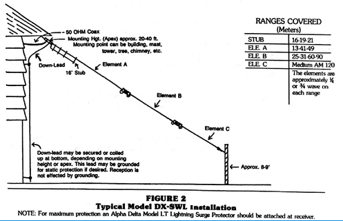
“[The Alpha-Delta DX-SWL Sloper] is very well built. Actually, over-built for listening. Easy to erect with the feed point being up high. And really works well on the SW bands (including Tropical) and MW too. Fully preassembled. Down-side is it is kinda obtrusive with the heavy wire and large coils.”
Click here to check it out at Universal Radio.
Par EF-SWL $72.95
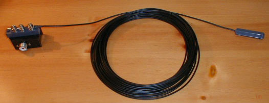
“[The EF-SWL is very popular] these days. It does work best with a ground, but still usable without. It is interesting, as it can be configured many different ways. I suspect it is popular because it is very easy to erect, and very, very stealthy. (Increasingly important these days). And the wire is flexible, not too thick and not obtrusive. Seems more immune to noise than others. Priced right.”
Click here to check it out at Universal Radio.
Thank you, Fred!
I have some experience with the Par EF-SWL antenna. It offers excellent performance and the antenna line has a durable black coating that makes it nearly impossible to spot from a distance. I’ve even taken the EF-SWL on travels and posted a review a few years ago. I agree that it performs very well.
I have a friend that’s relied on the Alpha-Delta DX-SWL Sloper as his main SWL antenna for years. He lives in an urban area and I’ve been favorably impressed with its performance. I agree with Fred–it’s incredibly durable and beefy! Built like a tank.
Of course, there are also incredibly low-profile antennas like the Bonito Mini Whip (check out some of Oxford Shortwave’s posts) but note that some versions don’t handle a noise-rich environment very well.
Post readers: Please comment if you know of other off-the-shelf antenna options–especially those you have personal experience using and installing.