 Many thanks to SWLing Post contributor, Dan Robinson, for the following guest post and review:
Sangean v Tecsun in the Battle of Late Shortwave Era Portables: The ATS909x2
by Dan Robinson
Some years ago – actually more than a decade – I decided to give Sangean a shot at winning me over in the shortwave portable category.
I had and still do use numerous portables with a bias toward the classic SONY, Panasonic, and Grundig sets. The ones that made an impression stayed, often in multiples, as anyone can see if they visit the radio shack here in Maryland.
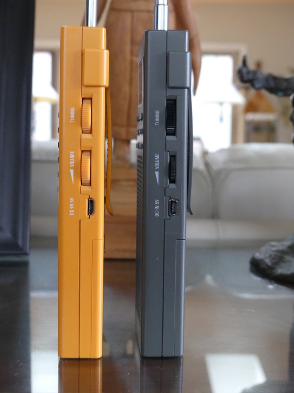
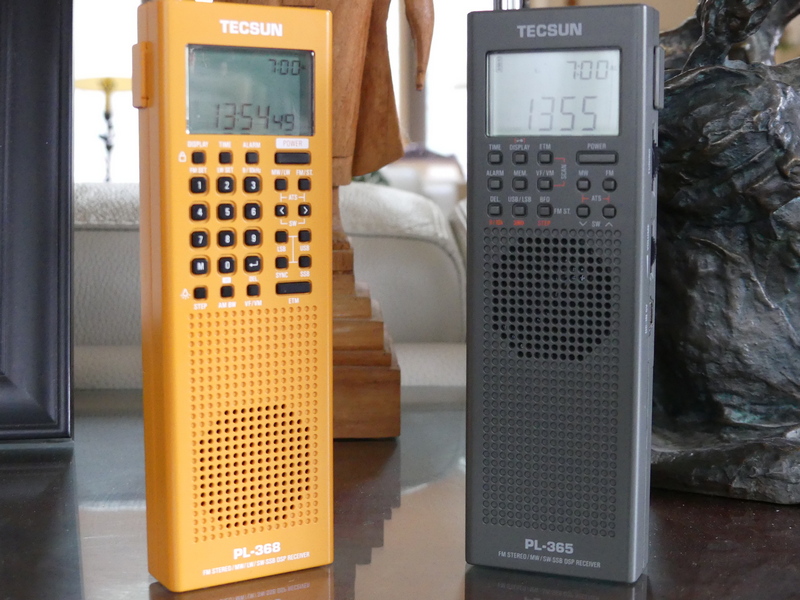
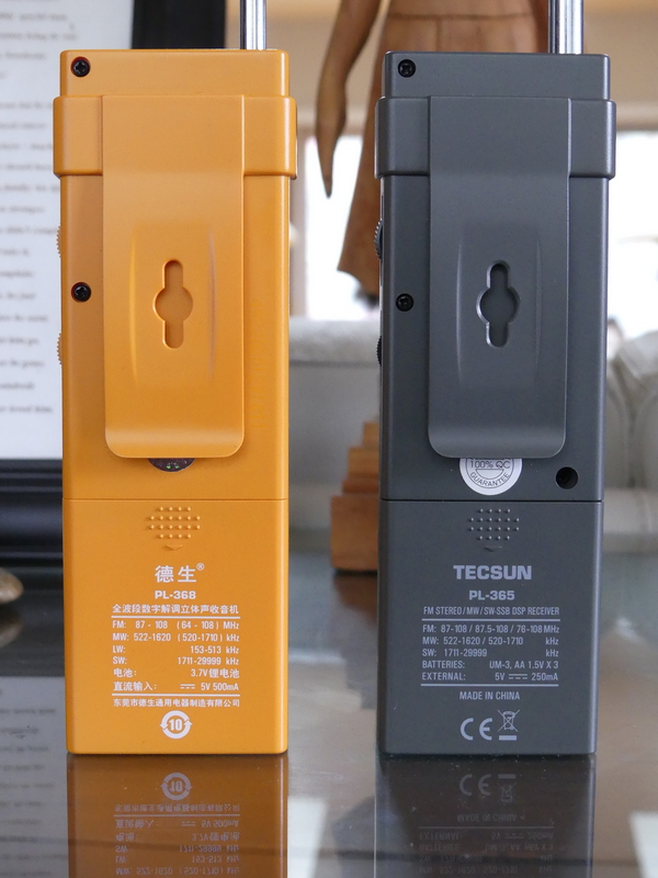
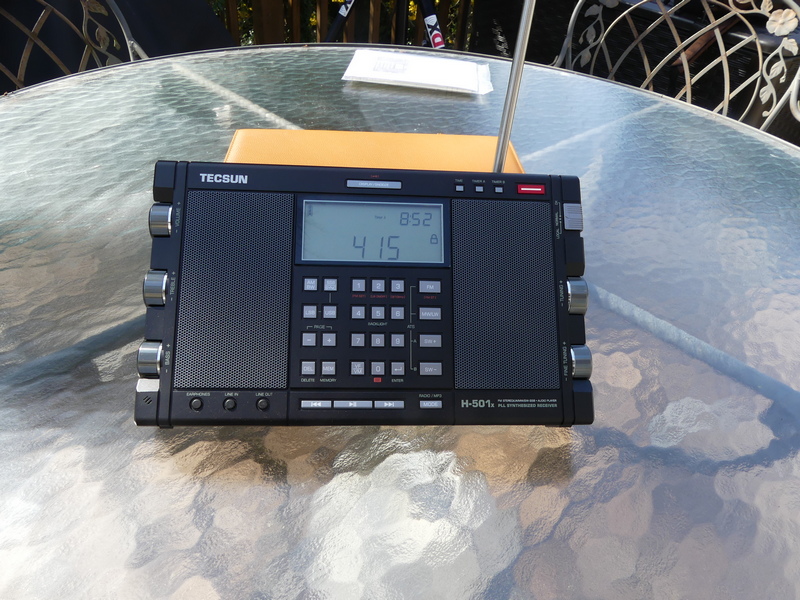
These include, for those interested: the Panasonic RF-B65, SONY ICF-SW77, ICF-2010, ICF-PRO80, ICF-7600D, ICF-7700, ICF-SW1000T, ICF-SW55, ICF-SW100s, ICF-SW07, Grundig Satellit 500, to which were added in more recent times the Toshiba RP-F11, XHDATA D-808, and Tecsun portables ranging from the PL-365 and new PL-368 to the PL-880, PL-990x, H-501x, and S-8800.
Sangean has generally not been on that list. There’s a good reason – I just never considered Sangean to be competitive when it comes to portables, though they did have some excellent larger sets such as the ATS-803A that made the first forays into multiple bandwidth options.
My last experience with Sangean was with the ATS-909. I liked the looks and capabilities of that receiver, and even went to the point of having mine modified by Radio Labs. But those mods were underwhelming, in my view, and the original 909 always seemed to me to be deaf when using the whip antenna.
That issue continued unfortunately with the 909x. Some of you may have seen a video I did a few years ago in which I set a 909x against a SONY SW-07 and Panasonic RF-B65. This was done barefoot with only the whip antennas, but near a window. In short, the other two radios wiped the floor with the 909x.
It took a surprisingly long time for Sangean to update the 909x with the 909×2, during which companies asked valid questions about the need for further development of world band portables.
Eton turned the market on its head when it introduced the still superb E1/XM which competed with the very end of SONY portable production, and co-designed with R.L. Drake added such superb features as Passband Tuning and three selectivity positions.
Meanwhile, Tecsun plugged away, introducing an impressive array of portables including the PL-600 series, then the 880 and now the 990x and H-501 portables.
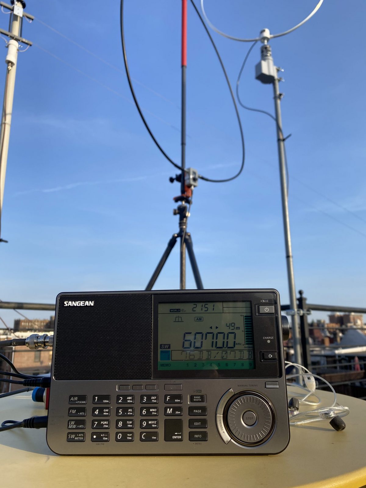
So, now the 909×2 is here and with its 073 firmware upgrade has become a bit of a holy grail for portable receiver users. There have been a number of excellent reviews, including Dave Zantow’s deep dive, and some others here on SWLing Post.
I’m going to give you my impressions, using the really detailed Zantow review as a base. I received my 909×2 from Amazon just today – it is a 073 firmware which confirms that new supplies have the upgrade.
SENSITIVITY ON WHIP
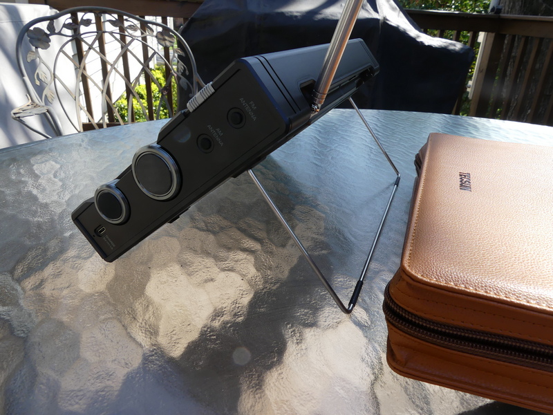
First, let’s get the elephant in the room out of the way. Although I have not undertaken detailed technical testing of the 909×2 – nor do I have the equipment to carry this out – it does seem that Sangean may have finally tackled this crippling flaw that rendered the old 909x nearly useless when using it only on the whip. I’ll undertake further testing and comparisons with some of my other portables to confirm this. The whip antenna itself is robust – solid and long, something that Tecsun could take note of.
AIR BAND
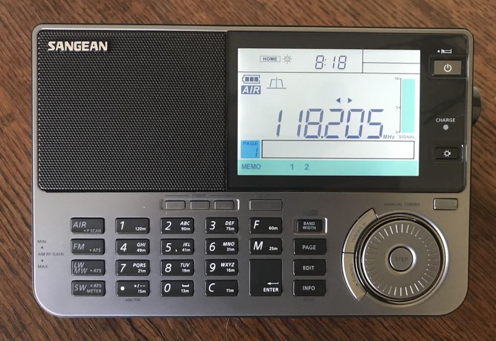 Inclusion of air band on this radio is a major selling point for those interested in this type of monitoring. My initial tests showed the 909×2 to be quite sensitive and useful – I managed to pick up no fewer than five airport comms frequencies in my area here in Maryland.
SELECTIVITY / AUTO-BANDWIDTH
The 909×2 really shines with FIVE available selectivity options that are easily selectable in shortwave mode. It would have been nice to be able to actually see the values of each filter as one scrolls through, but that’s a minor point. Think about it – in shortwave AM mode, this is the number of selectivity positions that one finds on such power house communication receivers as a Drake R8. Amazing that we now have that in a portable. On the negative side, I find the auto-bandwidth feature on the 909×2 to be nearly useless, as useless as the similar feature found on Tecsun receivers. The automatic switching is distracting and annoying. My advice to users: forget this, and stick with manual bandwidth control. My advice to Sangean – I wish they had left this feature out but given us multiple bandwidths in SSB.
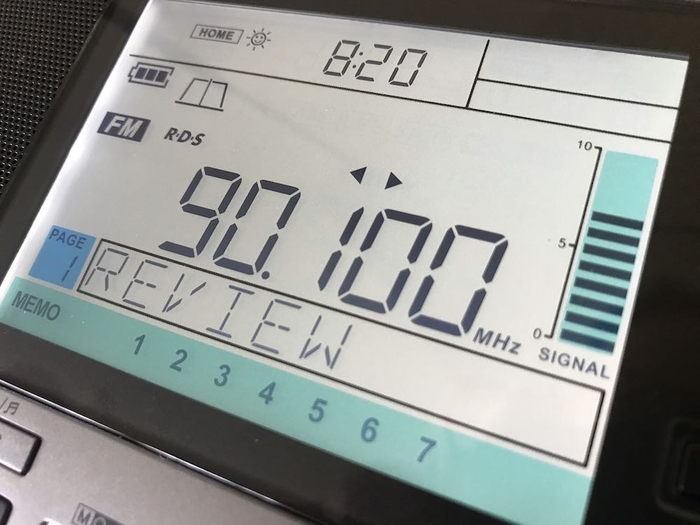
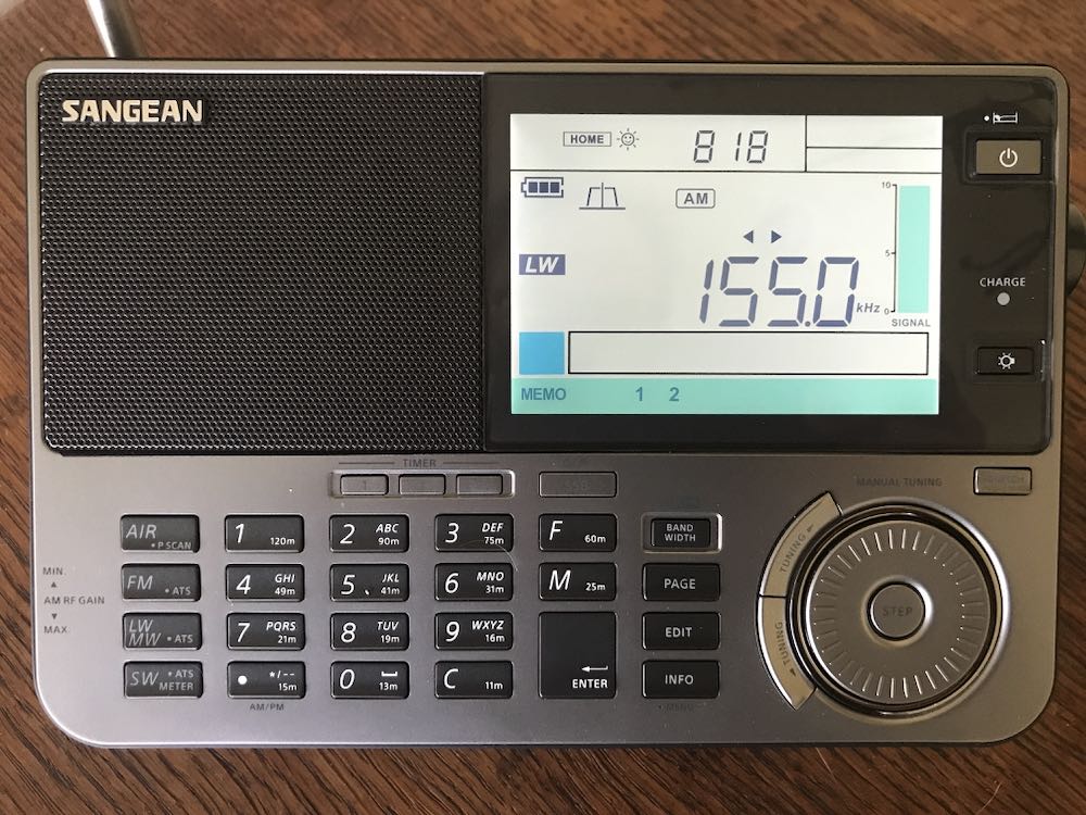
LCD AND BRIGHTNESS
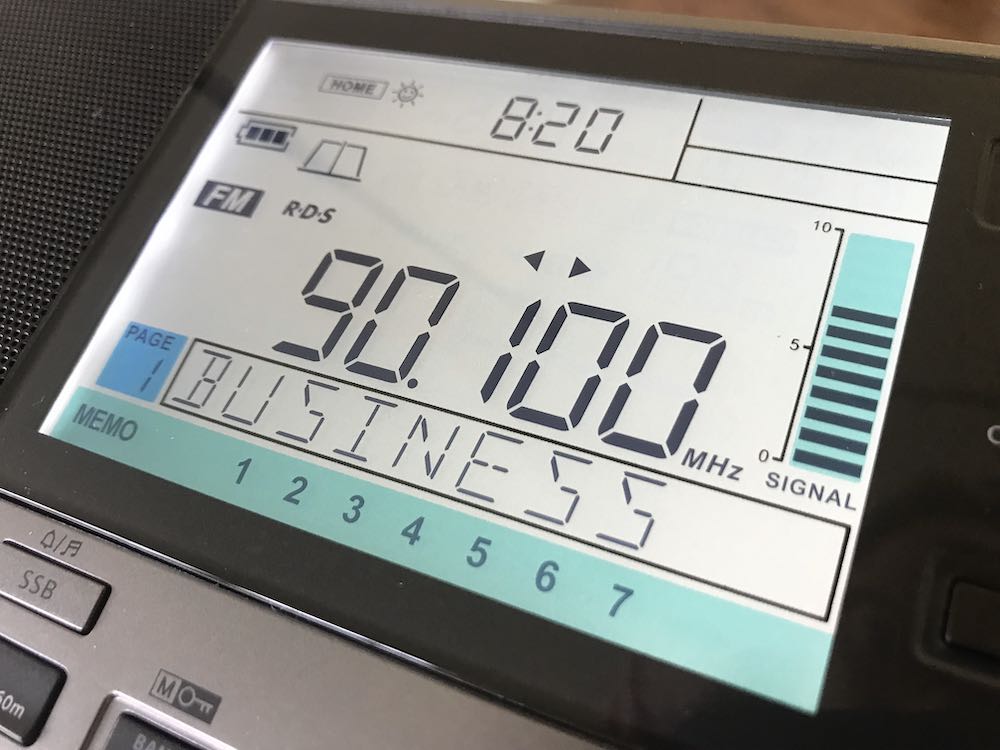 Sangean hits it out of the park with this multi-stage lighting for the display. Simply superb and the kind of quality we could only hope for from other manufacturers.
MAIN TUNING / DETENT CONTROL
I found the detents on the old 909x to be annoying – indeed, modifications have been available that could remove this feature. But Sangean being Sangean, the detent wheel remains in the 909×2 and it is not a deal killer.
AUDIO QUALITY
The radio retains the excellent audio of the 909x – I am not sure the 909×2 exceeds what one hears from a Tecsun 990x or H-501x but it’s right up there and competitive.
POWER SUPPLY
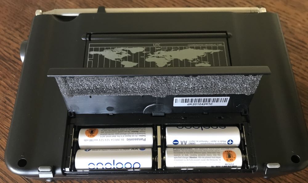 As others have noted, thanks to Sangean for sticking with AA cells. Together with internal charging when using Ni-Mh cells this is a major selling point. On the other hand – competitor Tecsun went a step farther with its H-501x which though it uses 18650 lithium batteries, has dual batteries, one of which can be held in standby, and switchable charging. That’s a design feature that you really have to respect.
VARIABLE RF GAIN
Again, as noted by others Sangean retained the extremely useful thumb wheel RF gain control. This is an excellent feature.
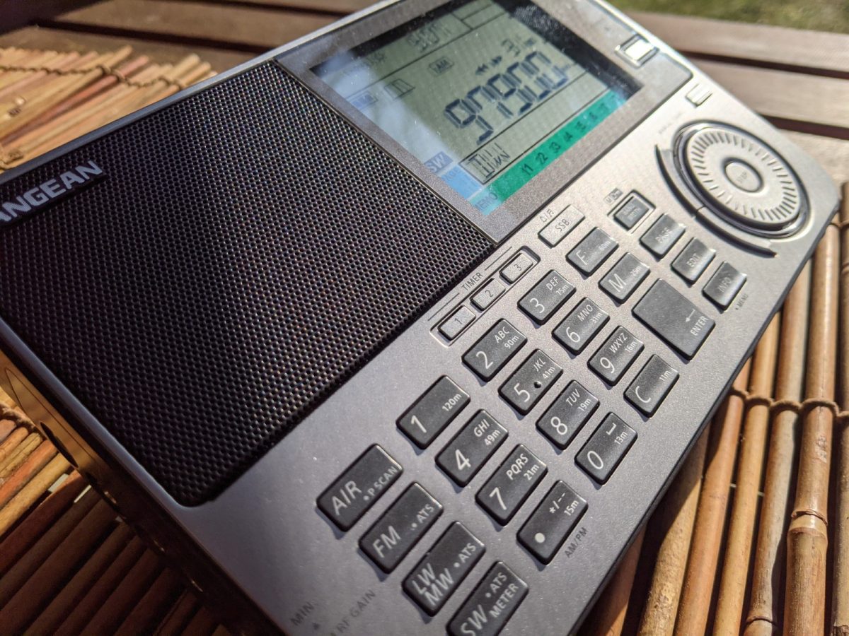
KEYPAD
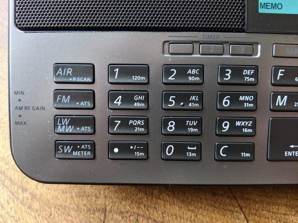 Another home run for Sangean when it comes to the keypads on the 909×2, which can be compared in this respect to the Tecsun H-501x which itself improves upon the 990x when it comes to front panel control. Time will tell, however, and we shall see if the keys on these radios hold up in heavy use.
UP/DOWN SLEWING
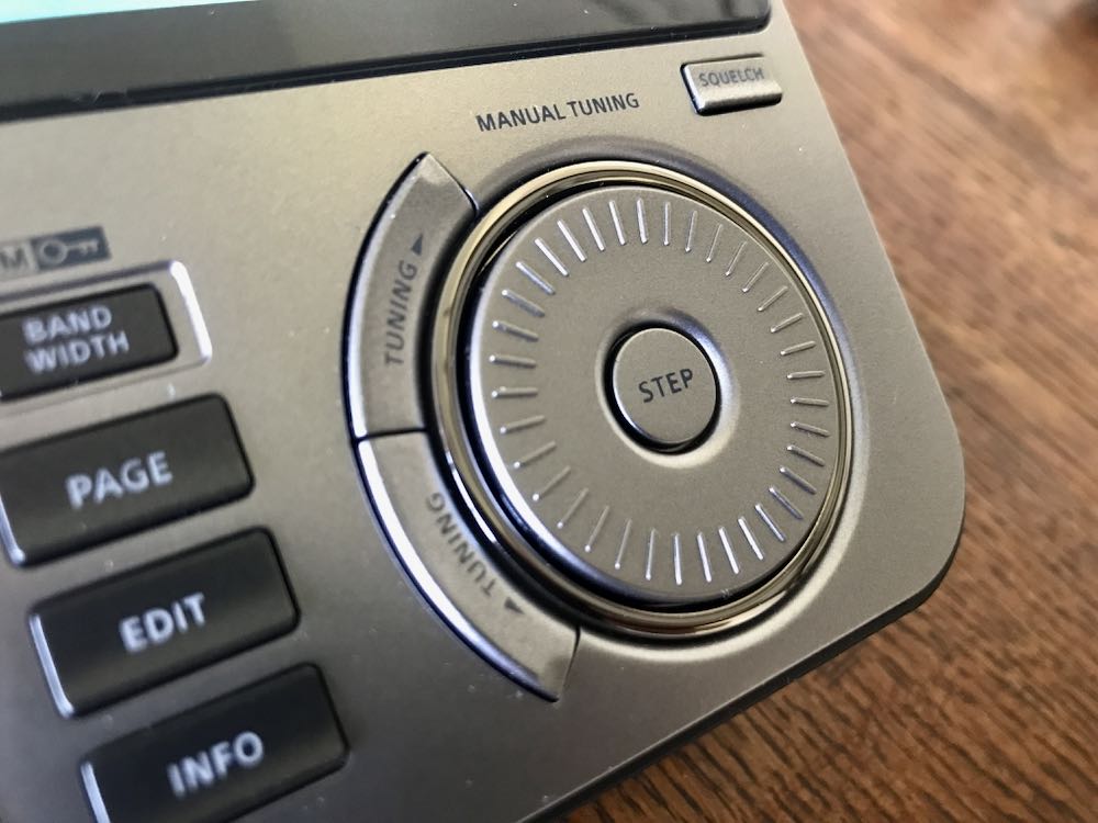 These controls which sit outside the circular main tuning knob are excellent, and reminds one of the slewing buttons on the SONY 7600GR, SW1000T and SW100.
S-METER / DISPLAY
RSSI and SN Digital Signal Strength Information are provided on the beautiful 909×2 display. This is an improvement over the Tecsun signal strength/SNR meters that I wish would be redesigned, if in fact Tecsun has any intention of future modifications to their portables.
NO SOFT MUTING
Thank goodness we don’t have to deal with the annoying soft muting issue that is still seen in some other portables (the XHDATA D808 comes to mind along with the Eton Executive). Soft muting quite simply ruins a listening session and it’s baffling that any manufacturer still puts it in.
NEGATIVES (I AM IN TEARS)
OK, close all airtight doors and prepare to dive! Here are the negatives I see with the 909×2. I held off obtaining one of these radios because I knew there would be issues. And I was disappointed enough in the past with the 909x and 909 before it that I had almost decided not to go for it.
SIGNS OF LONGWAVE RECEPTION PLAGUED BY CROSS-MOD FROM MEDIUMWAVE
 On my particular unit – it remains to be seen whether this is true for others – long wave seems to be near useless. The band is filled with mediumwave stations bleeding through. Turning down the RF obviously helps but I still hear AM stations here in the DC area, when I am in LW mode.
SSB PERFORMANCE
ALERT FOR SANGEAN AND ALMOST A DEAL BREAKER – as mentioned in the Zantow review, and in other comments I have seen on the 909×2, the drop in level from AM to LSB is a killer negative.
This is less noticeable in MW. But if you are in shortwave and have turned your volume up on any particular station, say a strong one such as Greece on 9,420 kHz or Spain, or an AM station, and you then switch to LSB it is like you have almost lost the signal. This simply needs to be fixed. Level on USB seems fine and acceptable, but LSB on shortwave requires immediate upwards adjustment of volume, only to have to reverse the process when returning to AM mode. I find this problem to be sufficiently serious that I would recommend against obtaining a 909×2 until Sangean finds a way to fix it. This issue is on the same level of BAD as the still unsatisfactory SYNC mode in all three of Tecsun’s shortwave portables. In fact, I may return the 909×2 I obtained and wait until a fix for this emerges.
Example Video
In this video, I demonstrate the extent of the problem as seen on this particular unit of the 909×2, which carries a serial number dk201043181.
Dave Zantow says his unit does not have this issue, so there is a possibility this is due to unit to unit variation. As you can see, with a strong signal such as 12,160 kHz — switching from AM to LSB instantly reduces listenable level, and signal as measured on the 909×2 drops to zero bars or near zero. In USB, the reduction is less severe. Regardless, having to perform adjustments with main volume just to struggle to hear any signal in SSB is a bit ridiculous. This kind of thing is not seen on the Tecsun H-501x or 990x though as Dave correctly points out, Tecsun receivers are not exactly great performers in SSB. On Tecsun receivers, there is a slight processor pause while the receiver makes the switch into LSB or USB, without the sharp reduction in listenable level.
CALIBRATION ISSUES WITH NO WAY TO ADJUST
Imagine my joy when I first began using the x2. Initially, it seemed to be smack on frequency – I tried this on WMAL, the powerhouse local AM station here in the DC area, and then again with stronger stations on shortwave, such as 12,160 kHz. Ah, I said to myself, Sangean has some decent QC and paid attention. About 30 minutes later, however, what I found matches the Zantow review. Stations are consistently low of the tuned/displayed frequency by as much as 300 Hz. The reason this is so disappointing is that I feel Sangean could have taken a clue from Tecsun and provided a re-calibration function (unless it exists and we aren’t being told about it). On Tecsun radios, the re-calibration capability is the major counter-punch to poor synchronous mode – in my view, one can live with flawed SYNC on a 990x or H-501 or PL-330 as long as you can adjust and at least have zero beat or close to it across frequencies. At the same time, as Zantow points out, no one should be expecting TCXO level performance from portables such as these. However, it is a bit disappointing that after all these years and redesign of the 909x to add some really nice features, they’re still landing up to 300 Hz from a tuned frequency. On the other hand, is this really any worse than one would see from an off-tuned SONY ICF-2010? No, and adjusting those older receivers required surgery.
CONCLUSIONS
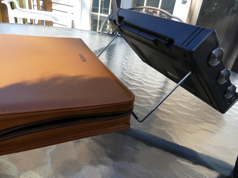
 I really like the 909×2. There simply is something about this design that Sangean knew was a winner when it first arrived on the market years ago, so it’s not surprising that Sangean stuck with it. It’s clear that some hard thinking went into the step up from the old 909x, notably the larger LCD, addition of finer step tuning to make SSB easier, the robust antenna and the still pretty darn good audio through the wonderful speaker. The 909×2 is a radio that you can imagine guests would comment on if it were sitting on your coffee table – it just looks THAT GOOD.
But then here in 2021, so does a Tecsun H-501x LOOK THAT GOOD. As I noted above, where the Tecsuns fall down – with their still challenged synchronous mode – they make up for with the ability to re-calibrate.
That is a huge feature and one that Sangean struck out on, though surely Sangean designers had to know the 909×2 would appeal both to listeners and to hobbyists with obsessions about frequency accuracy.
To repeat, I really (really) like the 909×2. But another area where the receiver strikes out is the problem with sharp reduction in LSB mode. Seriously – you have to crank the volume control up to at least 50 percent to hear ANYTHING when you’re in LSB, whereas USB requires going only up to about 30 percent. Then when you’re completing your carousel back to AM, you have to be sure not to still have the audio up at 50 percent or more to avoid blowing your speaker.
Again, as I said above, the calibration/drift issue on the 909×2 can be lived with. The problem with LSB, in my opinion, cannot or should not be tolerated. So, the question is, do you want to purchase a 909×2 now that still has that LSB audio issue, or wait a while until Sangean gets its act together?
These and other earthshaking questions are before us here in 2021. We have some of the best portables ever made by anyone in a time of sharply declining shortwave use, but they each have their flaws.
I don’t usually do a star rating or RECOMMEND / NOT RECOMMEND for radios. This time, I am going to make an exception and it links directly to the issue of the LSB problem on the 909×2. These radios simply should not have been allowed to enter the market with this being as serious a problem as I think it is. For that reason, I honestly cannot recommend a Sangean 909×2 until this is corrected.