Tag Archives: Ham Radio

The EMTX: How to build an 8 component 40/30 meter QRP emergency transmitter

Many thanks to SWLing Post contributor, Kostas (SV3ORA), for sharing the following guest post which originally appeared on his radio website:


Emergency transmitter: An 8-component, high-power 40m/30m transmitter to get you quickly on the air

by Kostas (SV3ORA)

Introduction

QRP is all about doing more with less. This is more than true, with the construction of this cheap, simplistic transmitter presented here. It is designed primarily as an emergency transmitter (EMTX) that can be built or serviced in the field or at any home. However, it can be used as a HAM radio transmitter as well. Do not judge by its low components count though. This transmitter is powerful, more powerful than anything the QRPers would dream of. It is just remarkable how 8 components can lead in so much output power, that lets you communicate with a big part of the world, when propagation conditions are right. It is very difficult for a circuit to match that kind of simplicity in balance with such performance.

Following my detailed instructions, the EMTX can be reproduced easily, within hours. The result is always success, this is one of the circuits that are not critical at all and a successfully working transmitter can be reproduced every time. I have built this transmitter several times, using similar components (even toroids) and it always worked. The transmitter meets the next expectations:

1. Output power (including harmonics): A few mW up to 15W (depended on transistor, crystals and voltage/current used) at 50 ohm.
2. It can drive any antenna directly, 50 ohm or higher impedance, without external tuners.
3. Bands of operation: Currently 40m, 30m
4. Mode: CW, Feld-Hell (with external switching circuit), TAP code and any other ON/OFF keying mode. AM modulation has been easily applied too.
5. Options like reverse polarity protection diode (useful in the field when testing different unknown polarities PSUs) and current meter (for easier tuning) are available.

The challenge

The purpose of this transmitter is to be used primarily as an emergency transmitter. This poses several challenges that influence the design of the transmitter:

1. It must be able to be built or serviced easily in the field or at any home, with components that could be salvaged from near by electronics sources or a small electronics junk box. This means that components count should be kept very low and they must not be rare to find but commonly available parts. As a side effect cost would also be kept small, if one is to buy any component. Also, the active components must be interchangable with many other devices without the need for the design or the rest of the circuit components to be changed.

2. It must be able to operate from a very wide range of DC voltage sources and at relatively low current, so that common house power supplies could be used to supply power to it. Such devices include linear or switched mode power supplies from laptop computers, routers, printers, cell phone chargers, Christmas lights or any other device one might have available.

3. It must be capable of transmitting a powerful signal, so that communication is ensured. An emergency transmitter that is capable of a few mW of output power, might be heard locally (still useful, but there are handheld devices for that already) but isn’t going to be of much usage if it can’t be heard really far away.

4. It must be capable of loading any antenna without external equipment required. In an emergency situation, you just don’t have the luxury of building nice antennas or carrying coaxial cables and tuners. There may be even extreme cases where you can’t even carry a wire antenna and you depend on salvaging wire from sources in the field to put out a quick and dirty random wire antenna.

5. Adjustments of the transmitter should be kept minimum without the help of any external equipment and there must be indication of the correct operation of the transmitter or the antenna in the field.

Components selection

The transistor:
This transmitter has been designed so that it can operate with any NPN BJT in place. This includes small signal RF and audio transistors and high power RF transistors like the ones used on HF amplifiers and CB radios. Despite 2sc2078 is shown in the schematic, just try any NPN BJT in place and adjust the variable capacitor accordingly. When you are in the field, you do not have the luxury of finding special types of transistors. The transmitter must operate with any transistor in hand, or salvaged from near-by equipment. Of course the power capability of the transistor (as well as the crystal current handling) will determine the maximum VCC and current that can be applied to it and hence the maximum output power of the transmitter. Some of the most powerful transistors I have used, come out of old CB radios, such as the 2sc2078, 2sc2166, 2sc1971, 2sc3133, 2sc1969 and 2sc2312. There are many others. As an example, the 2sc2078 with a 20v laptop PSU, gave 10-12W of maximum output power into a 50 ohms load.

Schematic of the 8 components EMTX for the 40m/30m bands. Components with gray color are optional.

The crystal:
This is the most uncommon part of the transmitter. You have to find the crystal for the frequency that you want to operate on. Crystals within the 40m or 30m CW segments are not that common. Further more if you operate the transmitter at high powers and currents, you will notice crystal heating and chirp on the frequency of the transmitter. The current handling capability of your crystal die inside the crystal case, will determine the chirp and the amount of crystal heating. You can still work stations with a chirpy transmitter provided that the chirp is not that high, so that it can pass through the CW filters of the receivers. However, if a small chirp annoys you or if this chirp is too much, then you have to use these vintage bigger size crystals (e.g. FT-243), that can handle more current through them. But these are even more uncommon today.

The approach I have used in my prototype, was to connect more than one HC-49U crystals of the same frequency in parallel, so that the current is shared among them. This reduced the chirp at almost unnoticeable levels, even at high output power, just if I was using a single FT-243 crystal, or even better in some cases. Again, this is optional, but if you want to minimize chirp (and crystal heating) without searching for rare vintage crystals, this is the way to go.

A bit of warning. If you notice a very high chirp when plugging in a crystal to the EMTX, you should consider this crystal as inappropriate for this transmitter, as it cannot handle the current required. If you continue to use this inappropriate crystal, you could easily crack it inside and set it useless. Don’t use these tiny HC-49S crystals, they won’t work.

The current meter:
A 1Amp (or even larger) current meter can be used to monitor the current drawn by the transmitter during key down. The recommended current operating point is anywhere between 450mA to 1A, depended on the output power (and harmonics) level you want to achieve. The current point is set by the variable capacitor. I would avoid setting the current to more than 1Amp, although it can be done. The use of the current meter is optional, but along with the incandescent bulb, will give you a nice indication of the correct tuning of the transmitter, so that you do not need to have an external RF power meter connected to the transmitter output. If you do have, then you can remove the current meter. If you don’t have a 1Amp analogue meter available, but a smaller one, you can parallel a low value power resistor across the meter. In my case, I only had a 100uA meter and I paralleled a 0.15 ohms 5W resistor across it to scale down 1Amp to 100uA, The resistor value depends on the internal meter resistance so you have to calculate this for your specific meter. When the 2sc2078 is used at 20V, 500mA in the current meter indicates around 5W of output power, 600mA indicates around 6W, 700mA 7W, 800mA 8W, 900mA 9W and 1A around 10W. So the current meter can be used as sort of power meter without the need to do any scaling on it.

The incandescent bulb:
A current meter alone, without the use of the incandescent bulb, will not give you the right indication of the operation of the transmitter. In some cases, the transmitter might be drawing current without actually generating much, or even any RF. When you are in the field you do not want to carry extra monitoring equipment with you. The incandescent bulb will light on when the transmitter oscillates. It monitors the actual RF signal, so it’s brightness changes according to the amount of RF power the transmitter produces. Along with the current meter reading, this is just what you need to know in order to set the variable capacitor properly. Note that the bulb will not lit at very low signal levels. The one used in the prototype starts to glow up from a bit less than 1W. Miniature incandescent bulbs may not be that easy to find nowadays. However, there is a good source of these, that almost anyone has in their houses. This source is the old Christmas lights. You do save old Christmas lights, don’t you? The incandescent bulb indicator as well as it’s single turn winding on the transformer, are optional components. If you have an RF power meter connected to the transmitter, you can remove these.

The diode:
The protection diode is an optional component to the circuit. If you are in the field, correct polarity of a power supply may not be obvious. Without a multimeter it might me difficult to determine the correct polarity of the PSU. A power diode (I used a 6A one) will protect the transistor from blowing up in the event that reverse polarity is connected to the circuit.

The Cx and Cy:
The Cx and especially the Cy capacitors need to be of good quality. The Cy will get hot on high output power if it isn’t. In the tests, I have used homemade gimmick capacitor and even double-sided PCB as a capacitor for Cy and they all got hot at high power. Silver mica capacitors run much cooler and they do make a small difference in the output power, so I suggest to this type. Cy must be able to handle quite a lot of voltage, so silver mica type is ideal.

The variable capacitor:
The variable capacitor can be air variable or ceramic, although I prefer air variables in tis application. In any case it must be able to handle a high voltage just as the Cy.

The key:
The key directly shorts the transistor emitter to the ground, therefore it is a part of the active circuit. For this reason, I suggest the key leads to be kept as short as possible. The key must be able to handle the voltage (20v) and current (up to 1A) on its contacts, which is usually not a big deal.

Transformer construction

The construction of the transformer is shown below step by step. Note that if you decide that you don’t need to drive higher impedance loads but just 50 ohm ones (eg. antenna tuners or 50 ohm matched antennas), you just need to wind 2t in the secondary and not 14t. You also don’t need any taps of course.

Step 1:

Take a piece of 32mm external diameter PVC pipe from a plumber’s shop. Alternatively, a suitable diameter pills box can be used, or any other suitable diameter plastic tube.

Step 2:

Cut a 4cm piece out of this tube. 4cm is the minimum length required.

Below a 4cm PVC tube has been cut in size.

Step 3:

Wind 16 turns of 1mm diameter enameled wire onto the PVC pipe and secure the winding in place as shown in the picture below. Notice the winding direction of the wire. This is the primary of the transformer, the one that is connected to the two capacitors. Notice that this winding is wound a bit offset to the right of the pipe.

Step 4:

Wrap the winding with 3 turns of PTFE tape. It can be bought at any plumber’s shop, just like the PVC pipe. The PTFE tape will help in keeping the second layer turns in place and it will provide extra insulation.

Step 5:

Wind 2 turns of 1mm diameter enameled wire on top of the primary winding and secure the winding in place as shown in the picture below. Notice the winding direction of the wire, as well as it’s position relative to the primary winding. This is the feedback of the transformer, the one that is connected to the collector of the transistor.

Step 6:

Wind 14 turns of 1mm diameter enameled wire on top of the primary winding, starting from just next to the 2 turns one and secure this winding in place as shown in the picture below. Notice the winding direction of the wire, as well as its position relative to the primary and the 2 turns windings. This is the secondary (output) of the transformer, the one that is connected to the antenna. At this point do not worry about the taps yet.

Notice in the picture below, the way the windings are secured in place onto the pipe. The wire ends are passed through the pipe using small holes and then bent towards the ends of the pipe and once more to the surface of the pipe, where the connections will be made.

Step 7:

Wind 1 turn of 1mm diameter enameled wire onto the pipe and secure the winding in place as shown in the picture below. Notice the winding position relative to the other windings. This 1 turn winding is placed about 1cm away from the other windings. This is the RF pick up winding, the one that is connected to the incandescent bulb.

Step 8:

Use a sharp cutter (knife) and carefully scrap the enamel of all the windings ends. Do not worry if you cannot scrap the enamel at the bottom side of the wire ends (that touches to the pipe). We just want enough copper exposed to make the connection.

Step 9:

Tin the scrapped wire ends, taking care not to overheat them much.

Step 10:

Now it’s time to make the taps on the secondary winding. Use a sharp cutter (knife) and very carefully scrap the enamel of the wire at the tap points (number of turns). Take much care not to scrap the enamel of the previous and the next turn from each tap point. Do not worry if you just scrap the enamel at the top of the wire (external area). We just want enough copper exposed to make the connection.

Make each tap, a bit offset from the near by taps, like shown in the pictures. This will avoid any short circuits (especially at the 4, 5 and 6 taps) and it will allow for easier connections, especially if alligator clips are used to connect to the taps.

Step 11:

Tin all the tap points, taking care not to overheat them.

Step 12:

This step is optional and it depends on how you decide to do the connections to the taps. You may solder wires directly to the tap points, but in my case I wanted to use alligator clips, so I did the next: I took a piece of a component lead and soldered it’s one end to each tap point. Then I bent the component lead to U-shape and cut it accordingly. This created nice and rigid tap points for the alligator clip.

Step 13:

This step is optional and it depends on how you decide to mount the transformer to your enclosure. In my case, I wanted to create three small legs for the mounting. I cut three pieces of aluminum straps and made holes at both their ends. I made three small holes onto the transformer pipe end and mounted the aluminum straps using screws. After mounting them, I shaped the straps to L-shape. Then I used three more screws to mount the transformer to the enclosure.

The completed transformer is shown in the pictures above and below. The 6 connection points at the bottom of the pipe, are the low voltage points, whereas the 2 points at the top of the pipe, are the high voltage points.

If you have built the transformer as described, the bottom connections are as follows (from left to right):

Wire end 1, connected to the incandescent bulb
Wire end 2, connected to the incandescent bulb
Wire end 3, connected to the current meter
Wire end 4, connected to the current meter
Wire end 5, connected to the GND (ground)
Wire end 6, connected to the transistor collector

The top connections are as follows (from left to right):

Wire end 1, connected to the 25pF variable capacitor and the Cy fixed.
Wire end 2, is the 14th secondary tap and it is left unconnected, or tapped to the appropriate impedance antenna.

Videos of the EMTX in operation

I have made two small videos of the EMTX in operation.

The first 13.5MB video (right click to download), shows the operation when the transmitter is set for a bit less than 10W of output power.

The second 3.5MB video (right click to download), shows the operation when the transmitter is set for about 5W of output power.

EMTX chirp analysis

Every self-exited power oscillator (and even many multi-stage designs) exhibits some amount of chirp. Chirp is mainly considered as the sudden change in frequency when the power oscillator is keyed down. Apart from chirp, there is also the longer term frequency stability that may be considered. The chirp in the EMTX is surprisingly low, if it is built properly. Hans Summers, G0UPL has performed a chirp analysis on my EMTX (PDF) and the EMTX built by VK3YE and presented on YouTube. Hans, performed the analysis from the video/audio recordings of both transmitters. I sent him two videos, one with the EMTX set for an output power of 10W and one where it is set for 5W. The chirp at worst case (10W) was about 30Hz and at 5W in the order of 10Hz or so. Being so small, the chirp is almost undetectable by the ear and it surely poses no problems when passing the tone through narrow CW filters. This is an amazing accomplishment from a transmitter so simple and so powerful.

EMTX harmonics measurement

Every unfiltered transmitter will excibit harmonics at it’s output. This means that the output waveform has some distortion in comparison to a pure sinewave. Many of the transmitters I have seen, present a very distorted output waveform and absolutely need a LPF if they are to be connected to an antenna. I can’t say that this is true for the EMTX, because surprizingly, it has low distordion, despite the high output power it can achieve. Although a LPF is always a good idea, it is not that much needed on the EMTX. However you have to use one to comply with the regulations.

The image above, shows the measurements on the output of the EMTX, when it is set closely to 10W at 50 ohms. The main carrier is exactly at 9.9W and all the harmonics are less than 50mW! Also, the harmonics, do not extend into the VHF region.

The image below, shows the measurements on the output of the EMTX, when it is set closely to 5W at 50 ohms. The main carrier is exactly at 5.17W and all the harmonics are less than 9.6mW! Again, the harmonics, do not extend into the VHF region.

These small harmonics levels aren’t going to be heard very far at all, compared to the powerful carrier. This means only one thing. A LPF, although a good practice, is not mandatory in this transmitter. But you should better use one so that you comply with the regulations.

Many HAMs use just a watt meter to measure the output of their homebrew transmitters. This is not the proper way of doing it, because the watt meter is a non-selective meter. It will measure both the fundamental carrier and the harmonics, without being able to distinguish them. So in an unfiltered transmitter, or in a transmitter with a simple (often non measured) LPF, this way will give a totally false reading of the output power of the transmitter at the set frequency.

The proper way of accurately measuring the output power of a transmitter and the harmonics levels, is a spectrum analyzer. The FFT available in many modern oscilloscopes, having a dynamic range of approximately 50-55dB, is adequate for this purpose as well. A 50 ohms dummy load must be connected at the transmitter output and then the high impedance probe of the scope, is connected to the output of the transmitter as well. This was the way that the above measurements have been performed.

WebSDR tests

Here are some test transmissions, to determine how far one can get with such a transmitter. I have to say that there is an antenna tuner between the EMTX and my inefficient short dipole (not cut for 40m and not even matched to the coaxial). However I could still cover a distance of more than 2500Km even on the 5W setting.

A screenshot of the transmitter signal, as received on a WebSDR 2500Km away and when the EMTX is set for an output power of 10W.

Below, is a picture and an audio recording of the transmitter signal, as received on the same WebSDR and when the EMTX is set for an output power of 5W.

Photos

Pictures of the finished transmitter. You don’t have to build it that nice-looking if you don’t care.
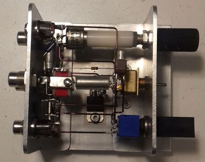
EMTX prototype built on a breadboard. Yes it worked just fine onto a piece of wood.


This is a phenomenal project, Kostas. Thank you so much for sharing it with us. I love the simplicity of this design–truly form following function. With a little patience, anyone could build this transmitter.

Check out this project and numerous others on Kostas’ excellent website.

Spread the radio love

Radio Waves: FCC Warn Extremists Using Radio, ARRL Statement, Historic Radio Tirana Building, and Bob’s Replica Broadcast Studios

Radio Waves:  Stories Making Waves in the World of Radio

Because I keep my ear to the waves, as well as receive many tips from others who do the same, I find myself privy to radio-related stories that might interest SWLing Post readers.  To that end: Welcome to the SWLing Post’s Radio Waves, a collection of links to interesting stories making waves in the world of radio. Enjoy!

Many thanks to SWLing Post contributors Pete, Bill, Trevor R. and Steve Reardon for the following tips:


Blocked from social media, extremists discuss turning to radios to plan attacks, FCC warns (CNN Business)

The US government is warning that groups could rely on radio equipment as an alternative to social media to plan future criminal activities.

In a stark warning Sunday, the Federal Communications Commission’s enforcement bureau said people coordinating or conducting criminal activity over radio waves are breaking the law.

“The Bureau has become aware of discussions on social media platforms suggesting that certain radio services regulated by the Commission may be an alternative to social media platforms for groups to communicate and coordinate future activities,” the FCC said in its warning Sunday. “Individuals using radios in the Amateur or Personal Radio Services in this manner may be subject to severe penalties, including significant fines, seizure of the offending equipment, and, in some cases, criminal prosecution.”

The FCC licenses certain signals for people to broadcast over radio waves. Those messages are generally protected by the US Constitution’s First Amendment. But the FCC reminded radio licensees and operators that it is prohibited to transmit “communications intended to facilitate a criminal act.” People are also not allowed to encode their messages to obscure their meaning from law enforcement.

The laws governing airwaves apply to amateurs broadcasting with personal ham radios, which can reach long distances. But they also apply to people using Citizens Band (CB) radios commonly used for communication between truckers — or even walkie-talkies.

In the wake of the January 6 Capitol riots, Facebook (FB), Twitter (TWTR) and other mainstream social networks have become more vigilant about policing people who use their platforms to plan or incite attacks. They have booted off several high-profile radicals and thousands of groups and users who the platforms say engage in harmful conspiracy theories and other violence or hate speech.[]

ARRL on the Purpose of Amateur Radio (ARRL News)

For over 100 years amateur radio and ARRL — the National Association for Amateur Radio® — have stood for the development of the science and art of communications, public service, and the enhancement of international goodwill. Amateur Radio’s long history and service to the public has solidified the well-earned reputation that “Amateur Radio saves lives.”

Amateur Radio Operators, due to their history of public service, their training, and the requirement that they be licensed by the FCC have earned their status as a component of critical communications infrastructure and as a reliable resource “when all else fails.”

Amateur Radio is about development of communications and responsible public service. Its misuse is inconsistent with its history of service and its statutory charter. ARRL does not support its misuse for purposes inconsistent with these values and purposes.[]

Historic Radio Tirana Building Looks Set to Be Demolished (Exit News)

The doors and windows of the historic Radio Tirana building were removed in the middle of the night during the weekend, while Albanians stayed inside due to heavy rains.

The Villa is a second category monument and was the first media institution in the country. It was built in 1938 by the Kollciu family as a house for two of the brothers. Completely symmetrical in its design and layout, it was built in the Italian neoclassical style that was popular at the time.

It was later seized under the order of King Zog and was the base for Radio Tirana until 1965. It was then used by the Institute of Anthropology and Art until the previous owners took it back. It has since been left to decay and is in a bad state of disrepair.

It stands over four floors including a basement. It features two main entrances, columns, a hallway with marble tiles, wooden framed windows and metallic balustrades.

As it was abandoned, a few members of the Roma community were living there.

Despite it being a cultural monument, the removal of these fixtures signals that demolition could be imminent. It lies just off Rruga Kavajaes and occupies prime Tirana real estate.[]

N.S. radio enthusiast turns basement into replica studio (CBC Nova Scotia)

There’s no denying Bob Cooke’s passion for radio. The Lower Sackville man used to work in the business back in the mid-1970s and now, it’s likely he has the largest collection of radio gear in Canada. CBC’s Colleen Jones reports.


Do you enjoy the SWLing Post?

Please consider supporting us via Patreon or our Coffee Fund!

Your support makes articles like this one possible. Thank you!

Spread the radio love

Rob Sherwood tests the new Yaesu FTDX10

Many thanks to Rob Sherwood (NC0B) who shares his recent assessment of the new Yaesu FTDX10.

In short: the FTDX10 is now number 3 (at time of posting) on Rob’s receiver test data table— a table sorted by third-order dynamic range narrow spaced. Most impressive!

Click here to download Rob’s full HF test results and his review notes as a PDF.

FYI: I plan to review the FTDX10 this year.

Spread the radio love

Upgrading my Yaesu FT-817 transceiver with the G7UHN rev2 Buddy board

Last August, SWLing Post contributor, Andy (G7UHN), shared his homebrew project with us: a genius companion control display for the venerable Yaesu FT-817 general coverage QRP transceiver.

Andy’s article caused me (yes, I blame him) to wax nostalgic about the popular FT-817 transceiver. You see, I owned one of the first production models of the FT-817 in 2001 when I lived in the UK.

At the time, there was nothing like it on the market: a very portable and efficient HF, VHF, UHF, multi-mode general coverage QRP transceiver…all for $670 US.

In 2001? Yeah, Yaesu knocked it out of the ballpark!

In fact, they knocked it out of the ballpark so hard, the radio is still in production two decades later and in demand under the model FT-818.

I sold my FT-817 in 2008 to raise funds for the purchase of an Elecraft KX1, if memory serves. My reasoning? The one thing I disliked about my FT-817 was its tiny front-facing display. When combined with the embedded menus and lack of controls, it could get frustrating at home and in the field.

I mentioned in a previous post that I purchased a used FT-817ND from my buddy, Don, in October, 2020. I do blame Andy for this purchase. Indeed, I hereby declare him an FT-817 enabler!

FT-817 Buddy board

When I told Andy about my ‘817ND purchase, he asked if I’d like to help him test the FT-817 Buddy board versions. How could I refuse?

Andy sent me a prototype of his Version 2 Buddy board which arrived in late November. I had to source out a few bits (an Arduino board, Nokia display, and multi-conductor CAT cable). Andy kindly pre-populated all of the SMD components so I only needed to solder the Arduino board and configure/solder the cable. I did take a lot of care preparing and soldering the cable, making sure there was no unintentional short between the voltage and ground conductors.

Overall, I found the construction and programming pretty straight-forward. It helped that Andy did a remote session with me during the programming process (thanks, OM!). Andy is doing an amazing job with the documentation.

I do love how the board makes it easier to read the frequency and have direct access to important functions without digging through embedded menus. While there’s nothing stopping you from changing the program to suit you, Andy’s done a brilliant job with this since he’s an experienced FT-817 user.

The Nokia display is very well backlit, high contrast, and easy very to read.

“Resistance is futile”

I mentioned on Twitter that, with the backlight on, the FT-817 Buddy makes my ‘817ND look like it was recently assimilated by The Borg.

Don’t tell any Star Trek captains, but I’m good with that.

Andy has a rev3 board in the works and it sports something that will be a game-changer for me in the field: K1EL’s keyer chip!

For more information about the FT-817 Buddy, check out Andy’s website. At time of posting, it’s not available yet, but as Andy says, “it’s nearly there!”

Of course, we’ll keep you updated here as well. Many thanks to Andy for taking this project to the next level. No doubt a lot of FT-817 users will benefit from this brilliant project!

Spread the radio love

What radio projects and adventures await you in 2021?

This morning, I’m catching up with email and posts as I’ve had less online time these past few days (not a bad thing). I’m also trying to sort out and organize some of the gear in my compact shack/office.

As I do this, I can’t help but think through some of the radio projects that await me in 2021–so I started making a list.

2021 Radio Goals

  • Portable DXing: I hope I’ll be able to travel again in the latter part of 2021 and take my portable SDR pack to capture spectrum recordings in the field. I really miss doing this.
  • Carefully go through my portable radio collection and “thin the herd.” I’ve no intention of letting go of everything, but I’ve a number of small, inexpensive portables I never touch and don’t plan to use for comparisons
  • Purchase a few more cables and a mic to complete my multitrack recording and receiver comparison setup. Massive thanks to my friend, Matt Blaze, who’s helped me through this process.
  • Finally replace that faulty keypad on the Drake SW8! (This might be the first thing I do in the new year.)
  • Antenna Farm improvements and upgrades:

    It’s time for the remote tuner box to get a rennovation!

    • I plan to re-build my remote tuner box (that’s served me so well for a decade–see photo)
    • install all new connectors, components, and change the balun
    • add a remote antenna switching device
    • beef up lightening protection
    • and replace all of the coax feed lines.
    • I also plan to add a home brew 80 meter vertical and possibly a 20M delta loop oriented E/W
  • QRP EME: I still need to sort out a VHF amplifier, antenna, connectors and cables for my QRP EME station. I hope to have the pieces together by mid 2021.
  • Build my QCX+ and QCX Mini transceivers (really looking forward to that!)
  • Continue participating in Parks On The Air (POTA) and write up most field reports on QRPer.com
  • Activate at least ten sites for Summits On The Air (SOTA)
  • Tick off a few more goals from my “Social DX” list

In truth? I’ve more goals than this, but I’m trying to be somewhat realistic. The top priority is investing time in my antenna situation at home. All of the coax lines are aging and I know are no longer up to spec. I see cable and even connectors as long-term consumables and it’s definitely time to reinvest!

How about you? What are your radio goals for 2021?

Also been modding the FT-817ND with a Buddy Board prototype by Andy (G7UHN). Installing version 3 in a few weeks!

Please comment and let us know what you’re plotting and planning! Inquiring minds want to know!

Here’s wishing everyone a happy & healthy New Year!

Thank you for being a part of the SWLing Post community!

Spread the radio love

M0WOF: Woofferton Transmitting Site’s New Amateur Radio Callsign

Photo by Flickt user Shirokazan via Wikimedia Commons.

Many thanks to SWLing Post contributor, Dave Porter (G4OYX), who shares the following news:

Hi All,

I am pleased to report that following the efforts of two Communication Engineers at the former BBC/VoA Transmitter site at Woofferton, Shropshire there is again an amateur radio club callsign allocated there.

Jon Norton G1JOD and Matt Porter G8XYJ have applied for M0WOF and the license came through on 16th December.

This new call replaces the former call of G3WOF originally granted in 1967 and then re-activated in 1989 which subsequently again lapsed.

The 2m repeater GB3VM, RV49 is located at the site since 2004 but regrettably at present, coverage is severely restricted to the north by a recently on-air co-channel unit GB3SV south of Stafford.

There are plans to set up a APRS node on 144.800 MHz.

The site is now managed by Encompass Digital Media and carries on HF programme for BBC WS, Voice of America, Radio Free Europe, Radio Liberty and Korean Broadcasting as well as religious/faith broadcasters. BBC Hereford and Worcester MF local radio is also transmitted in addition to Sunshine Radio 105.9, a commercial VHF/FM station. Downlinking on satellite has been running for many years and just recently up-linking has started for EDM.

73

Dave Porter G4OYX

Spread the radio love

Radio Waves: Ted Lipien Named Head of RFE/RL, The American Radio Archives, Drive-Thru Ham Tests, and VOA Broadcasts to Displaced Communities in Africa

Radio Waves:  Stories Making Waves in the World of Radio

Because I keep my ear to the waves, as well as receive many tips from others who do the same, I find myself privy to radio-related stories that might interest SWLing Post readers.  To that end: Welcome to the SWLing Post’s Radio Waves, a collection of links to interesting stories making waves in the world of radio. Enjoy!

Many thanks to SWLing Post contributors Ted Lipien, Josh Shepperd, Ronnie Smith, and Gary Butterworth,  for the following tips:


Ted Lipien returns to U.S. international broadcasting as head of RFE/RL December 18, 2020 (USAGM)

WASHINGTON, D.C. — Michael Pack, CEO of the U.S. Agency for Global Media (USAGM), announced today that veteran civil servant Ted Lipien is returning to U.S. international broadcasting as CEO and President of Radio Free Europe/Radio Liberty (RFE/RL).

“Few people have a greater understanding than Ted of the multifaceted operation and mission of U.S. international broadcasting,” said CEO Pack. “Ted is an ardent and captivating advocate of democracy who will excel at sharing America’s founding principles and ideals with the world.”

“When I was a teenager in Communist Poland, I would listen to Radio Free Europe to find out what the government was not telling me,” said Mr. Lipien. “It had an enormous impact on my life, and on the lives of millions of others. I’m honored, and humbled, to be entrusted with helping this storied organization continue to break the hold of censorship and give voice to the silenced.”

Mr. Lipien has dedicated virtually his entire career to U.S. international broadcasting. He joined Voice of America (VOA) in 1973 and served as the network’s Polish Service Chief for 12 years, from 1981 to 1993, including the Solidarity labor union’s struggle for human rights and democracy in Soviet-communist-ruled Poland. From 1993 to 2003, he served as the Broadcasting Board of Governors’ Eurasia Marketing Specialist and Director, first in Munich and, later, in Prague. Mr. Lipien then rejoined VOA, serving as Eurasia Division Director from 2003 to 2005 and Acting Associate Director from 2005 to 2006. He has interviewed a number of eminent public figures, including Cardinal Karol Wojty?a (Pope John Paul II), Lech Wa??sa, George H.W. Bush, Zbigniew Brzezinski, and Czes?aw Mi?osz.

In 2008, after leaving the federal service, Mr. Lipien founded Free Media Online, a non-governmental organization committed to supporting free media worldwide. His pro-media freedom work has been noted in a variety of national publications, including the New York Times, Wall Street Journal, and Washington Post. His articles have appeared in National Review, Washington Times, and Washington Examiner. Mr. Lipien earned his bachelor’s degree in international relations with distinction from George Washington University.

RFE/RL, headquartered in Prague, is a non-federal network funded by the United States Congress through USAGM. Daisy Sindelar, who had been serving as Acting President of RFE/RL since June 2020, is returning to her former role as the network’s Vice President and Editor-in-Chief.[]

On the Radio: The Library’s Special Research Collections to become home to the American Radio Archives (UC Santa Barbara)

The American Radio Archives, one of the world’s largest and most valuable collections of radio broadcasting will soon become part of the UC Santa Barbara Library’s Department of Special Collections.

Established by the Thousand Oaks Library Foundation (TOLF) in 1984, the archive is one of the first in the state and includes original recordings of Winston Churchill, as well as broadcast photographs, radio and television scripts, books and film dated as early as 1922.

“It is critical that such a wonderfully curated collection documenting the golden age of radio is preserved and accessible, said Thousand Oaks Mayor Claudia Bill-de la Peña. “UCSB has one of the largest collections of performing arts records, sound recordings and broadcast recordings on the West Coast as well as a state-of-the-art audio laboratory, making it our first choice and a natural fit for the American Radio Archives.”

The collection was established in 1984 and grew significantly with the purchase in 1987 of radio memorabilia from the estate of Rudy Valleé, one of the nation’s most popular singing bandleaders and personalities. Valleé documented his career, which took off in the1920s, through an extensive array of journals, photographs and original pieces of advertising.

The prominence of the Valleé collection attracted numerous celebrities and radio historians from around the world who gravitated toward the American Radio Archives. Among them were such luminaries as Norman Lear, Carl Reiner, Ron Howard, Ray Bradbury, Norman Corwin, Edward Asner, Walter Cronkite, Janet Waldo, Candice Bergen and William Shatner.

When Norman Corwin — dubbed America’s poet laureate of radio — donated his career files in 1990, it further increased esteem for the archives and generated significant interest among radio aficionados. As a result, many noteworthy collections were donated to TOLF, including, among others, those of radio station KNX-CBS; radio actor and radio historian Frank Bresee, who hosted “The Golden Days of Radio”; comedian Red Skelton; Carlton Morse, the creator of the long-running radio soap opera “One Man’s Family”; radio and television writers Milton and Barbara Merlin; and Allin Slate, a pioneer of the sports talk show format on KABC radio in Los Angeles.[]

Oregon ARRL VEC Testing Group Offers Testing from the Comfort of Your Car (ARRL News)

The coronavirus pandemic has made life difficult for everyone. On the plus side, however, it’s prompted creative solutions to work around the various roadblocks the pandemic has imposed. Volunteer Examiners in Grant County, Oregon, affiliated with the ARRL Volunteer Examiner Coordinator (VEC) put their heads together to overcome the adversity and hold a safe and secure exam session. Current health regulations in Oregon precluded both indoor and outdoor gatherings. Nonetheless, the Grant County Amateur Radio Club, the local ARES Group, and the Grant County Emergency Radio Infrastructure Coalition (ERIC) combined forces to offer five candidates the chance to obtain their first license or to upgrade their existing license, all from the comfort of their vehicles.

“Many amateur radio clubs have experimented with exams via the internet,” said Steve Fletcher, K7AA, who is the ARES Emergency Coordinator for Grant County. “In eastern Oregon, with the cooperation of the County Roads Department, we chose to hold a ‘drive-up’ exam session on Saturday, December 12. Under the circumstances, we used four ARRL VEs for the exam instead of the required three.” Wheeler County ARES loaned Stuart Bottom, K7FG, to help as the third required Amateur Extra-class Volunteer Examiner.

Fletcher reports three new Technician licensees and two new General-class radio amateurs resulted from the session.

Required ARRL VEC forms contained pre-printed data — including the FCC Registration Number (FRN) — were given to the candidates on a clipboard. Each candidate took the exam in the front seat of their own vehicle. Cell phones, papers, and anything not required for the exam were removed.

“Everyone dressed warmly, and most candidates had their heaters running,” Fletcher reported. A camper owned by Ronda Metler, KB5LAX, and a communications van owned by Fletcher served as sites to check results and sign forms.

The Grant County Roads Department loaned its parking area for the exam session.[]

On International Migrants Day, VOA Expands Broadcasts to Displaced Communities in Africa (VOA Press Release)

As the world observes International Migrants Day on December 18, Voice of America continues to enhance its operations to serve the growing refugee populations in Africa. UNHCR, the UN Refugee Agency, reports that, in just the past few weeks, 50,000 Ethiopian refugees have joined the world’s 80 million forcibly displaced people, including more than 18 million in sub-Saharan Africa.

Recognizing the deteriorating conditions in northern Ethiopia’s Tigray region in recent weeks, VOA rapidly added existing Tigrigna-language radio broadcasts to existing VOA FM radio stations in the Libyan cities of Tripoli and Misrata. These newscasts reach not only the newly displaced civilians, but also Eritreans in both cities who arrived prior to the current exodus and still have ties to the crisis-affected area. Newly created “micro sites” deliver digital content in TigrignaAmharic, Afan Oromo and English from VOA regional reporting teams.

In Kakuma, Kenya, site of one of the world’s oldest refugee camps, VOA launched a new FM station to provide both refugees and the local community with news, music, and educational content in English, Swahili, and Somali. For the Dadaab refugee complex near Kenya’s border with Somalia, a new VOA station offers local residents and refugees a mix of VOA English and Somali language content that airs in Somalia and Djibouti.

“VOA is committed to providing vital news and information to underserved populations worldwide, including refugees and other forcibly displaced persons,” said VOA Director Robert Reilly. “In particular, as the only international broadcaster with a presence in Kakuma, VOA serves as a critical lifeline for individuals in this region with access to few other reliable media resources.”

VOA’s efforts to reach at-risk refugee populations expanded exponentially in 2017 in south Asia and Latin America. VOA’s Bangla language service began broadcasting in Rohingya to reach refugees in Kutupalong, the world’s largest refugee camp. Nearly one million ethnic Rohingya, who fled persecution in neighboring Myanmar, inhabit the site. When Venezuelans began to flee President Nicolás Maduro’s regime, the VOA Spanish language service significantly increased its coverage of this unfolding crisis for audiences all across the region.

VOA FM Frequencies

Existing in Libya: Tripoli (106.6 MHz); Misrata (99.1 MHz)

New in Kenya: Kakuma (99.9 MHz); Dadaab (106.7 MHz)


Do you enjoy the SWLing Post?

Please consider supporting us via Patreon or our Coffee Fund!

Your support makes articles like this one possible. Thank you!

Spread the radio love