Many thanks to SWLing Post contributor, Mark Hirst, who shares the following guest post:
Micro Go-Box for the ICOM IC-7100
by Mark Hirst
You’ll be familiar I’m sure with the IC-7100 base unit and separate head unit design. It lends itself very nicely for vehicle installation.
Using it in any ‘portable’ situation however has always presented something of a challenge. A FT-857 or FT-891 can be carried as a single physical package with the head unit integrated into the body. The radios can sit and potentially operate on their tail in a backpack, with products like the Escort from Portable Zero making that process even easier.
I’ve had a few attempts at solving this portability conundrum, driven by a concern that there could be long term problems continually connecting and disconnecting the component parts for transport and operation, but knowing that a permanently assembled IC-7100 will always be an awkward dispersed structure.
My first solution was a Stanley 16 inch toolbox, which is fortuitously sized to accommodate the base unit and provides enough space to loop the original connecting cable and head unit. The box is not a bad fit, but certainly bulkier than necessary and leaves enough room for things to rattle around. When tilted vertically, the head unit can start moving.
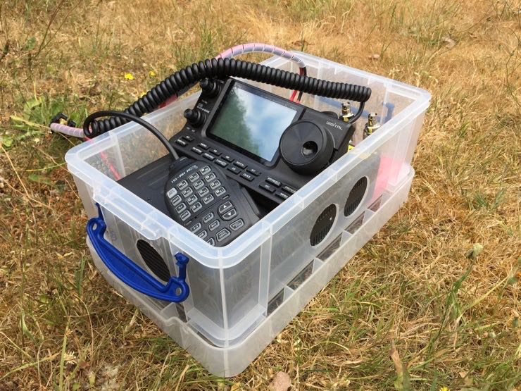
Fast forward to this week when I discovered that the IC-7100 base unit will also fit inside a 5 litre XL storage box made by Really Useful Boxes:
http://www.reallyusefulproducts.co.uk/usa/
http://www.reallyusefulproducts.co.uk/uk/
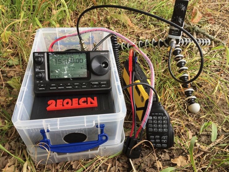
The XL version of the 5 litre box has a taller lid, and as you can see from the accompanying photos, accommodates the base unit with the head unit sitting on top of it in a ready to use configuration. The tolerances for height are also exact, the VFO knob very lightly touches the lid, so don’t put something heavy on the box:
Once the lid has been removed, the radio can operate directly from the container:
To make the whole thing fit, I used a 25cm CAT 6 cable in place of the original connection cable and a significantly shortened power lead. As luck would have it, I created the shortened power lead a while ago because I often put the battery right next to the radio.
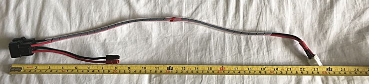 You can see that I removed a section between the power plug and the fuses, and now use the removed length as an extension should the battery be further away. Although it wasn’t my intention at the time, the main part is about 2 feet long, the secondary about 8 inches.
For transport, the power cable is coiled behind the head unit, ensuring the fuse holders sit in the void immediately behind it, while the microphone cable is coiled on top leaving the microphone resting inside its own coil. You can see the arrangement below:

In the next photo, you can see how the cabling emerges from the back of the base unit:
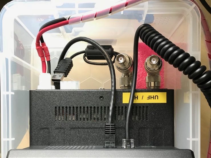
There’s just enough space for the power cable to leave the base and bend around without undue pressure, and likewise for the CAT 6 cable to curve round into the back of the head unit. Two angle connectors make the antenna ports accessible from above, while a short USB external drive cable provides access to the USB port for data modes and CAT control. A longer USB extension cable is attached to this short cable only when required, and the extension uses much more substantial ferrite chokes to mitigate noise from the computer.
To complete the transport package, I’ve cut out a kaizen style foam insert to make sure the base unit can’t move back into the cabling space, and another to make sure the head unit doesn’t slide towards the front.
The last problem of course is cooling. The fan is located in the front of the base unit, with slots along the sides and top to allow air flow. The box unfortunately is exactly the right size for the base, leaving no gaps for air to circulate. In the absence of a proper workshop or professional tools, I opted to use a hole cutter designed for putting pipes through wood panels. It turns out that plastic has a tendency to deform rather than cut under the blades due to friction heating. A sharp knife was essential in dealing with the effects of that deformation to produce the final smooth edges around the holes:
While I’m happy with the port exposing the front fan, the two holes on each side do not completely expose the side slots. Do I drill out the space between them knowing how tricky and flexible the plastic can be, and would a larger hole compromise the strength of the box? For now, I’m going to keep a careful eye for any temperature issues.
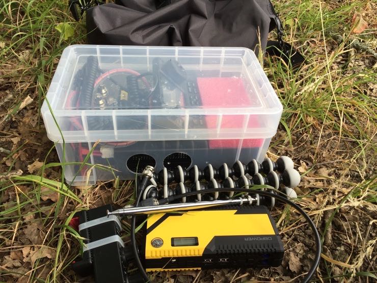
The current arrangement is to carry the box horizontally in a cheap travel bag:

Could the box be tilted vertically with the base unit nose down and carried in a back pack for longer excursions? Yes, but experience has told me that the lid latches on Really Useful Boxes have a tendency to pop open when you do that, so a luggage strap around the box may be required to prevent its very expensive cargo from spilling out. I’m also mindful that the box lid gently touches the VFO knob, so might put load on it in the vertical position.
The final result is something of a Swiss watch, and there isn’t much room for error. Things have to be arranged ‘just so’ to fit, but it does mean I can pack and pick the whole thing up in a handy container. The radio only needs a battery and antenna to be connected on site and then it’s ready to go.
There’s something oddly satisfying when unrelated objects come together like this. Who knew that this box was just the right size to fit the radio?
So, what do you think?
Thank you for sharing this project, Mark!
I love your Micro Go-Box: it’s practical, affordable and makes an otherwise awkward field radio easy to deploy and use. Looking at your photos, I realize that the IC-7100 does have one strong suit for field use. The IC-7100 front panel is tilted at a very comfortable 45 degree angle for use.
Post Readers: What do you think? Any other IC-7100 owners out there who take their rig to the field? Please comment!