Shortwave listening and everything radio including reviews, broadcasting, ham radio, field operation, DXing, maker kits, travel, emergency gear, events, and more
Many thanks to SWLing Post contributor, TomL, who shares the following guest post:
Summer Daytime DXing 2019
by TomL
I took note of the mediocre band conditions this summer amongst amateur radio operators as they were making off the cuff comments about still being in a solar minimum. Some had gone out and bought upgraded transmitters to solve the problem (MOAR WATTS!). And more power thrown at a weak ionosphere does seem to help get a signal farther. I had not been out since the spring and decided to find out for myself. But instead of more watts, I wanted more height.
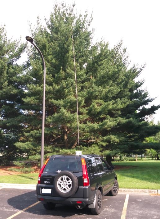
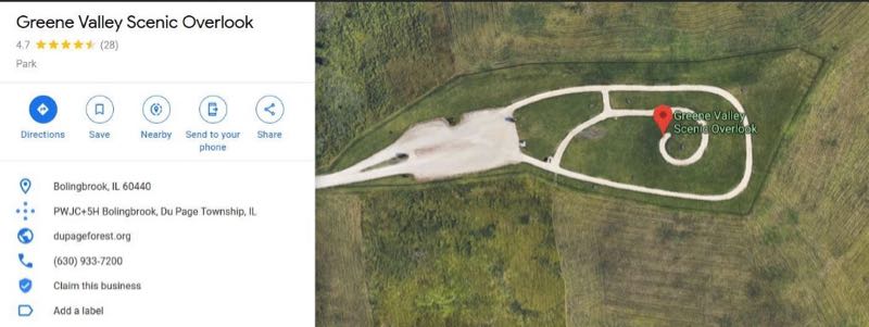
Greene Valley Scenic Overlook is open to the public from May through October on weekends only (and only from 11am-6pm). It was the largest land fill (aka, garbage dump) in Illinois, now covered over and producing captured methane gas. On August 3 & 4, I ventured over there to see if its 190 feet above the surroundings might help my radio reception.
After trying my luck with a 12 foot vertical antenna on a tripod (and numerous children running around it chasing butterflies or looking at the view of Chicago), I went out the next day and parked away from anyone and put up my 19 foot vertical on the roof of the car. This setup is still amazing to me and works much better than the tripod mounted antenna, probably because it has a proper ground plane as well as being 7 foot taller.
So, yes, the conditions were so-so, not too bad and not too good. Lots of weak signals and some empty frequencies that I had expected to hear some South American stations around the 5 – 10 kw range. Weak stations from Asia were more scratchy sounding than usual even with the extra 190 feet of height. Here are 5 broadcast recordings as a sample (times in UTC):
Running out of things to listen to, I wandered over to the 20 meter amateur radio band and found a different situation. Propagation was decent between the Western hemisphere and Europe. Lots of “pile ups” going on with people trying to make contact with their trans-Atlantic counterparts. Some said they were running 500 watts or more, so more power does seem to help! Here are 5 recordings to show how active it was:
This outing was quite educational and I find it curious that people running 1000 watts or less are able to be heard well between continents but the large broadcasters were difficult to hear. Antennas pointed in the right direction, at the right time of day and frequency, can certainly do amazing things, plucking those weak signals out of the air so easily. And I do think the extra height had something to do with hearing this magic, too!
Happy Listening,
TomL
NOTES:
An easy way to lookup amateur radio operator “call signs” is to go to web site QRZCQ.com which does not need a login. Some records may be out of date, but most of it is accurate.
Setup used was a cheap Dell laptop, Windows 10, SDR Console 3.03, connected to the AirSpy HF+, a Palstar amplified preselector, and an old Kiwa BCB filter, then going up to the car roof magnetic balun (a Palomar MLB2) which is then connected to the 4 magnet base and the MFJ 19 foot stainless steel antenna. You can read about it here:
Brilliant report, Tom! It’s true: the bands are fickle, but like you I always find interesting things to hear on HF. I think your setup using your vehicle as the ground plane for the antenna is a fantastic idea. Plus, set up is easy, self-supporting, and you’ll never have to worry about a park ranger, for example, complaining because you have a wire suspended from a tree. And when there are no trees? You’re still golden.
Thanks for sharing your experience and DX! Amazing that even with mediocre conditions, you still snagged some distant signals.
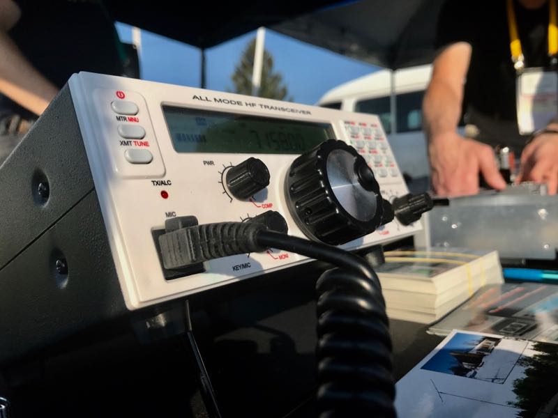
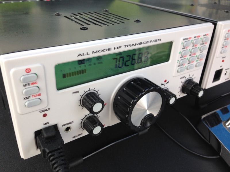
Since last year, I’ve been in touch with Boris, and we arranged to meet again at the 2019 Hamvention so I could take a closer look at the RGO One, especially since he has started shipping the first limited production run.
The RGO One delivers everything Boris promised last year and Boris is on schedule, having finished all of the hardware design and having implemented frequent firmware updates to add functionality.
Excellent first impressions
I’ll be honest: I think the RGO One was one of the most exciting little radios to come out of Hamvention this year. Why?
First of all, in contrast to some radios I’ve tested and evaluated over the past two years, I can tell immediately that the Mission RGO One was developed by an active ham radio operator and DXer.
QRP/QRO output 5 – 50W [can actually be lowered to 0 watts out in 1 watt increments]
All mode shortwave operation – coverage of all HAM HF bands (160m/60m optional)
High dynamic range receiver design including high IP3 monolithic linear amplifiers in the front end and diode ring RX mixer or H-mode first mixer (option).
Low phase noise first LO – SI570 XO/VCXO chip.
Full/semi (delay) QSK on CW; PTT/VOX operation on SSB. Strict RX/TX sequencing scheme. No click sounds at all!
Down conversion superhet topology with popular 9MHz IF
Custom made crystal filters for SSB and CW and variable crystal 4 pole filter – Johnson type 200…2000Hz
Fast acting AGC (fast and slow) with 134kHz dedicated IF
Compact and lightweight body [only 5 lbs!]
Custom made multicolor backlit FSTN LCD
Custom molded front panel with ergonomic controls.
Silent operation with no clicking relays inside – solid state GaAs PHEMT SPDT switches on RX (BPF and TX to RX switching) and ultrafast rectifying diodes (LPF)
Modular construction – Main board serves as a “chassis” also fits all the external connectors, daughter boards, inter-connections and acts as a cable harness.
Optional modules – Noise Blanker (NB), Audio Filter (AF), ATU, XVRTER, PC control via CAT protocol; USB UART – FTDI chipset
Double CPU circuitry control for front panel and main board – both field programmable via USB interface.
Memory morse code keyer (Curtis A, CMOS B); 4 Memory locations 128 bytes each
What really sets the Mission RGO apart from its competitors is the fact that it’s compact, lightweight (only 5 lbs!), and has a power output of up to 50 watts. Most other rigs in this class have a maximum output of 10 to 15 watts and require an external amplifier for anything higher.
The RGO One should also play for a long time on battery power as the receive current drain is a modest 0.65A with receiver preamp on.
The RGO is also designed to encourage a comfortable operating position. The bail lifts the front of the radio so that the faceplate and backlit screen are easily viewed at any angle.
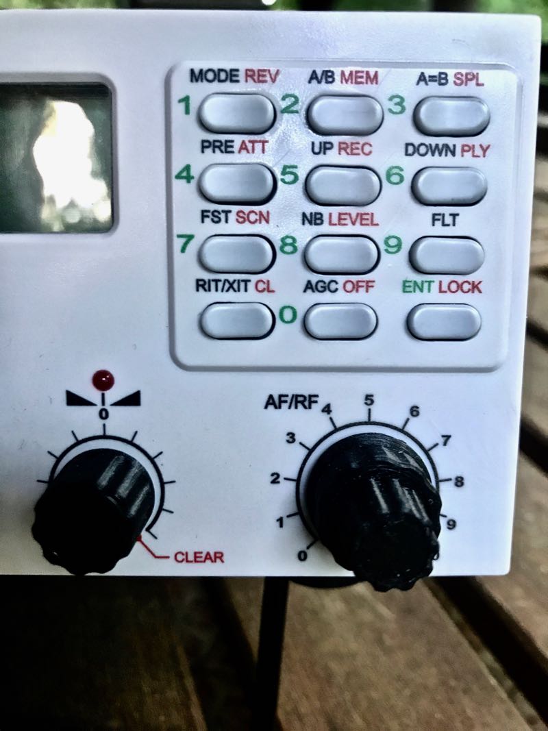
The keypad is intuitive and–hold your applause!–all of the important functions are within one button or knob press!
The front panel design is simple and clean. There are no embedded menus to navigate to change filter width, power level, RF gain, keyer speed, mic gain, pre amp, or audio monitor level. Knob spacing is excellent and I believe I would even be able to operate the RGO while wearing gloves.
Even split-operation is designed so that, with one button press, you can easily monitor a pile-up and position your transmit frequency where the DX station last worked a station. (This is similar to the Icom XFC button). The user-interface is intuitive; it’s obvious to me that Boris built this radio around working DX at home and in the field.
Speaking of the field…
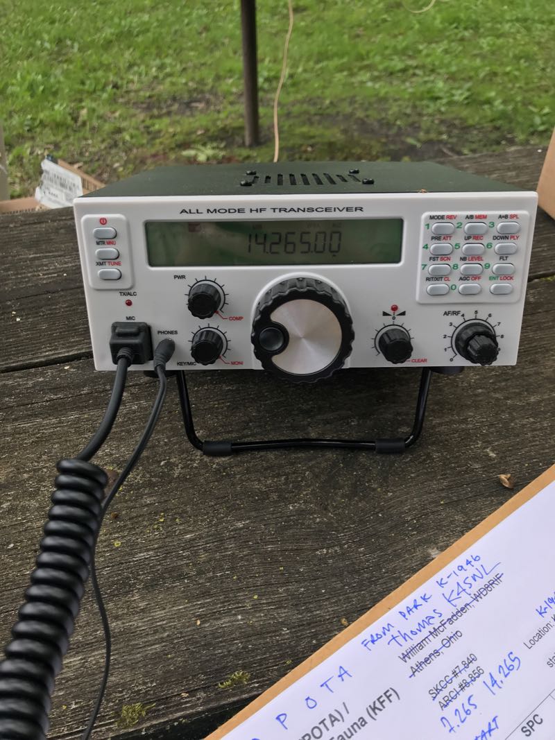
Parks On The Air (POTA) with the Mission RGO One
At my request, Boris has kindly loaned me one of the first production run units to test and review over the next few months. I intend to evaluate this radio at home, in the field, and (especially) on Field Day. By July, I should have a very good idea of how well this Bulgaria-born transceiver performs under demanding radio conditions!
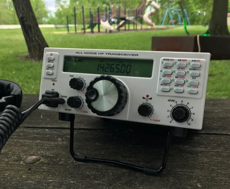
I had planned to begin my RGO One evaluation after returning home from Hamvention, but I couldn’t resist taking it to the field, even though the propagation forecast was dismal.
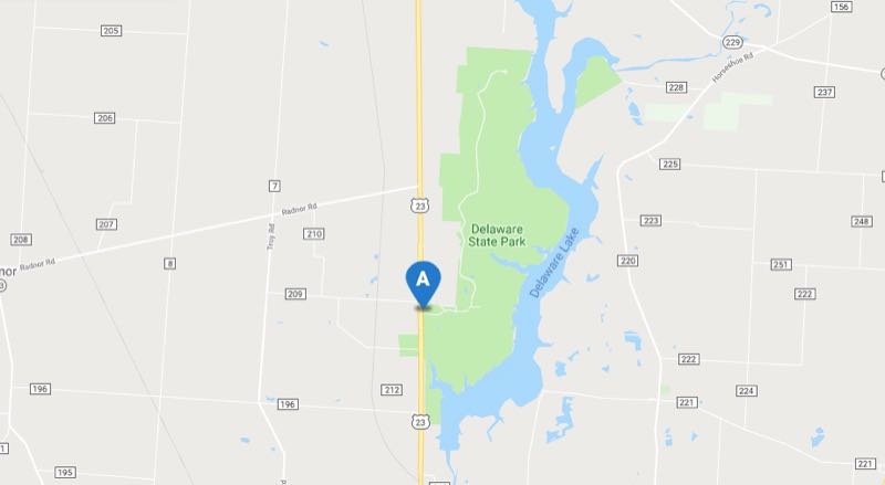
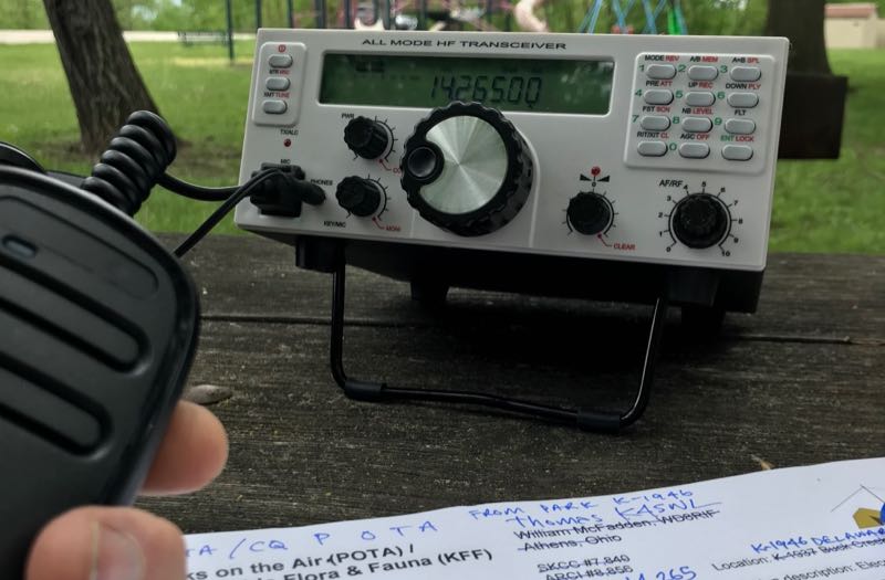
The first leg of my journey home from Hamvention took me to Columbus, Ohio, on Monday, so I scheduled a Parks On The Air (POTA) activation of Delaware State Park, K-1946.
Delaware State Park (POTA K-1946) in Delaware, Ohio.
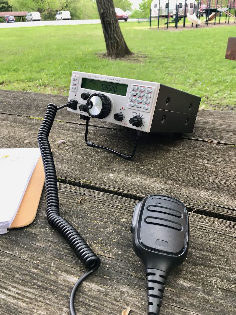
My buddy Miles (KD8KNC) and I met our mutual friend Mike (K8RAT) at the park entrance and quickly found a great site with tall trees, a little shade, and a large picnic table.
We set up the RGO One and, for comparison, my Elecraft KX2 for the POTA activation.
I won’t lie: band conditions were horrible. Propagation was incredibly weak, QRN was high, and QSB was deep. Yuck!
Still, this activation gave me a chance to test the RGO One in proper field conditions.
I was limited to SSB since the only CW key I had with me, the paddle specifically designed to attach to the front panel of the Elecraft KX2, wouldn’t work with the RGO One. In addition, I was limited to 25 watts output because the antenna I deployed, the LnR Precision EFT Trail-Friendly end-fed antenna, can only handle power up to 25 watts.
Although I had never operated the radio before, I was able to sort out most of its functions and features quickly.
The receiver audio was excellent and the noise floor seemed quite low to my ears. The internal speaker does a fine job producing audio levels that are more than ample for a field setting. Still, I prefer operating with a set of earphones in the field–especially important on days like this when propagation equates to a lot of weak signals.
Although I failed to make a total of ten contacts to claim a proper POTA activation, I was pleased with offering up K-1946 to seven lucky POTA hunters/chasers. I simply didn’t have enough time available to work three stations more at such a slow QSO rate.
Of course, my signal reports were averaging “5 by 5” and were never more than “5 by 7” regardless of which rig–the RGO One or the KX2–I was using. The reports on the RGO One transmit audio reports were great.
Stay tuned!
I will publish my first review of the Mission RGO One in The Spectrum Monitor Magazine, most likely in August or September. In the meantime, I will post updates here as I put the RGO One through its paces. I’m especially excited about using it during Field Day with my buddy Vlado (N3CZ) to see how it holds up in such an RF-dense environment.
And now that the POTA bug has bitten me? Expect to catch me on the air with the RGO One over the next few weeks!
If you’re interested in following the Mission RGO One, bookmark the tag: RGO ONE.
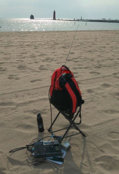
Many thanks to SWLing Post contributor, TomL, who shares the following guest post as a his Backpack Shack 3 continues to evolve:
Backpack Shack 3.0 – Part 3
by TomL
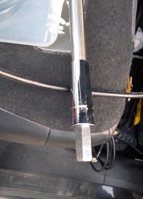
I have now gone overboard since I think bigger must be better. The temptation was just too great and now there is an MFJ-1979 17-foot telescoping whip antenna in my car (with consequences).
MFJ Angst
I have a love/hate relationship with MFJ products because of what I think are useful ideas that are made somewhat poorly. But I went ahead and bought the large whip since I figured they could not possibly screw up something so simple, right?
Wrong. As I excitedly tried to screw the supposed 3/8”-24 threaded end into the nice standard Firestik K-11 magnet mount, I realized I was turning and turning it but it was not going in!!! I even had a small steel sliver of metal sticking into my flesh to prove I was not dreaming. The previous day, it had screwed in very tightly, but it did screw in. So, there I was after a long day of work, ready to listen to some SWL-Nirvana and I could not get the blasted antenna into the mount–? That Firestik mount is a VERY standard 3/8”-24 female thread and the other third-party antenna shafts fit perfectly and easily EVERY time I use them. I hate $60 of poor workmanship and MFJ seems to be the poster child of overpromising and underdelivering.
I was determined to make this work, by force if needed. One of the Trucker antenna shafts by necessity had an extra coupling nut on it to allow the extra 18 inch shaft to connect, so I took it off there and tried to thread it onto the MFJ-1979. It barely moved. Not to be thwarted, I dug out an adjustable wrench and 3/8” socket wrench with ½” socket and grunted and twisted and tightened until the coupling nut was threaded all the way “up its shaft”. That is what I feel like telling MFJ! That coupling nut is never coming off and now that I truly have bought it and cannot return it, I might as well use it.
The stainless steel telescoping rod is extremely thin and feels like it can bend and dent with any kind of mishandling. So it resides collapsed in a 27 inch PVC pipe with plumbing pipe foam inside to baby it when it is not being used. It remains to be seen if I can remember to “Handle With Care” when extending/collapsing it. We’ll see.
Ready-to-go
OK, so using the 18 inch antenna shaft attached to the magnet mount, then the coupling nut on the MFJ antenna, I extended it to a total of about 13 feet. With the DX Engineering Pre-amp turned on, and using the SDR Play RSP2, I was getting many signals booming in. All the usual names we are familiar with – RMI, CRI, Turkey, Cuba, etc. But also the noise level was very high. I know it is summer but I may have been overloading the Pre-amp a little bit. Here is an example, Radio Progresso from Cuba with some very nice acapella music but also a noisy background (plus, a noisy laptop computer pulse!):
So I decided to come back in the morning before my workday started and see if the static crashes would have died down.
Preamp Angst
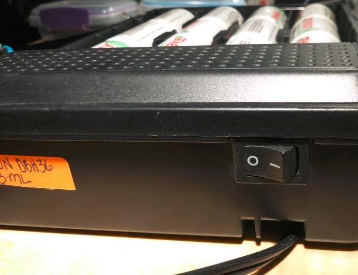
The next morning I had everything hooked up again in the same spot at the Forest Preserve (located in a suburb of Northern Illinois). I moved the Cross Country Preselector to be directly connected from the roof, then to the antenna switch on the “Breadboard” (see part 2) to better prevent overloading. I turned on the Verizon battery pack and nothing. No Pre-amp light. Switched it on, off, on, off – nothing. So, I thought I must have burnt it out the previous session?
Later on, I found it was some sort of short in the switch and I will have to move the D-cell batteries to a backup battery pack. In the meantime, I had to do without the Pre-amp and was forced to extend the MFJ antenna all the way. With the 18 inch extension attached to the magnet mount, that was a total of 18.5 feet from antenna tip to the top of my car roof.
This was actually fortuitous since I was already concerned about overloading the Pre-amp or perhaps amplifying background noise. This forced me to test it in a more “barefoot” manner, hearing what it would natively hear without any Pre-amp. It was also lucky there was no wind to blow it over! It seems that if one is in an RFI-quiet area with decent view of horizons, the 20+dB Pre-amp may not be needed, depending on frequency band involved.
I have read that “Norton” style 10 dB Pre-amps and custom handmade transformer baluns are used by Dr. Dallas Lankford in his Low Noise Vertical antennas. I don’t want to get into winding baluns so I am using one Palomar Longwire Balun to simulate the “magnetic” transfer. His design uses two, one 10:1 at the antenna and a 1:1 balun at the feedline into the house. For more reading on LNV antennas, see these references:
I purposely monitored Voice of Korea for their news statement on the De-Nuke talks on the 25 meter band and found it came in great, just as many others have heard it. This was encouraging. Examining carefully the Data file from the SDR, here is what I pulled from it. I am pleasantly surprised and happy with the results; some stations I had never heard before and the language and music are very exotic. All of it was a little more than one half hour of recording time (14 June 2018, 1300 UTC). You may have to crank up the volume on the weaker recordings to hear those properly.
Recordings
(Station, Frequency, Language(s), Transmitter site from www.short-wave.info):
Voice of Vietnam, 12020 kHz, English, Hanoi Vietnam (with local UFO noises near me)
Taiwan International, 11640 kHz, Chinese, Kouhu Taiwan (blasting in strongly plus strong echo of broadcast at top of the hour – is a second transmitter signal going around the earth the other way and getting to me??)
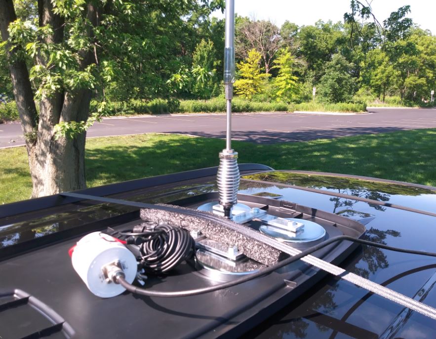
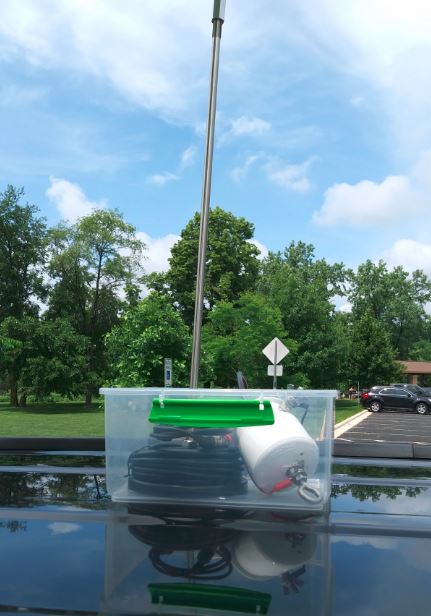
Eighteen feet of whippy rod can sway in the gentlest breeze (consequences of “bigger must be better”). The described setup has fallen over in as little as a 12 mph sustained wind when fully extended because I had the base in a plastic box. I want plastic under the magnet(s) in order to get it off easily and put away out of sight! Now installed is a larger QUAD magnet mount for better stability:
I am using the flat plastic lid from a 20 gallon tote container under the quad mount and a mover’s tie down strap to the main bar of the quad (I have room for multiple straps if needed). Ten foot fits just fine:
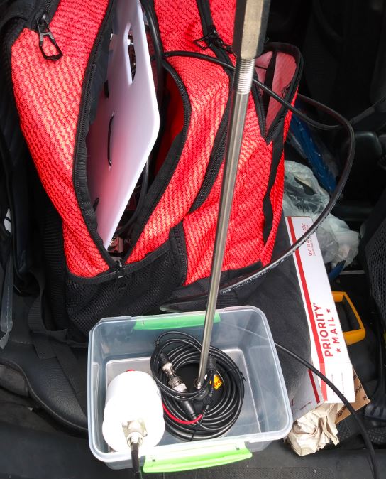
Because the backpack and quad mount can fit inside the 20 gallon tote container, this setup can be attached to a picnic table in a state park or campsite if I choose. The Firestik single magnet mount will be recycled as a VHF antenna mount. I can go virtually anywhere now.
Instead of the 20+dB DX Engineering Pre-amp, perhaps one of those “Norton” 10 dB Pre-amps might be optimal (Kiwaelectronics.com broadband-preamp). And I need to figure out why my Verizon battery pack failed as each Tenergy D cell measured fine. Oh yeah, I have to buy an extra coupling nut, too……
Happy Listening,
TomL
Thanks so much for sharing this latest iteration of the BackPack Shack 3.0, Tom! It seems to me, as you imply, your current setup could be installed pretty much anywhere.
I’m sorry to hear about your troubles with MFJ. I’ve only had good experiences with them in the past, but I suspect the specs on the 3/8”-24 thread were simply incorrect or perhaps metric and mislabeled.
Post readers: Read Tom’s past contributions and articles by clicking here.
Click here to read Backpack Shack 3.0 – Part 1 and Part 2.
Many thanks to SWLing Post contributor, TomL, who shares the following guest post as a his Backpack Shack 3 evolves:
Backpack Shack 3 – Part 2
by TomL
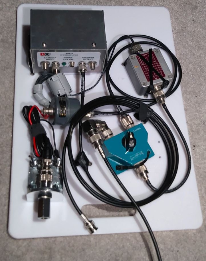
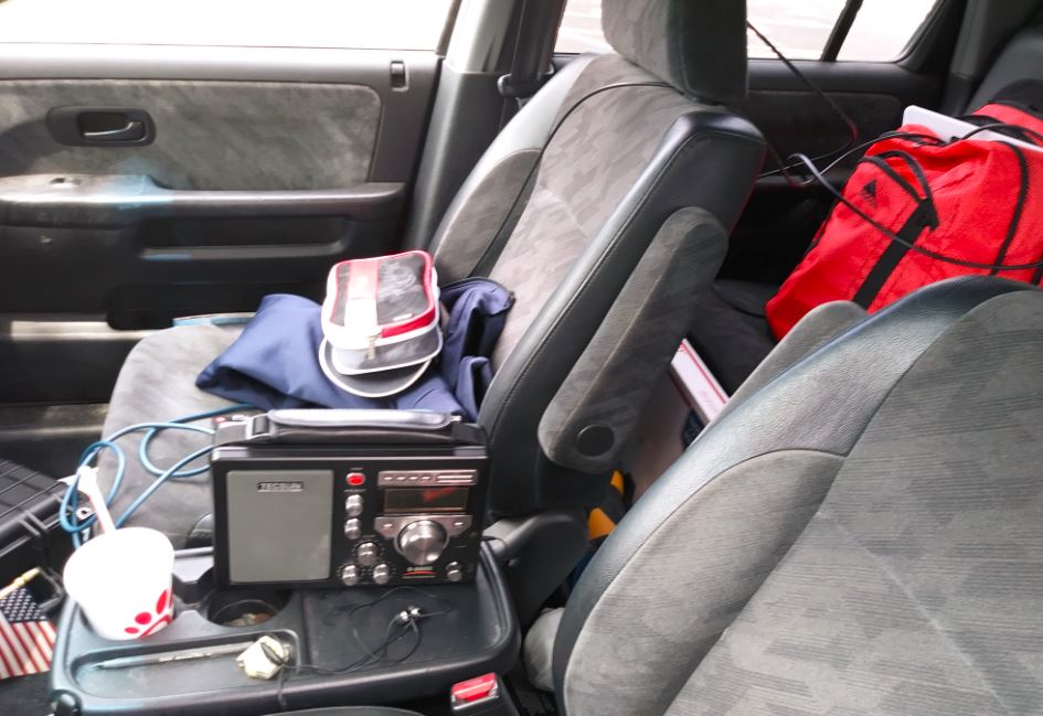
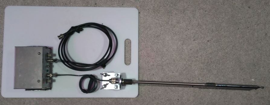
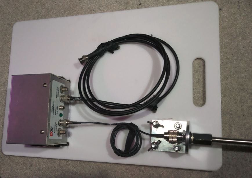
Wanting MOAR options for my recent amplified whip antenna experiment, I decided to add a second antenna input to the kitchen cutting board (can I call it a “Breadboard”? – Ha, that’s an electronics joke!). The idea behind it came from realizing that I might not want to spend all my time outside at a picnic table or on the beach, especially if it is drizzly and windy. And I still wanted a better ground for the antenna. So, I thought I could use more Trucker Parts and put an antenna on top of the roof of my vehicle so I could listen in the relative comfort and safety of my small SUV (or even a friend’s car).
Breadboarding
Here is the crowded “Breadboard” with some extra items added.
I thought of the vertical antenna as a short longwire and had an old, original RF Systems Magnetic Longwire Balun. That device allows for an improvement in signal/noise ratio (in theory) if used on a longwire. Perhaps it works on this, too?? You can see the gray cylinder connected right beneath the trucker mirror mount on the left (this will not be tested at this time, see External Antenna below). The output goes to a greenish Daiwa switch on the right.
A large amplified antenna has the real possibility of overloading the amplifier. With the Magnetic Balun, I am hoping the VHF band is attenuated enough to preclude any problems because its response naturally tapers off past 40MHz. But Mediumwave is well within its bandpass. I remembered an old Kiwa Electronics Broadcast Band Rejection filter not being used for a long, long time, so I connected that right after the Daiwa switch (the metal box with red plate).
This output then goes to an RF choke just before entering the pre-amp. I figure I will be using my SDRPlay RSP2 and noisy laptop and wanted to try to reduce any interference traveling on the outside coax braid before it gets amplified.
External Antenna
OK, now for the other Daiwa switch selection. The external antenna will be connected and disconnected as often as I use it. I attached two right-angle coax adapters to be the connection point for the antenna. This is so that the physical switch threads do not have to handle that wear-and-tear. You can see it as the fuzzy out of focus thing sticking up out of the left side switch position.
The wire going out the top of the Breadboard goes to a Firestik K-11 magnetic mount placed on top of the roof of the SUV. I also wanted this to be connected to a magnetic balun. I just happened to have a nearly unused Palomar Engineers Magnetic Longwire Balun. It has its own ground lug for use with a counterpoise. Temporarily, I left the 18 feet of wire that came attached to the K-11 Mount and attached an adapter and BNC test lead; on the other end is connected the spade lugs to the Balun (red wire to the lanyard nut, black wire to the ground lug). It all fits neatly inside a Sistema 3 liter container.
The magnet and box self-clamp easily onto the roof of the vehicle. I added a new 18 inch section to the Trucker Antenna Shafts creating a full 72 inch antenna, complete with mag mount, ground plane (car body), and magnetic balun. It is very easy to put up and take down and the box helps keep everything contained.
I am pushing things a bit here. Magnetic Baluns are not really meant to be used on vertical antennas. It probably breaks some sort of Cosmic Electrical Law somewhere that causes electromagnetic waves to get very confused and die a horrible, twisted, circular death. But I figure that it is an unbalanced “line” similar to a longwire antenna; it’s just a little short and goes straight up instead of horizontal! I like the idea, so I am going to run with it.
Warnings!
It goes without saying that the Antenna Shafts, magnet mount, and magnetic balun are weatherproof (but NOT lightning proof!). Take proper lightning precautions and take it down. Even so, I might add a small drainage hole to the box since it did rain a tiny bit during testing.
Secondly, this setup is ONLY FOR STATIONARY VEHICLES!!!! DO NOT TRY TO DRIVE DOWN THE ROAD OR HIGHWAY!!!! The magnetic mount will NOT stay on the car and will damage your vehicle and maybe a vehicle travelling next to you!
Performance
As you can see from the picture, my new Tecsun S-8800 is getting a workout while connected to the Cross Country preselector (not shown behind it) and to the backpack next to the back seat window. The Tecsun S-8800 is a nice radio. My copy has a couple of quirks that I might have to send it back (the AM band tunes incorrectly 2 kHz lower than it should and the SW SSB tunes 140 Hz higher than indicated and I have to compensate using the fine-tuning dial for these modes–FM seems correctly tuned).
Other than this, the actual performance is really quite good! DSP does have sharp cutoffs to the IF bandwidth (especially resolving strong station interference when selecting 3 kHz vs. 4 kHz). With all my filters/balun/choke, I did not notice any MW or FM breakthroughs and signals on those bands were nicely contained and “normal”. Interference from my cell phone while looking up internet frequency listings was minimal – seems like the cable shielding, choke, and car roof are doing a good job.
The audio output jacks have very thin clearance between the jacks and the housing of the radio. So for the second time, I will not have recordings since the cable I wanted to use has home theater style construction with very thick plug outer connectors and will not fit!
From an RF-quiet “Forest Preserve” (County park), there were a variety of stations received from the 25 through 19 meter bands (Local time 11am-1:30pm). A few stations I have never heard before until now:
Radio Free Asia in Korean on 11985 KHz (Tinian Island)
Radio China International in Esperanto on 11650 KHz (Xian China)
Radio Farda in Persian on 12005 KHz (Wooferton England) – broadcast opposite my direction
Radio Bible BCI in Somali on 15310 KHz (Nauen Germany) – Strange sounding but interesting Christian Somali music
Radio Free Asia in Chinese on 13675 KHz (Dushanbe Tajikistan)
Voice of Hope Africa in English on 13680 KHz (Lusaka Zambia) – had to use ECSS USB to get away from strong interference from RFA on 13675, fairly good intelligibility (including music)! I wish there was a 6 KHz option for SSB mode since the audio was slightly muffled and could not compensate much with the tone controls. That kind of feature usually comes with radios costing 3X more, however.
Voice of Korea in French (Kujang North Korea) being squashed by Radio China International (Kashi China) in English on 13760 KHz
It was so nice not to be on a beach and have people walk by STARING at me with my weird radio/antenna setup. And I was dry and comfy sipping a cool drink while there was a drizzle of rain pelting the windshield. Downside might be that the car setup cannot always be located optimally if I want to be next to that Very Large Body of Water (Lake Michigan) to help enhance reception but this is not a bad alternative. The next test will have to be during early evening when signals are booming into my location and see if performance holds up under those conditions!
As always, Tom, a most impressive setup powered by home-grown ingenuity! Thanks so much for sharing the evolution of your field kits with all of us here at the SWLing Post!
By the way, you still have me chuckling about your use of the term, “breadboard!” 🙂
Many thanks to SWLing Post contributor, TomL, who shares the following guest post:
Backpack Shack 3 – Amplified Whip Antenna
by TomL
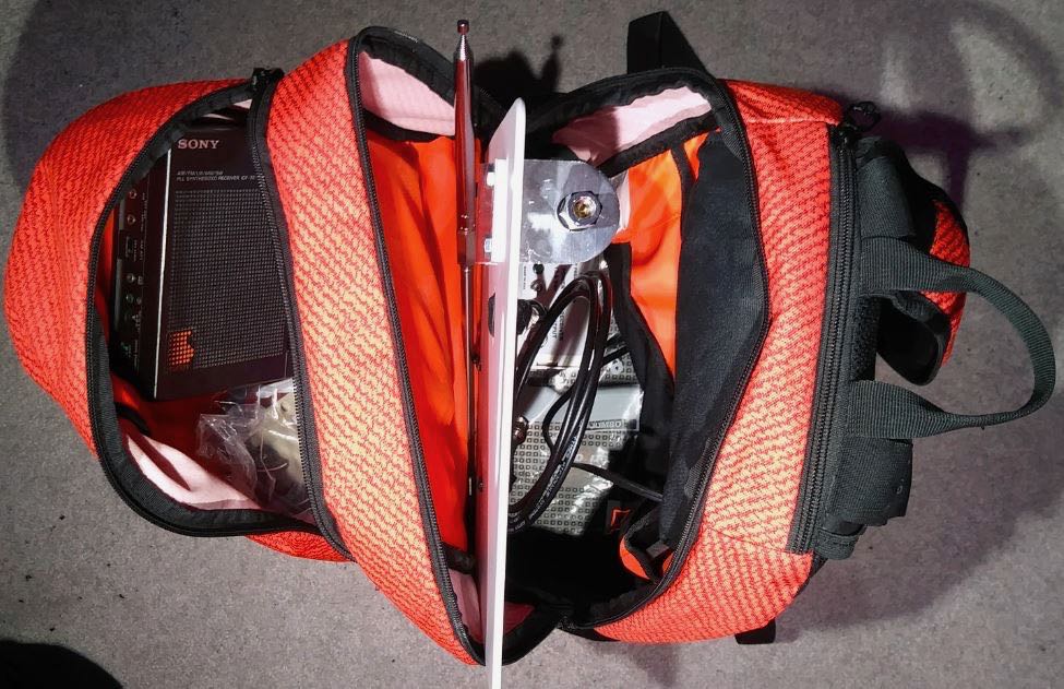
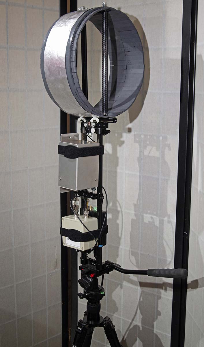
So, having enjoyed using the Ferrite Sleeve Loop I created last year, I have wanted something a little more sensitive and less bulky. I will eventually create a much BIGGER FSL antenna on the order of 2 feet long and perhaps 18 or 24 inches in diameter for indoor/attic use. But that is not a priority at the moment.
Since I already have the DX Engineering Pre-Amplifier and the very nice Cross Country Preselector from the loop project, I thought it might be useful to create an active whip antenna for it. And the cool looking Solar Red backpack needed something to do!
Power
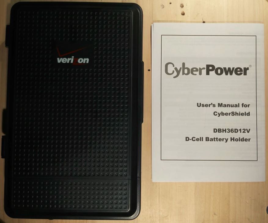
Now that the bulky loop was not taking up the main compartment of the backpack, I could think about what else to put in there, like a larger power pack. I scoured FleaBay for ideas and stumbled upon this contraption for backup power to network systems, the CyberPower CyberShield for Verizon.
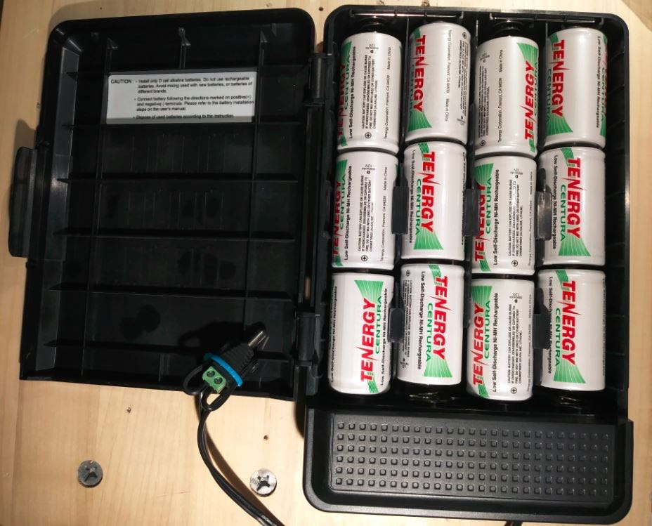
This has 12 spaces for D-cell batteries and was mounted inside the demarcation terminal to provide backup power for things like cable systems and Copper-to-Ethernet networks. It is not waterproof, so would be inside the premises of the customer getting the internet/cable service. But my Pre-Amp needs 12-18Volts and would love to have nearly unlimited power. So, I bought a used one, cut the end off of the power lead and put on my own 2.1×5.5mm plug (carefully glued down and tie-wrapped). Then I filled it with 1.2Volt Tenergy D-cells.
Everything was just fine until I forgot to double check the polarity of the plug that I had wired onto the end. Plugged it into the DX Engineering Pre-Amp, flipped the power switch and fitzzz…. The Pre-Amp light went on, then off (permanently!).
So, my expensive mistake is that I start using the FREE multimeter I got from Harbor Freight and check the polarity before I connect homemade battery packs to anything!!
DX Engineering charged me $60 to fix my mistake and it is working fine now after I swapped the wires on the plug. Yes, their Pre-Amp is NOT reverse-polarity protected! Disappointing, since the price tag for that device is $148!!! The CyberShield now sits comfortably inside the bottom of the backpack.
Antenna
Now that the drama was over regarding the Power pack, I could think about the whip. I did not want a wimpy whip! (No one should rightly aspire to this, in my opinion). More FleaBay searches found me looking at Trucker parts. Loaded whips, magnetic mounts, 10 foot tall MFJ telescoping whips, etc was looking a bit expensive.
Besides that, I cannot fit a 10 foot tall telescoping whip into the backpack, I am limited to at most 18 inches (and that is at an angle to fit it in there). But I found an old-fashioned mirror mount that looked promising since it had a nice SO-239 connector at the bottom and standard CB antenna fitting on top of 3/8”-24.
Then I found the 44 inch SuperAntenna with the same threads; then found the replacement Stainless Steel Shafts for a Wilson antenna in different lengths (I ordered the 10 inch version to test). With a couple of rod coupling nuts and I was ready for testing!
Test Locations
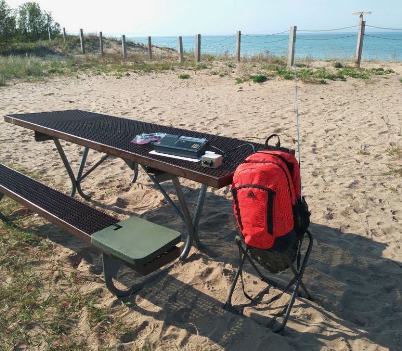
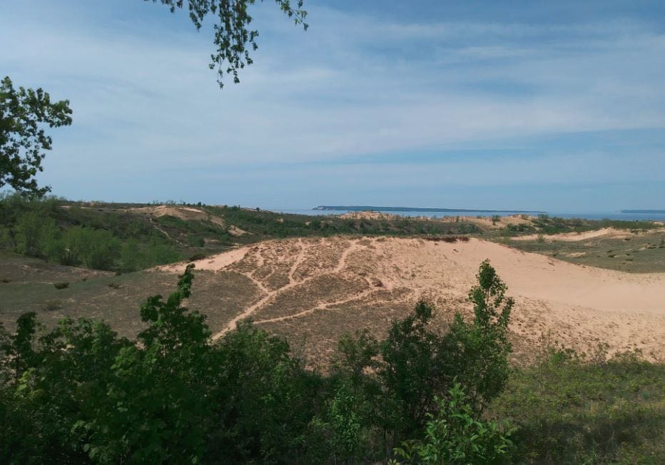
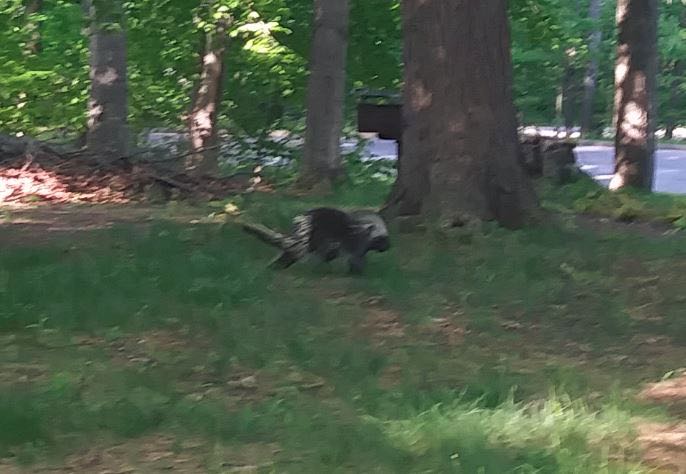
I had already scheduled a short vacation to Sleeping Bear Dunes on the thumb of Northwestern Michigan, so I took this test setup with my Sony ICF-2010. This area is a very nice remote National Lakeshore with minimal noise. I tried a beach setting and a couple of hilltop picnic areas (including meeting a local Porcupine) and had very nice reception at all locations. The hilltop locations are approximately 400 – 600 feet above the Lake (yes, the Dunes are THAT big there!).
Meeting a local Porcupine
Later on, I went to Grand Haven, MI on the way home and stopped at their very lovely beach.
Reception was just as good as the hilltop locations at Sleeping Bear! In both areas, I was next to a large body of water (in this case, Lake Michigan) and makes for an advantageous place for DXing! I had also stopped at a Rest Area off the highway and that was a terrible place even though it was electrically quiet but nowhere near the big Lake. I guess the rumors are true about being near a large body of water somehow enhances reception of weak signals–?
I will submit recordings later since I lost the mini-B cable for the Sony digital recorder and had to order a replacement. However, this was a nice project that freed up some space inside the backpack. I will add an 18 inch extension to the whip that will give me a total length of 72 inches. Plus, it is mounted 12 inches up on the poly cutting board and I place the backpack on a small hunters folding chair that is about 24 inches tall. So, the tip will be about 9 feet off the ground.
Not pictured but I was also able to easily fit inside a used CCrane Twin Coil Ferrite antenna for mediumwave use that also performed very well. I noticed that the picnic benches at some locations are made of metal, so that gives me a future idea of trying to leverage that to use as a ground plane somehow. The battery pack is heavy but also gives great ballast to the backpack and will not tip over. Cannot wait for the Tecsun S-8800 to arrive so I can try leaving the radio inside the bag and just use the remote control to tune!
As always, I’m so impressed with your spirit of radio adventure, Tom! I love the fact that your goal is to make a field-deployable DX kit that isn’t cumbersome or time-consuming to set up on site. I imagine you only need a couple of minutes to open the pack and have it on the air.
Those DXing spots are stunning! I had no idea one could find 400-600′ dunes in NW Michigan–! With that said, I’ve heard that part of the state is one of exceptional natural beauty. If you could somehow turn the lake into a body of salt water–thus increasing ground conductivity–you’d really enhance that already impressive reception! I’m guessing that sort of project would be a bit outside your budget! Ha ha! That and the freshwater fish might protest!
To me, there is no better way to enjoy radio than finding a nice RF quiet spot in the great outdoors…no matter where you live in the world. On top of that, Tom, you’re constantly building, experimenting, documenting and sharing your findings–you’re a true radio zealot! Huzzah!
Post readers: Read Tom’s past contributions and articles by clicking here.
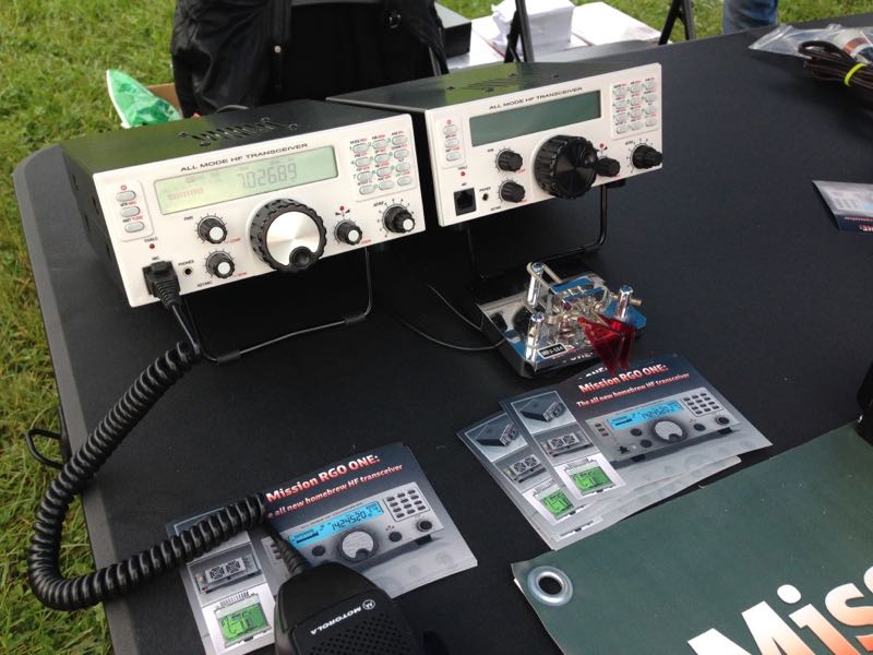
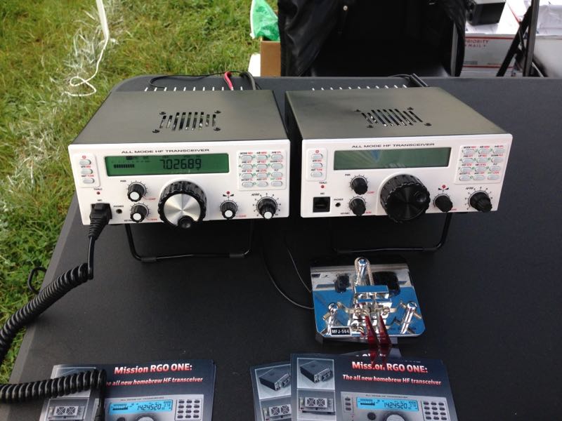
I found this cool tabletop transceiver in the flea market area of the Hamvention early Saturday morning and included it with my inside exhibits photos. I wasn’t able to gather a lot of information from the representative at the time because the Hamvention staff opened the gates to general admission a full 30 minutes early, so I had to make a sprint to my table at the other side of the fairgrounds.
The following specifications/features were listed on the RGO ONE product sheet:
QRP/QRO output 5 – 50W
All mode shortwave operation – coverage of the 9 HAM HF bands (160m optional)
High dynamic range receiver design including high IP3 monolithic IC in the front end and H-mode first mixer
Low phase noise first LO – SI570 chip
Full/semi QSK on CW; VOX operation on SSB.
Down conversion superhet topology with 9MHz IF
Custom made crystal filters for SSB and CW and variable crystal 4 pole filter – Johnson type
Stylish and professional look
Compact and lightweight body
Multicolor FSTN LCD
Silent operation with no clicking relays inside
Modular construction – Mother board serves as a “chassis” also fits all the external connectors, daughter boards, inter-connections and acts as a cable harness.
Optional modules – NB, AF, ATU, XVRTER
PC control via CAT protocol; USB FTDI chip
Memory morse code keyer (Curtis A, CMOS B)
Contest and DXpedition conveniences
For even more detail, I recently contacted the rig’s developer, Boris Sapundzhiev (LZ2JR), who kindly answered all of my questions.
There are clickable highlights on the text which lead to a schematic diagram for each module so you can have a look if you like. Final documents and last revision of schematics will be available soon.
The idea of this project was inspired of an old TEN-TEC radios with 9MHz IF – their perfect analogue design and crystal crisp audio both CW and sideband. Mine have two very old TEN-TEC ARGOSY 525D and several moreTEN-TEC equipments. So with the help of the new electronic components available on the market we realize this old concept…
We’ve been working hard for almost three years to see what you saw at Dayton flea market table. A real performing HF 50W CW/SSB transceiver. We are 4 people in the team.. Other team mates are very good in industrial electronics manufacturing and helping very much with electronic PCB design, parts delivery, microprocessors and other things.
The idea of the front panel and other constructions design is mine .. I literally drew it in a couple of hours then our CAD designer put it in AUTOCAD/INVENTOR 3D design software.
Click to enlarge.
Click to enlarge.
Click to enlarge.
LCD we made in China and already stocked plenty of LCD and backlight units. Front panel is made by means of plastic mold method:
I am back in Bulgaria now and today we had a team meeting so it is decided to start first lot 10pcs which will be completely ready to run. The time range of this is somewhere next two months. Then next lot will be 100 units probably some of them or most of them will be in a kit form with ready populated SMD small foot print components.
At the show in Dayton we revealed our target price for the base version – $450-$550. Hope to keep it as promised but final price will be available when first units come to alive.
First units will ship from Bulgaria, then we will try to stock more units in US.
This is briefly about our intentions of the project. A lot of interest, expectations and positive “WOW” feedbacks received so this urge me to go fast forward.
73, GL
Boris LZ2JR/AC9IJ
Thank you for the detailed reply, Boris! I will certainly follow this project with interest and post updates (readers: bookmark the tag RGO ONE).
I love the size of the RGO ONE and the fact it’s capable of a full 50 watts out in such a portable form factor. The front panel is very attractive, ergonomic and the backlit LCD screen is quite easy to read at any angle.
Boris, if you manage to hit your target price of $550 or less, you’ll no doubt sell these by the hundreds! I’ll be watching this project with interest.
This is just a quick Field Update for my Backpack Shack 2.0 antenna. It is not the most powerful antenna but in the right location it can be useful, especially with using an SDR. It was used during February in two Forest Preserve (County Park) locations outdoors and once from my usual Grocery Store parking lot!
Field Recordings
Please excuse some of the computer generated noises (caused by a slow CPU) as well as some audio connector problems on a couple of recordings.
Each Time is in UTC and Frequency in kHz. Where can you hear unique programming like these samples except Shortwave Radio??? Enjoy!
I will be working on a larger version of this antenna to transport in my car as well as a small VHF loop antenna for the outside deck for Air/Police/Weather scanning.
Hope to report sometime this Spring.
Thank you so much for the update, Tom! It looks to me like you’re having an amazing time with you homebrew loop in the field!
As always, keep us in the loop! (Yeah…bad pun, I know!)