Many thanks to SWLing Post contributor, Matt Blaze, for the following guest post:
 Matt’s Rooftop Receiver Shootout, Round Two.
by Matt Blaze
You may recall that back in April, I dragged eight of my favorite receivers up to the roof, hooked them up to a portable antenna, and compared their abilities to demodulate various signals at the same time. For the most part, the similarities between radios were more striking than their differences. I hinted that there’d be a second installment to come, including more receivers and more challenging signals, to further expose and highlight the practical real-world performance differences between the radios we use.
So, as promised, here we are with Round Two of my Rooftop Receiver Shootout.
This time around, I used approximately the same setup, but with a total of fifteen different radios. And once again, I took advantage of nice weather and brought a multitude of receivers, recording gear, cables, and an antenna up to my roof to listen to and record shortwave signals under the open sky.
Our fifteen receivers included everything from “dream radios” from the 1980’s to current-production desktop models to less expensive modern portables to high-performance bench-top lab measurement gear. I tried to curate samples of a wide range of radios you may be familiar with as well as some you probably aren’t.
The lineup consisted of:
- Icom R-8600, a current production “DC to Daylight” (or up to 3 GHz, at least) general coverage communications receiver, with highly regarded shortwave performance.
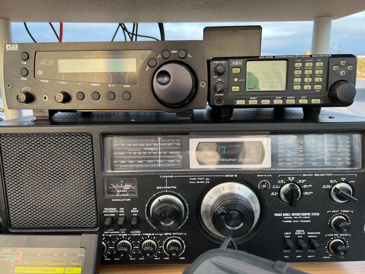
- AOR AR-ONE, another DC to 3 GHz general coverage radio, less well known due to the high price and limited US availability. Excellent performer, but a counterintuitive and awkward (menu-driven) user interface is less than ideal for shortwave, in my opinion.
- Reuter RDR Pocket, a very cute, if virtually impossible to get in the US, small production, high performance SDR-based shortwave portable receiver. It’s got an excellent spectrum display and packs near desktop performance into a surprisingly small package.
- AOR 7030Plus, an extremely well regarded mobile/desktop HF receiver from the late 90’s. Digital but retaining some important analog-era features like mechanical filters. Designed and (mostly) built in the UK, it’s got a quirky menu-driven user interface but is a lot of fun once you get used to it.
- Drake R8B, the last of the much-beloved Drake receivers. Probably the chief competitor to the 7030+.
- Drake R7A, an excellent analog communications receiver (but with a digital VFO) from the early 80’s. It still outperforms even many current radios.
- Sony ICF-6800W, a top of the line “boom box”-style consumer receiver from the early 80’s. Great radio, but hard to use on SSB, as we saw in Round One.
- Panasonic RF-4900, the main competition for the Sony. Boat-anchor form factor, but (improbably) can run on internal D-cell batteries. Generally impressive performer on AM, but, like the Sony 6800, difficult to tune on SSB.
 You may remember the above radios from Round One back in April. The new radios this time were:
- Tecsun 501x, a larger-format LW/MW/HF/FM portable released last year. As noted below, it’s a generally good performer, but regrettably susceptible to intermod when connected to a wideband external antenna (as we’ll see in Part One).
- Tecsun PL-990x, a small-format portable (updating the PL880), with many of the same features as the 501x. Like the H501x, good performance as a stand-alone radio, but disappointing susceptibility to intermod when fed with an external antenna.
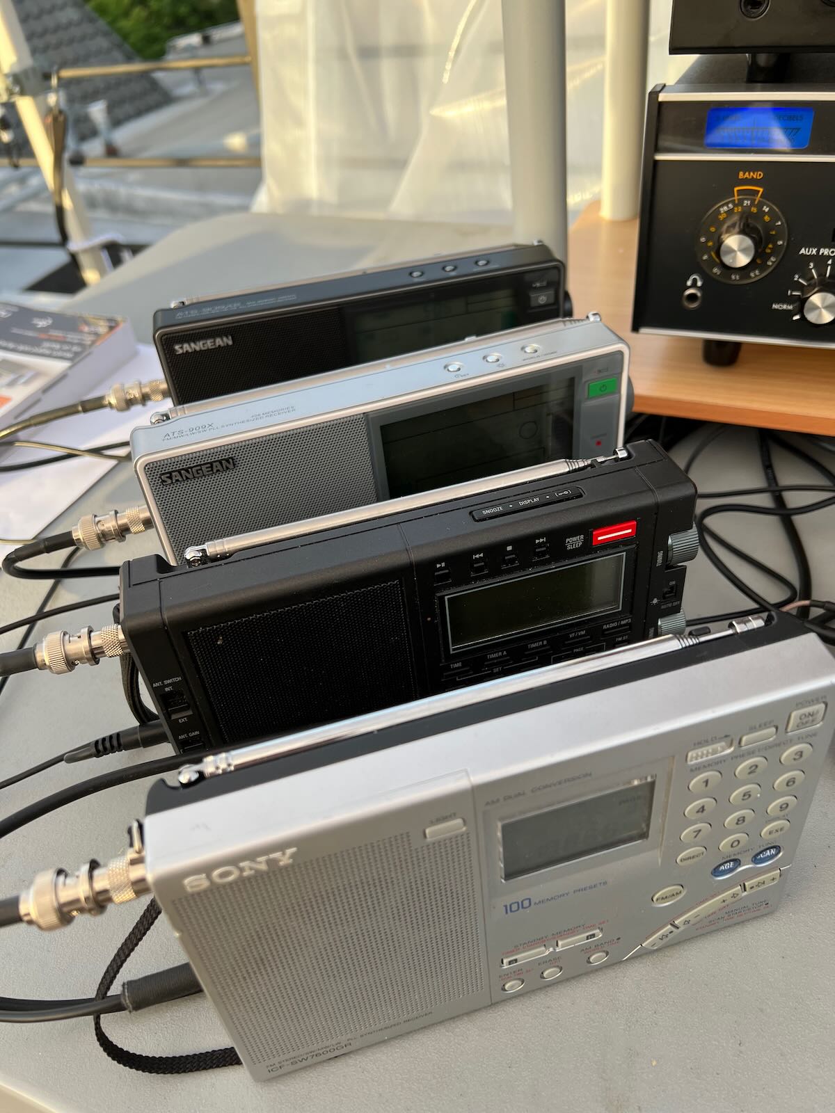
- Sangean ATS-909x, a recent LW/MW/HF/FM portable with a good reputation as well as a few quirks, such as only relatively narrow IF bandwidth choices on HF. Excellent performance on an external antenna.
- Sangean ATS-909×2, an updated, current production version of the ATS-909x that adds air band and a few performance improvements. Overall excellent, though I would prefer an addition wider IF bandwidth choice. My go-to travel receiver if I don’t want to take the Reuter Pocket.
- Sony ICF-7600GR, a small-format digital LW/MW/SW/FM portable introduced in 2001 and the last of the Sony shortwave receivers. Showing its age, but still competitive in performance.
- Belka DX, the smallest radio in our lineup, made in Belarus. You’ll either love or hate the minimalist interface (one knob and four buttons). If you’re going to secretly copy numbers stations in your covert spy lair, this is a good radio to use. Can be difficult to obtain right now due to sanctions.
- Finally, a bit of a ringer: the Narda Signal Shark 3310, a high performance SDR-based 8.5 GHz RF spectrum and signal analyzer. As with most test equipment like this, demodulation (especially of HF modes) is a bit of an afterthought. But it has an excellent front end and dynamic range, intended for identifying, extracting, and analyzing weak signals even in the presence of strong interference. Not cheap, but it’s intended as measurement-grade lab equipment, not consumer gear. Demodulated audio is noticeably delayed (several hundred ms) compared with other receivers due to the multi-stage DSP signal path.
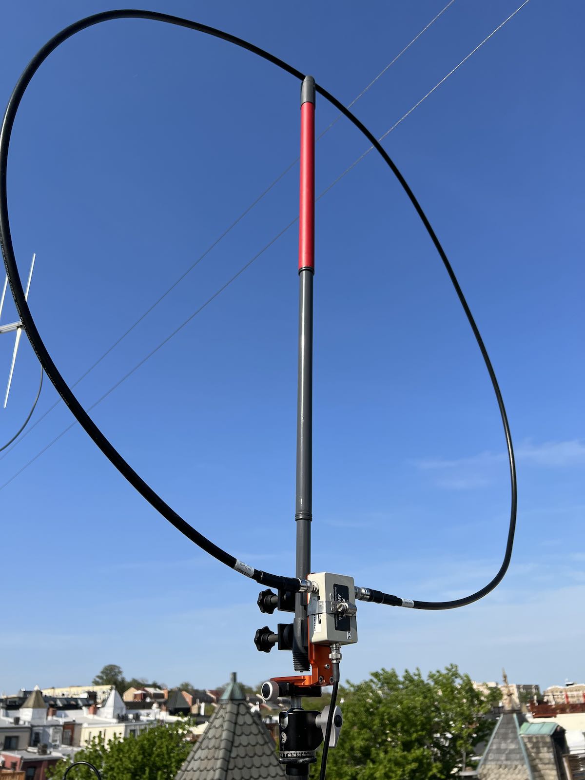
The antenna was my portable “signal sweeper” Wellbrook FLX-1530 on a rotatable tripod, using a power splitter and a pair of Stridsberg Engineering 8-port HF distribution amplifiers to feed the fifteen radios. So every radio was getting pretty close to exactly the same signal at its RF input. Continue reading