 Many thanks to SWLing Post contributor, Patrizio Cardelli, who writes:
I’m Patrizio (SWL I – 5184 /AN) from Riva del Garda, Italy.
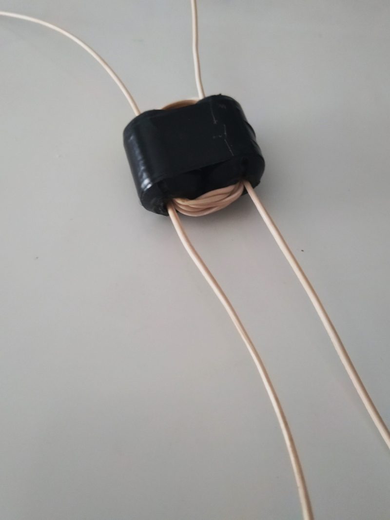
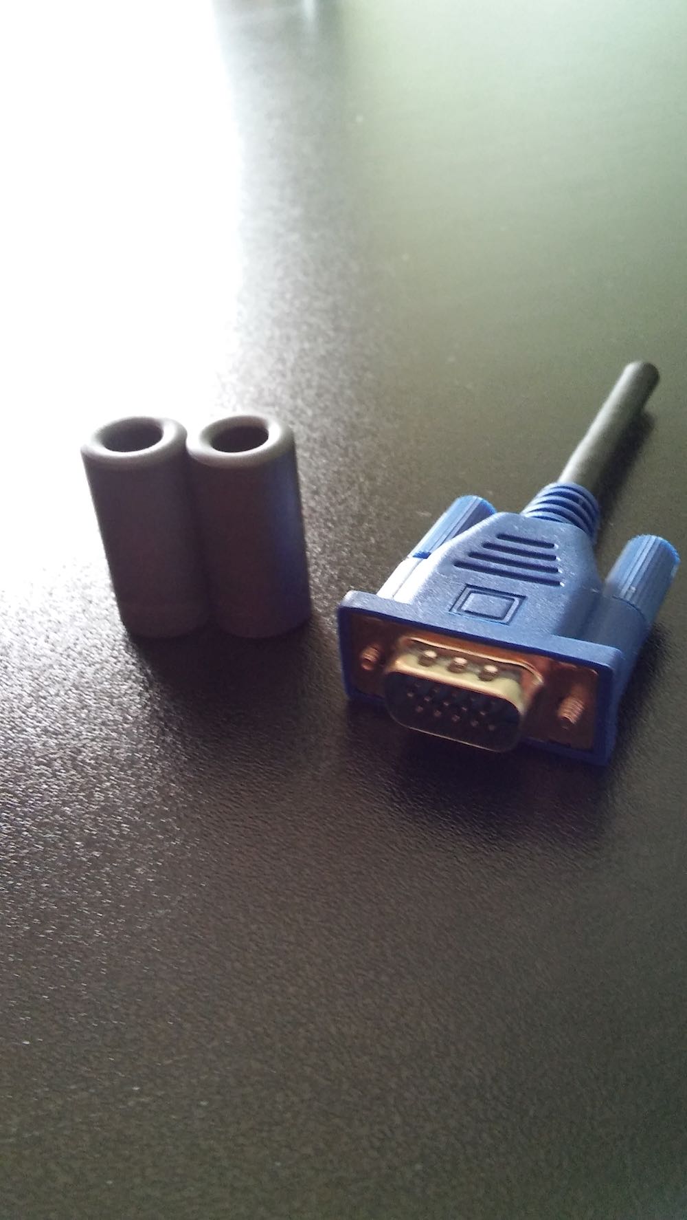
A few days ago, I built a Noise-Cancelling Passive Loop (NCPL) antenna. I built the 1:1 balun with a couple of ferrite 175 – 285.
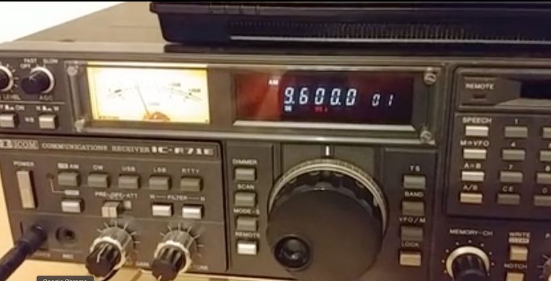
I got a good result on medium wave on my ICOM IC R 71 E with the antenna inside my house installed behind the desk just to avoid any problems with my wife.
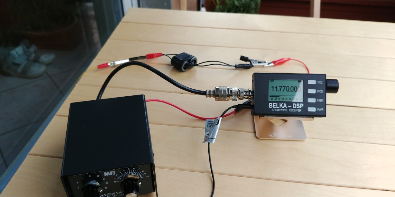
On shortwave, the signal was low in comparison with the Bonito mini whip but in my QTH I have a lot of QRM and with this antenna I solved my problem.
Yesterday I tried the balun with my random wire (15,2 meter long) also with good results.
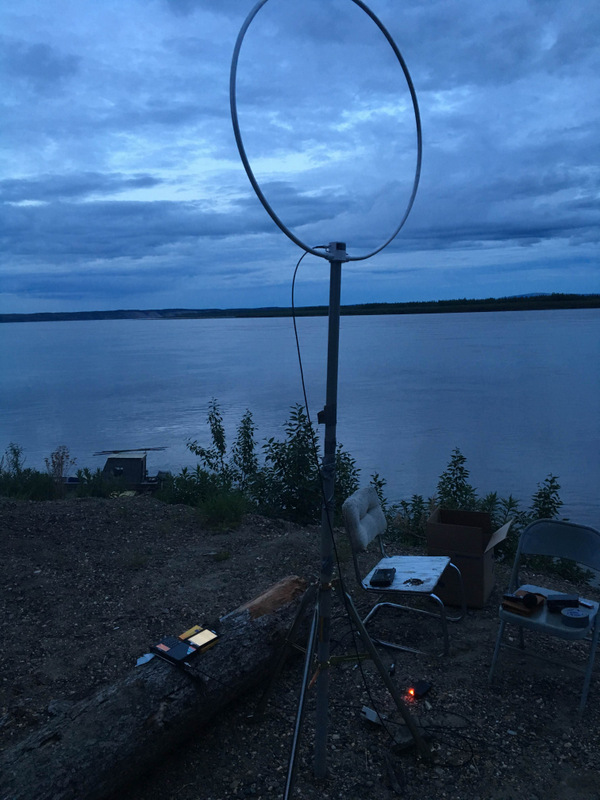
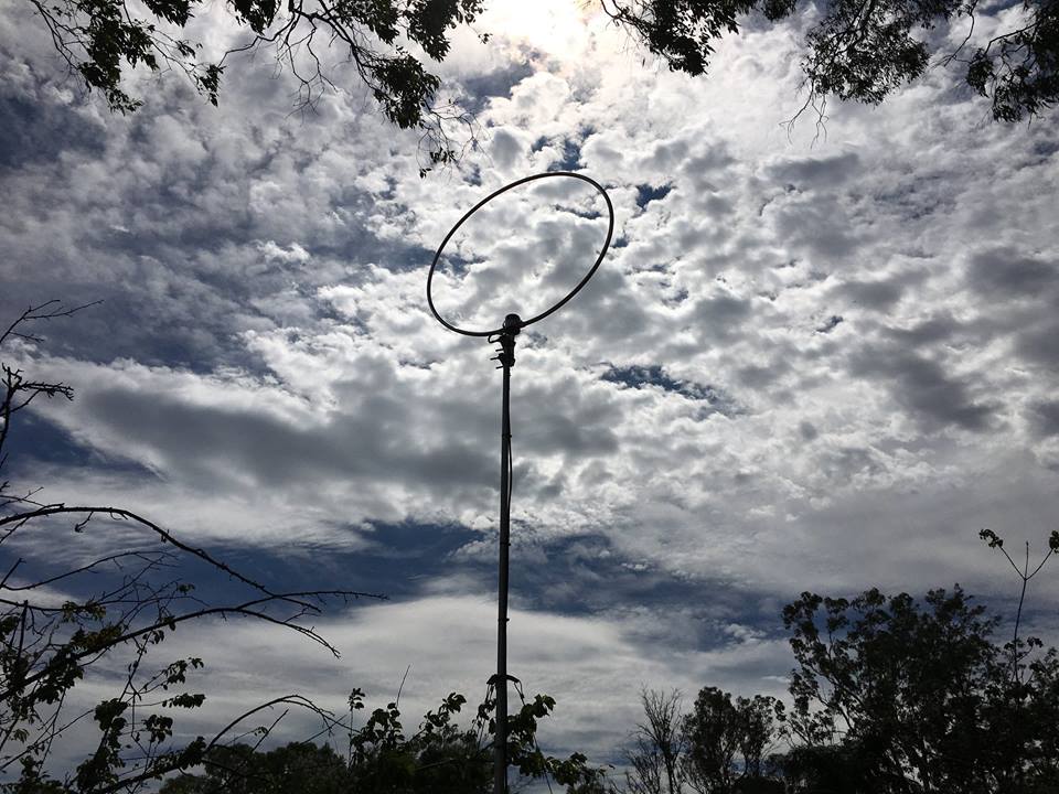
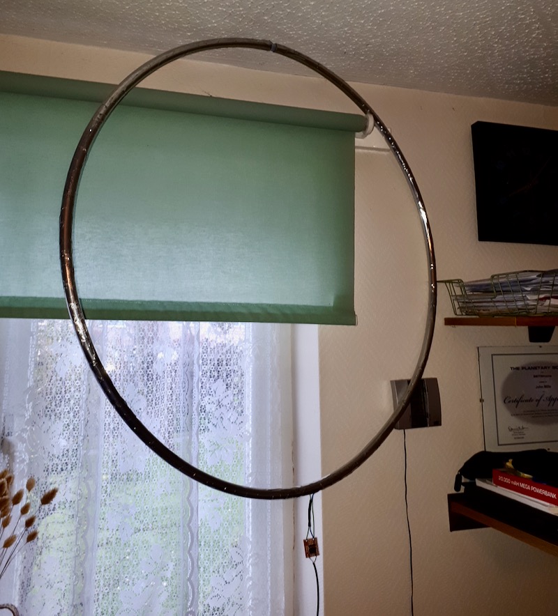
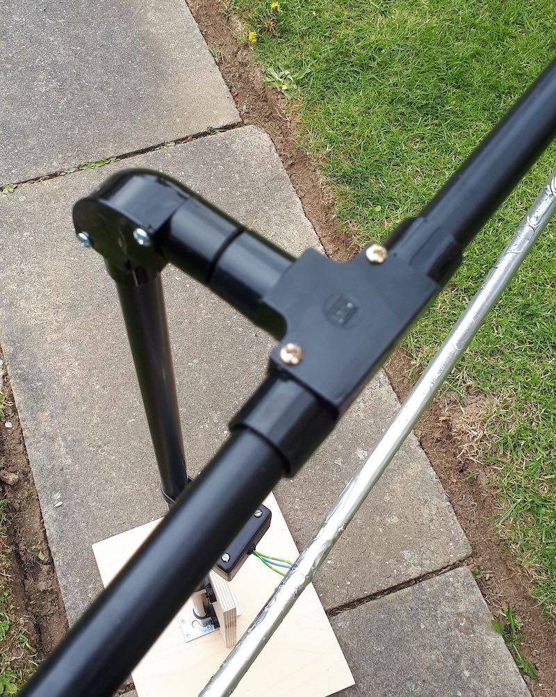
About my NCPL antenna: I made mine with RG-58 coaxial cable just to have easy portability in SOTA (please see photo) and also the feed line is made by the same coaxial cable. OK, you are right…it’s ugly:
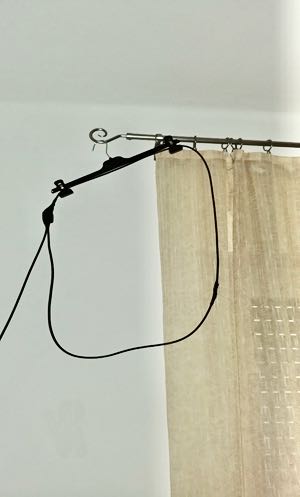
Electrical connections are not soldered, still I don’t see any mechanical issues and this antenna since it is made for SWL / BCL purposes (meaning, RX only, no TX).
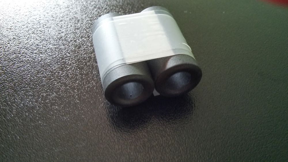
Concerning the binocular ferrite core, I didn’t have one, so I used two ferrite core type 175 – 285 (28,5 mm length, external diameter 17,5 mm and internal diameter 9,5 mm) normally used to reduce HF interference:
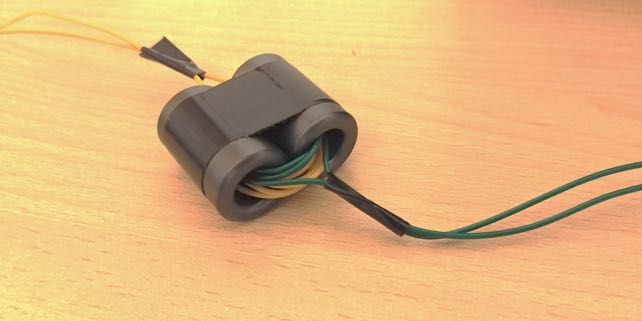
For the winding I used PVC insulated cable cat no: 7/0,2 type 2 (def61 – 12) conductor 7/0,2mm TSCu X 0,3mm R/T type single (4 turns primary and 4 turns secondary). It’s the same cable with which I built my random wire antenna (also portable for SOTA but now installed on my balcony until the COVID – 19 emergency is over).
The attached videos show the situation in comparison with my BONITO MINI WHIP active antenna (also installed inside my house). Recently I changed my QTH and unfortunately here I have a lot of interference both on MW and SW. The better results that you can hear are achieved with my NCPL antenna.
I have made this test with my ICOM IC R 71 E + BHI noise cancellation speaker…..you can assess yourself, the better results that you can hear are achieved with the NCPL antenna and in the case of Tecsun PL-660 without any noise cancelling filter (BHI speaker off).
Thanks for sharing this, Patrizio! As you say, the NCPL loop seems to do a fine job helping to eliminate local RFI/QRM. The Bonito Mini Whip is a fine antenna, but not optimal for environments with a lot of radio noise–that’s where the NCPL antenna really shines.
You also make a good point that if you’re simply experimenting and only using an antenna for receiving, you can be more relaxed about the build because you’re not sending RF through it. In the end, however, properly soldered and protected connections will last much longer and provide better, more reliable performance.
Thank you, again, for sharing your build, Patriio! Those reception results speak for themselves!