Tag Archives: Vlado

Vlado restores Mike’s vintage Sony CRF-160

Sony CRF-160 Dial

Many thanks to SWLing Post contributor, Michael Schuster, who shares the following guest post:


Vlado works his magic on my Sony CRF-160

by Michael Schuster

Back in the 1970’s my grandfather gifted this solid-state portable to me as it was more than he needed. It was the first “real” radio I can remember owning, and it initiated my habit of scanning the dials into the wee hours of the morning. I began my serious SWLing using this set as it had excellent sensitivity, dual conversion design, big booming audio, and generous bandspread tuning for each major SW broadcast band.

One of the best-known SWL programs at the time was Happy Station on Radio Nederland, and I have distinct memories of listening in our back yard one summer afternoon when the show came up on the African Service over the Madagascar relay. My family was astonished at the program coming from so far away and even more so when Tom Meijer happened to read my letter over the air during the mailbag segment!

Fast forward many years (and two moves) later, it sat on a shelf until, trying it out again, I was dismayed to find both slide rule tuning dials, and the rotary drum band selector, to be frozen in place. And so there it sat until….

In a few online forums I kept hearing about a magician named Vlado at Ham Radio Repair. He specializes in restoring old sets, and has the courage and curiosity to tackle just about anything. Thinking this might be my last chance to bring this fossil back to life, and armed with a scanned copy of the service manual downloaded from the Radio Museum web site (the Internet is a marvelous thing) I began a several months’ long email exchange with Vlado entitled “Would you be willing to work on…”

He is chronically swamped with sets to work on, and has little room to store pending jobs, but was more than willing to have a look. Several months, and one pandemic later, we touched base again and I arranged to ship this monster off to him. Vlado is especially interested in the stories behind old hardware, so I shared its history with him as it adds that extra “human factor”.

The radio is in great shape as he noted, but needed a total rework of the tuning dials and drum selector. He also replaced all of the electrolytic capacitors (most were leaking as pictured), replaced some tiny light bulbs with LED’s, and realigned all of the circuits for maximum performance.

Unpacking and trying out the restored set was a true blast and somewhat miraculous. It performs just as I remember and now sits on the shelf, this time in use rather than in storage, booming its audio across my basement work room.

Now this set will probably outlive me as it did my grandfather; hopefully it will end up in the hands of an appreciative recipient for the next generation of radio enthusiasts.


Thank you for sharing this repair story, Mike. I visited Vlado’s home a few weeks ago and saw the box labeled “Sony CRF-160” in-line to be repaired. As Vlado worked on it, he sent me a couple of photos, too, because I believe it was the first time he had ever worked on this particular Sony model. It is certainly a gorgeous radio–wow! And I do love your philosophy as it’s the one I adopt too: keep vintage radios alive and working beyond our generation. 

Vlado is truly the most capable ham radio repair guy technician/engineer you’ll ever meet. He’s also as honest as the day is long. If you have a vintage or late-model solid-state radio that needs repair or restoration, contact him.

Click here to check out Vlado’s website HamRadio.repair.

Spread the radio love

DIY: How to build a Noise-Cancelling Passive Loop (NCPL) antenna

I’ve gotten an number of inquiries from SWLing Post readers asking for a step-by-step guide to building the passive loop antenna I’ve mentioned in a number of previous posts. This antenna is the homebrew version of the commercially-available  Airspy Youloop.

It works a treat. And, yes, folks…it’s fun to build.

There are a number of loop designs out there, and to distinguish this one, I’m going to henceforth refer to this loop as in the title above:  the Noise-Cancelling Passive Loop (NCPL) antenna.

Before we start building, a little antenna theory…

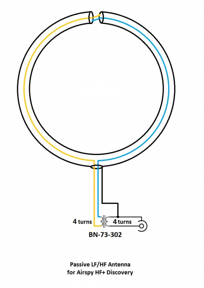
I’m neither an engineer nor am I an antenna expert, so I actually turned to Airspy president and engineer, Youssef Touil, to learn how, exactly, this passive loop works. Youssef was the guy who experimented with several loop designs and ultimately inspired me to build this loop to pair with his HF+ Discovery SDR and the SDRplay RSPdx. “The main characteristic of this loop,” Youssef notes,  “is its ability to cancel the electric noise much better than simpler loop designs.” Got that!  [See loop diagram below]

“The second characteristic of this loop antenna is that it is a high impedance loop, which might appear counterintuitive. This means it can work directly with many receivers that have a low noise figure, in order to mitigate the impedance mismatch loss.

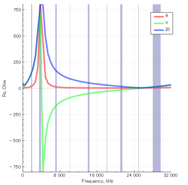
Note the resonance lobe near 4MHz. The resonance frequency is controlled by the diameter of the loop, the parasitic capacitance of the cable, and the loading from the transformer. It happens to be located right where we need it the most.

The transformer is basically a 1:1 BALUN that covers the entire HF band with minimal loss. Our BALUN has typically 0.28 dB loss.

[…]By connecting the center of this outer shield to the ground of the transmission line, you effectively cancel all the electric noise. The BALUN is required for balancing the electric noise, not for adapting the impedance.

[…]If you want to boost the performance in VLF, LW and MW, you can try a different impedance ratio, but this will kill the higher bands.”

What makes this loop so appealing (to me) is that it can be built with very few and common parts–indeed, many of us have all of the items in our junk boxes already. As the name implies, it is a passive design, so it requires no power source which is incredibly handy when you’re operating portable.

When paired with a high-dynamic range SDR like the Airspy HF+ Discovery or SDRplay RSPdx, you’ll be pleased with the wide bandwidth of this antenna and noise-cancelling properties.

If you don’t care to build this antenna, Airspy sells their own version of this loop for a modest $35 USD.

But building an antenna is fun and you can tweak the design to customize performance, so let’s get started:

Parts list

  • A length* of coaxial cable for the loop (see notes below regarding length)
  • Another length of cable terminated on one end with a connector of your choice as a feed line
  • A BN-73-302 Wideband 2-hole Ferrite Core
  • Enough coated magnet wire for a total of eight turns on the BN-73-302
  • Heat-shrink tubing or some other means to enclose and secure the cable cross-over point and balun. (You may be able to enclose these connection points with PVC or small electrical box enclosures, for example)
  • Electrical tape

Tools

  • A cable stripper, knife, and/or box-cutter
  • Soldering iron and solder
  • A heat gun (if using heat shrink)
  • Some patience 

*A note about loop cable length: Vlado and I made a loop with 1.5 meters of cable. The Airspy Youloop ships with two 1 meter legs that combine to give you an overall loop diameter of about 63.6 cm.

Step-by-step guide

When I first decided to build this loop, it was only a day prior to a trip to the South Carolina coast where I planned to do a little DXing. I didn’t have all of the components, so I popped by to see my buddy Valdo (N3CZ). Vlado, fortunately, had all of the components and was eager to help build this loop. As I’ve mentioned in previous posts, Vlado is an amazing engineer and repair technician, so when I say “we” built it, what I really mean is, Vlado did!  But I could’ve done it myself.

This is actually a very simple build––something even a beginner can do, as long as they’re okay with using a soldering iron. It does take patience preparing the loop cable properly. Take your time as you start, and you’ll be on the air in an hour or two.

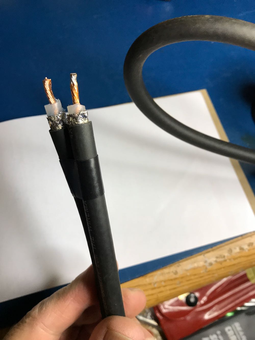
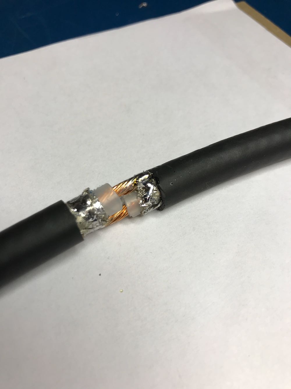
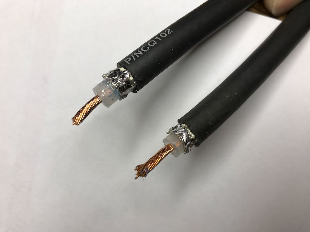
1. Strip the ends of the loop cable.

Although your cable type and diameter may vary, strip back the cable ends roughly like this.
To make finding the middle of the cable easier, we taped off the ends.

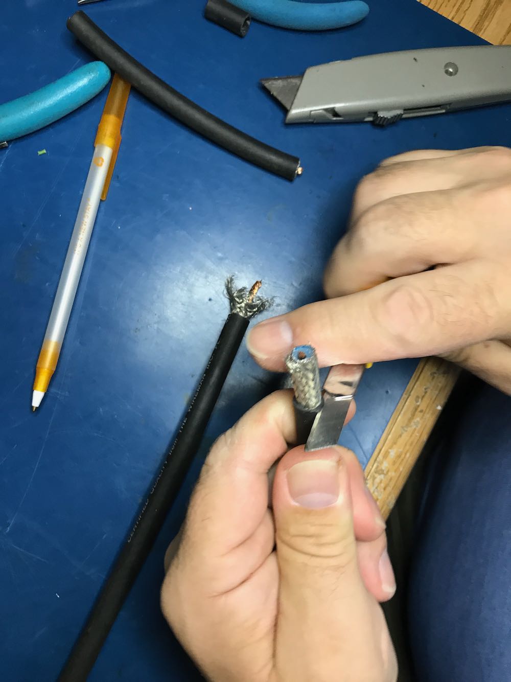
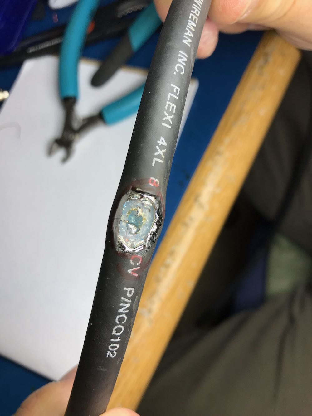
2. Make an opening in the middle of the cable to attach Balun leads to center conductor.

This is the trickiest part of the whole operation. The goal is to create an opening to tap into the center conductor of the cable.

You need to open a hole in the middle of the cable by

1 cutting away a portion of the outer jacket;

2 carefully separating and opening the shielding;

3 digging through the dielectric core, and finally

4 exposing the center conductor of the cable

Try to make an opening just large enough to gain access to the cable’s center conductor, but no bigger. Don’t allow any piece of the shielding to touch the center conductor.

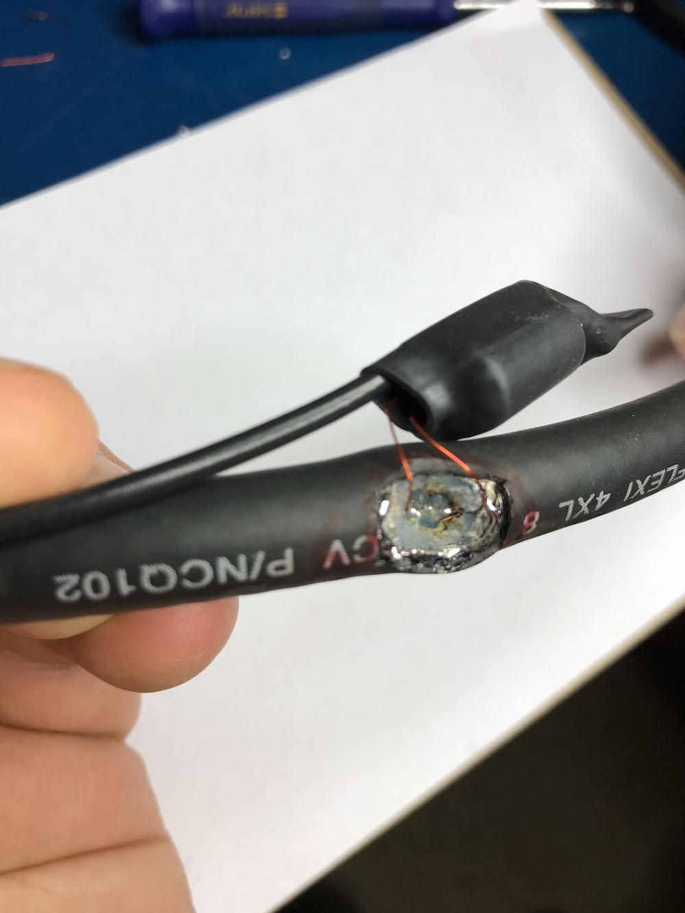
When you reach the center conductor, expose enough of it so that you can clip it in the middle and create an opening to solder your balun leads to both conductor ends.

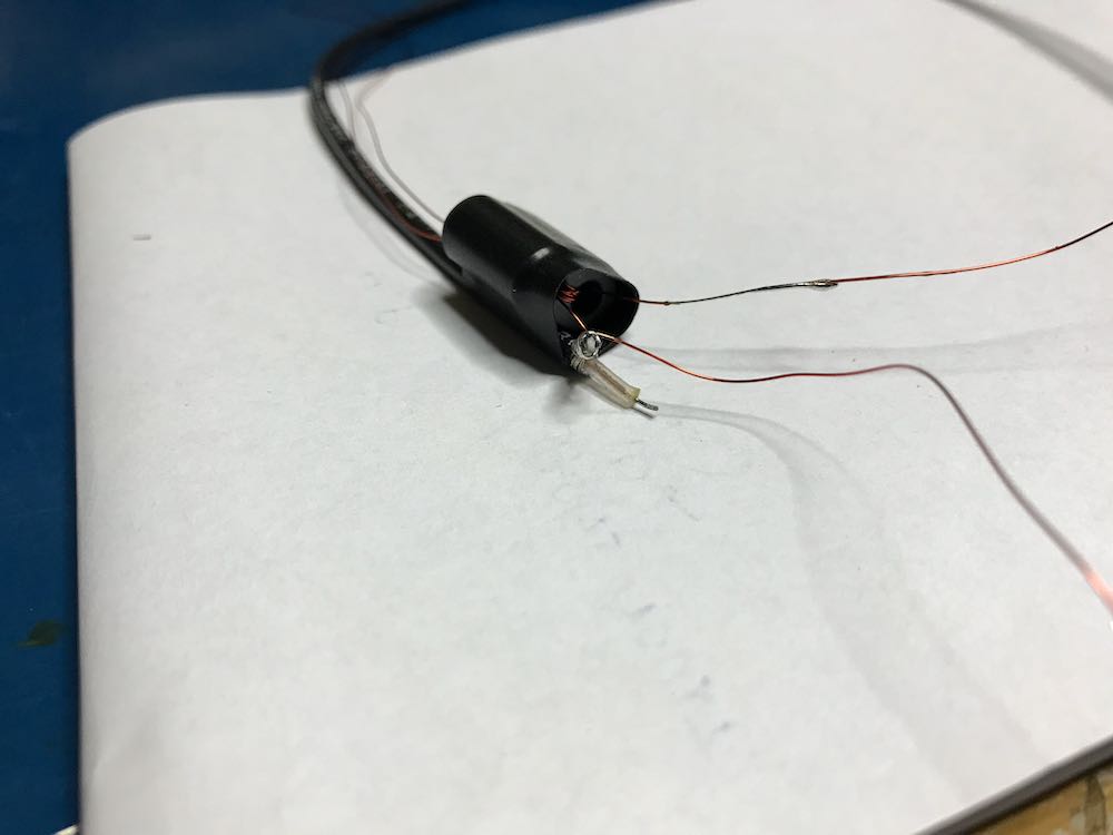
Once you’ve finished with this step, your cable should look something like this…

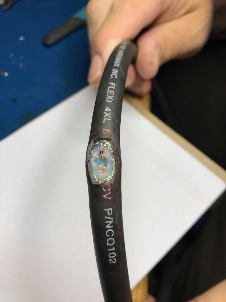
In the photo above, note that the shielding is completely pulled away, the dielectric core has been cut through, and we’ve clipped the center conductor, leaving a gap large enough to solder.
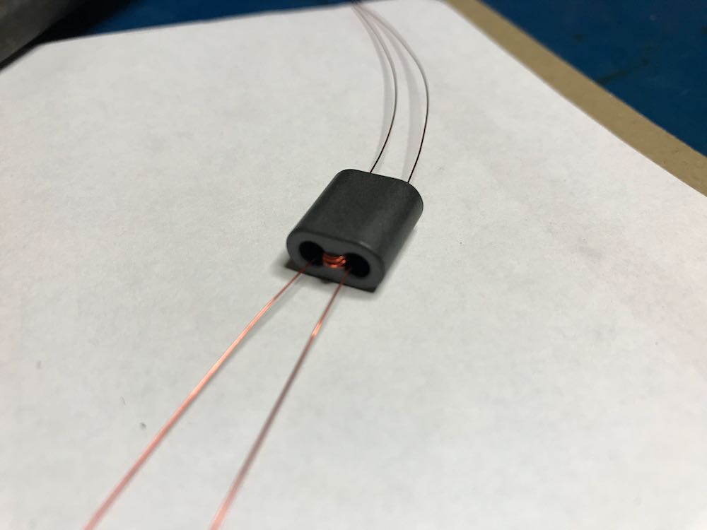
3.  Make a 1:1 Balun

Grab your BN-73-302, and with the coated magnet wire, make four windings on one side, and four on the other. It should look like this:

Don’t have a binocular ferrite core like the one above? If you have a broken cable with ferrite cores, you can hack one! Click here to learn more.

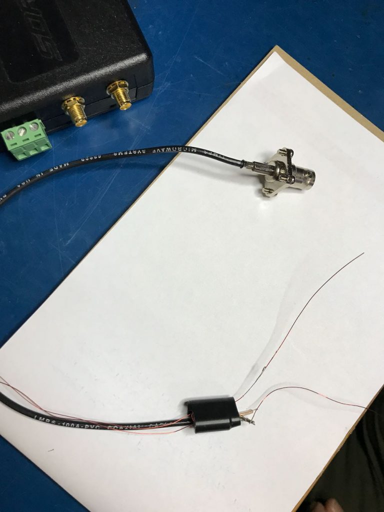
4. Connect the Balun to a feed line.

Vlado just happened to have a BNC pigtail in his shack (he’s that kind of guy), so we cut and stripped one end, then connected the center conductor and shield to one side of the balun. We then enclosed the balun in heat shrink tubing to make it a little easier to attach to the loop later:

Of course, you could also create this junction in a small enclosure box or short cross-section of PVC. There are a number of ways you could secure this.

Youssef also added the following note about the feedline:

To use the NCPL antenna without a preamp, it is recommended to keep the length of the cable below 10 meters. The supplied Youloop 2 meter cable [for example] is sufficient to keep the antenna away from the magnetic interference of a computer or a tablet, and has very low loss and parasitic capacitance.

5. Connect Balun to the coaxial loop.

To make a solid connection, tin both sides of the center conductor. Next, attach the other end of the balun leads to each portion of the center conductor, as seen below:

Update: Note in the loop diagram near the top of the page that the ground wire on the output connector connects to the loop coax shielding on the primary side of the balun. I don’t recall that we did this in the build, but I would encourage you to do so. This should result in even lower noise, although admittedly, I’m very impressed with the performance of ours without this connection. Thanks to those of you who pointed out this discrepancy!

6. Secure the Balun/Coax junction.

Since this loop is intended to be handled quite a lot in the field, make sure the junction point of the balun and coax loop is secure. Again, we used several layers of heat shrink tubing since we had some in the shack.

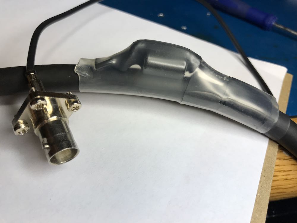
7. Solder and secure the cross-over point.

Next, create the cross-over point of the loop by simply attaching the center conductor of one end of the cable to the shielding on the other end…and vice versa.

Before you grab the soldering iron, howeverif, like we did, you’re using heat shrink tubing to secure the cross-over point of the loop in the next step, you’ll first need to slide a length of tubing onto the coax before you solder the ends together. Vlado, of course, thought of this in advance…I’m not so certain I would have!

Take your time soldering this connection and making it as solid as you can. If you solder it correctly, and you’re using a high-quality cable as we did, the cross-over point will be surprisingly durable. If you’re using a thinner cable, simply make sure the connection is solid, then use something to make the junction less prone to breaking––for example, consider sealing a length of semi-rigid tubing around this point.

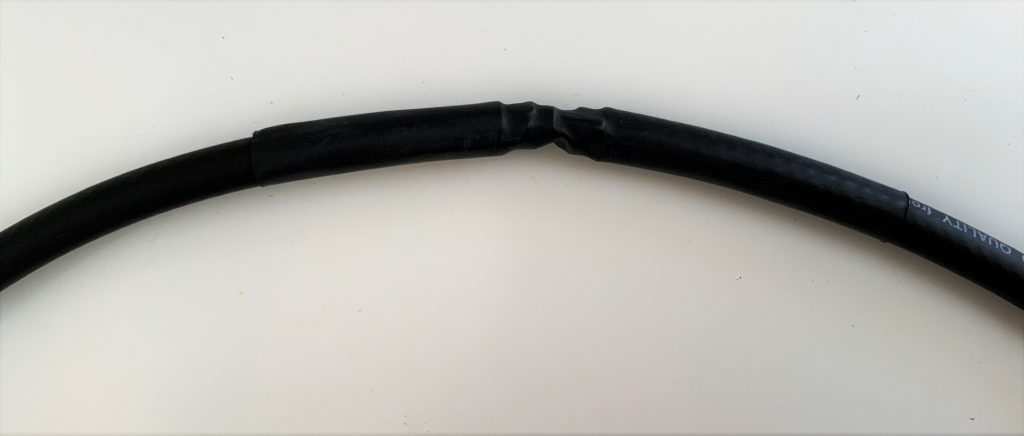
Vlado cleverly added heat shrink tubing around the cross-over point to protect and secure it.
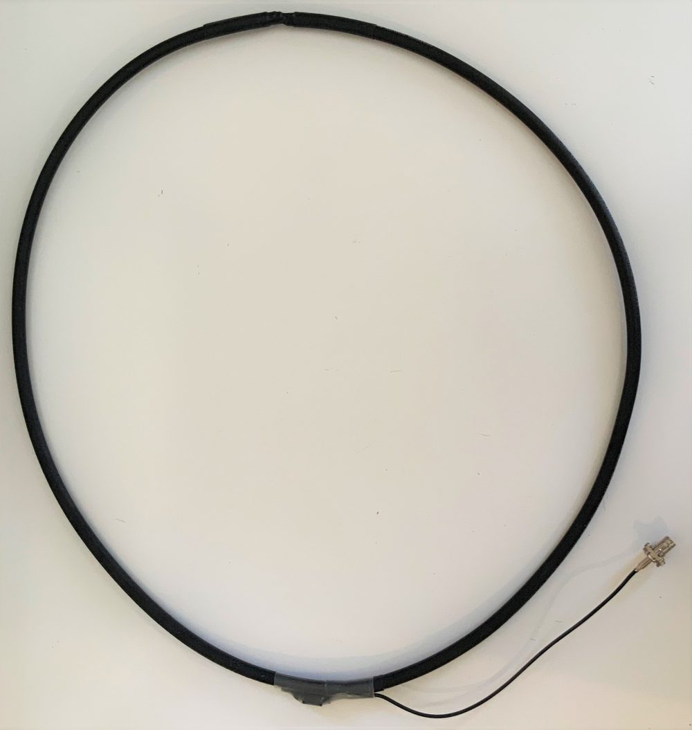
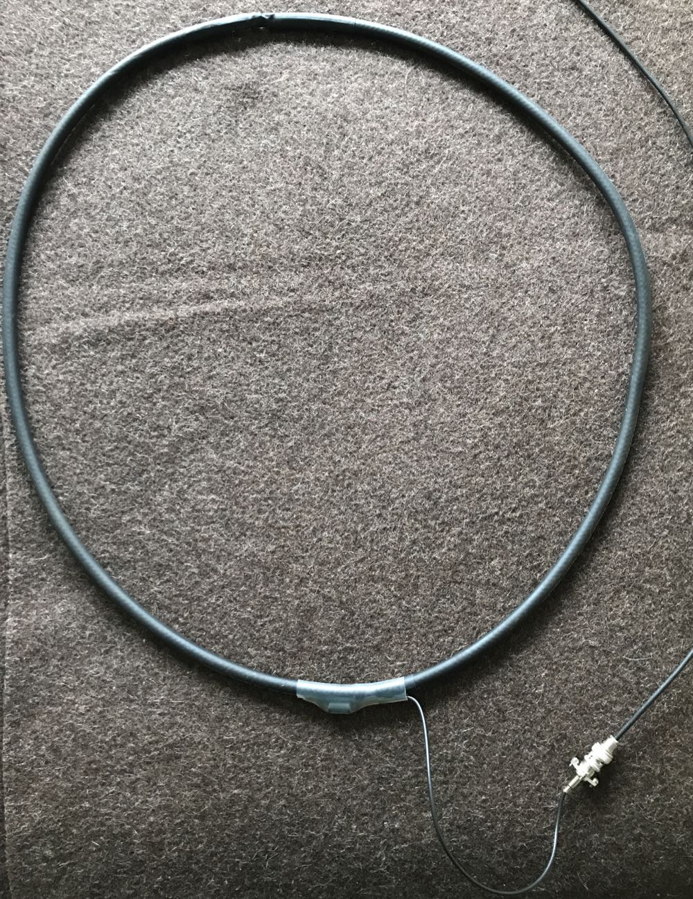
You’re done!

That’s all, folks! Now you’re ready to put your loop on the air.

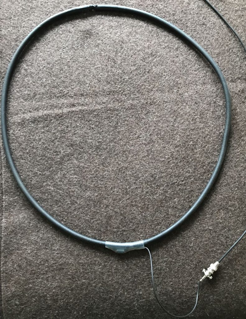
Depending on what type of cable you used for this loop, you might require or prefer some sort of dielectric structure to support the loop so that it maintains the ideal round shape. My loop maintains its integrity pretty well without supports. I’ve supported it a number of times with fishing line/filament from two sides (tying on at 10 and 2 o’clock on the loop). That seems to work rather well.

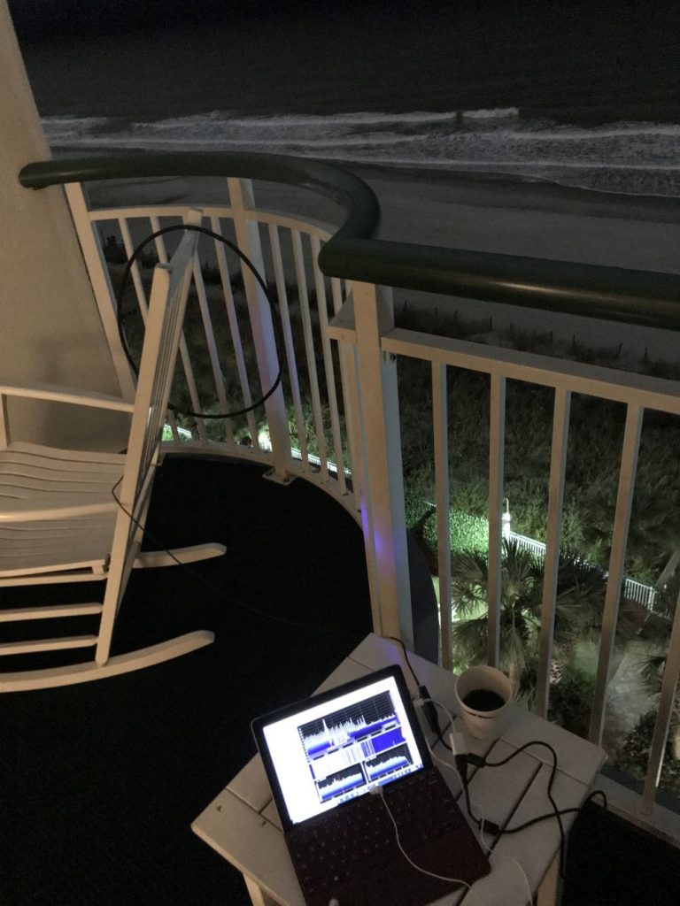
In this setup, I simply used the back of a rocking chair to hold the antenna. As you can see, the loop maintained its shape rather well.

If you’d like to see and hear how this antenna performed on its first outing, check out this post.

Show the Post your loop!

If you build a NCPL antenna, please consider sharing your design here on the SWLing Post! Considering that there are a number of ways this loop can be built, and likely even more optimizations to improve it or make its construction even easier, we’d love to see your designs and/or construction methods. Please comment or, if you prefer, contact me.

And many thanks to my good friend Vlado (N3CZ)  for helping me with this project and allowing me to document the process to share it here on the Post. Got a radio in need? Vlado’s the doctor!


Enjoying the SWLing Post?

Please consider supporting us via Patreon or our Coffee Fund!

Your support makes articles like this one possible. Thank you!

Spread the radio love

Doctor Vlado repairs the Panasonic RF-2200 (Part 1)

Panasonic RF-2200 at Hamvention

Last year, at Hamvention, I picked up a Panasonic RF-2200 for $70. It came with the original box, manual and was in superb cosmetic condition.

The seller told me that over the years he exclusively used the radio to listen to a local FM station.

At that price, I didn’t hesitate to make the purchase even if this would have simply been a non-functioning parts radio for my other RF-2200.

After I brought the radio home, I unpacked it and gave it a quick test.

FM worked brilliantly. Mediumwave and shortwave, however, were essentially deaf. I made the assumption that the ‘2200’s switches and pots likely needed cleaning with DeoxIT. The next day, I was leaving for a two month trip to Canada though, so I packed the RF-2200 back into its box and set it to the side of my shack table.

Fast-forward to yesterday…

While digging around my shack, I re-discovered the boxed RF-2200. Since I was planning to visit my buddy Vlado (the best radio repair guy in the world) yesterday evening, I thought I’d take the RF-2200 and do a proper contact cleaning. Several of the RF-2200’s switches and pots cannot be easily cleaned without removing the chassis.

(Click photos to enlarge.)

Vlado is familiar with the RF-2200 and since it’s not the easiest radio to work on, I asked for his expert hands on the job. Within seconds of handing him the radio, he plugged it in, tested the switches and pots, then removed the back cover (disconnecting the battery compartment leads) and then the front cover (disconnecting the speaker leads).

The magic behind the RF-2200’s classic analog dial:
Vlado offered a word of caution to anyone operating on their RF-2200: as you can see in the photo below, the dial string snakes around the front of the radio and is very close to some key components. You must exercise caution when having a soldering iron tip near the string, or using lubricants nearby.I didn’t realize this, but by the time Vlado started taking apart the RF-2200, he had already determined that even though the contacts needed cleaning, this wasn’t the source of the audio problem for the MW and SW bands.Vlado expertly pulled out the pot for the FM/AM/SW selection–not an easy task–began cleaning it, testing it and re-soldering contacts.

Vlado determined the pot was actually in good shape, thus started testing the rest of the circuit.

After a few minutes of performing tests and getting intermittent performance, he determined that at least one, if not more, of the RF-2200’s caps need to be replaced. Of course, neither one of us was terribly surprised. At this point though, it was getting late and I had an early wake up time in the morning, so I left my RF-2200 with Vlado.

Am I worried about this prognosis?  No, not in the slightest…

Doctor Vlado is on the job!

Vlado will have the RF-2200 back on the air in no time, working as well as it did when it was new. He’s actually performed a similar RF-2200 repair for an SWLing Post reader and I’m willing to bet this repair job is relatively simple compared to most he encounters (including the Icom IC-7200 he recently repaired after it was hit by lightening!).

I’ll try to post a “Part 2” update with photos of the RF-2200 repair.  Follow the tag: Panasonic RF-2200 Repair

Spread the radio love

A photo tour of the 2018 Greenwood, SC hamfest

Last week, my buddy Vlado (N3CZ) informed me about a small hamfest in Greenwood, SC–I had never attended, but had heard positive comments about it.

I believe Vlado was somewhat on the fence about going, but once I expressed a strong interest in selling some gear, he did too so it quickly became a plan!

Greenwood, South Carolina, is about a 2.5 hour one-way drive from my home. Vendors were encouraged to arrive around 7:00 to set up (general public admission was at 9:00), so Vlado and I hit the road by 4:30 AM!

Notice the lack of traffic on the interstate at 4:30 AM!

We arrived as the doors opened and purchased a total of three tables to sell our gear. My goods took up most of one table and Vlado packed the other two with his gear!

By general admission time, less than half of the vendor tables were occupied, which did worry me. However, overall foot traffic wasn’t bad at all! This vendor was certainly pleased.

I sold at least 80% of the items I brought with me, no doubt due to my generous and agressive pricing scheme (i.e. nearly giving things away–!). Vlado sold some large items, too.

In the end, I didn’t purchase a single item at the hamfest. I was in selling mode, not buying mode, at this hamfest as I’ve been making an effort to downsize some of my collection and use the money to offset the costs of travel this year. With that said, I would have snagged a classic portable had one appeared.

This BC-317 is just asking to be taken home!

Mind you, I was very tempted by two BC-317 receivers being sold together for an asking price of $60, but I resisted as the whole idea of “thinning the herd” is to make room in my small radio shack.

I find that small hamfests like Greenwood actually have better vintage radio pricing than the larger ‘fests.

Greenwood Photo Gallery

Though the hamfest was modest in size, there were quite a few quality offerings among the vendors. I was very impressed with the number of transceivers–indeed, a new ham would have had a selection of affordable benchmark 90s era rigs to choose from!

Click on the thumbnails below to enlarge or comment on the photos. Most of the photos were taken prior to the doors opening but I did my best to capture price tag information if available:

Do I plan to revisit Greenwood next year? You bet!

Spread the radio love

Video: Juan touts Panasonic RF-2200 performance & filter shapes

Many thanks to SWLing Post contributor, Juan Pablo Carlino, who writes:

Hi. I own one RF-2200 after buying it in eBay in March 2008. Since then it became my favourite portable radio and as everybody [has commented], its a pleasure to hear MW with it.

I explain this due to the fact that it has a good rotative ferrite antenna and also because the narrow and wide filters have a suitable shape for MW: at least in my country each MW is spaced from the other by 10 KHz, so you don’t need a very sharp filter. The narrow one is not so narrow, just enough to attenuate maybe 6 db the splatter from the louder station and not loosing audio quality.

When you tune around you have the impression that the filter shape suites perfectly for MW, making the audio quality very pleasant. I would never sell it. If you are interested i’ve captured a short clip while playing with it outdoor on 7 MHz band, hearing ham stations on AM, SSB and CW.

Pay attention to how loud and clear i was hearing stations at 400 Km in AM:

Click here to view on YouTube.

Many thanks for sharing your thoughts, Juan!

I agree with you completely. At least here in countries where MW stations are spaced at 10 kHz, I find the RF-2200 a mediumwave DX boss!

I’m constantly amazed with the RF-2200’s MW sensitivity and selectivity–and low noise floor. That combo, along with the filter shapes Juan mentions and the excellent built-in full-fidelity speaker make for a proper listening experience.

As I’ve said before, the RF-2200 is a radio with fortitude and purpose.

The only place I’ve ever really searched for an RF-2200 is eBay. I like eBay, because if you receive a faulty unit, you can typically return it or have some sort of recourse (as long as the seller accepts returns).

I would only buy an RF-2200 (or any vintage solid-state rigs) from a seller that has near 100% ratings with a number of radio sales in their past.  That is, if you’re seeking a working unit.

Though the RF-2200 is vintage and thus might eventually need repair. It’s ultimately reparable by a skilled technician, though.  My buddy Vlado, for example, has repaired 2200s in the past–indeed, we cracked my RF-2200 open a few months ago to clean contacts.

Panasonic RF-2200s typically cost between $175-300 for one that’s mechanically and cosmetically sound. Of course, NOS units go for much more and units with faults sell for much less.

I expect my RF-2200 will outlast me!

Click here to search for RF-2200s on eBay.

Spread the radio love

NPOTA activation on the Blue Ridge Parkway

A crowd gathers as Vlado (N3CZ) works station after station in CW!

A crowd gathers as Vlado (N3CZ) works station after station in CW!

I’m not sure what I’m going to do after the National Parks On The Air event is over at the end of this year. I hope the ARRL organizes something equally as fun for 2017.

Truth is, I love playing radio outdoors and I love National Parks. The two are a perfect combo.

Vlado (N3CZ) on left, and me (K4SWL) on right.

Vlado (N3CZ) on left, and me (K4SWL) on right.

My buddy, Vlado (N3CZ), and I decided to do an NPOTA activation on Sunday. The weather was fantastic–a little foggy with mild temperatures and the HF bands were open!

We arrived at our site–the Craggy Gardens Picnic Area (PK01)–at 14:30 UTC or so.

KX3-PK01-NPOTA

We brought the following antennas and supports:

  • a self-contained  20 meter band telescopic fiberglass vertical (I recently purchased at the WCARS Hamfest for $40–!) and
  • a 31 foot fiberglass Jackite pole (the fluorescent orange on in the photos) which we used to suspend a homemade 40 meter doublet Vlado built the day before.

Setup was quick. We were both especially pleased the 20 meter vertical. It was so easy to install, even considering it was the first time either of us had used it.

I powered the LD-11 and the KX3 with my QRP Ranger.

The 20 meter vertical antenna.

The 20 meter vertical antenna (in foreground).

I operated SSB from a picnic table using the LnR Precision LD-11 transceiver, connected to the doublet on 40 meters, and the mono-band vertical on 20 meters.

LD-11-QRP-Ranger-NPOTA-PK01

Vlado started by operating CW with his Icom IC-7000 which was installed in his car, but later moved to the picnic table and logged a number of contacts with the Elecraft KX3.

N3CZ--NPOTA-PK01

We easily logged the number of stations needed to activate the site.

The 40 meter band was hopping and a good path was open into Ohio, Virginia and other surrounding states. The 20 meter band was serving up some excellent QRP DX.

Vlado-KX3

Vlado operating CW on the 40 meter band.

When I moved to the 20 meter band, the noise floor was so low on the LD-11, I thought perhaps the band was dead.  Not so!

LD-11-NPOTA-PK01

It’s hard to believe that with a mere eight watts in SSB  I worked Rhode Island, Texas, Montana, Manitoba, Washington, California and Slovenia from a picnic table on the Blue Ridge Parkway.

Reports on the LD-11 audio were all very positive. I’ve used the LD-11 for eight NPOTA activations this year and can say with confidence that it’s a brilliant & fun little field radio. (FYI: I’ll be publishing a full review of the LD-11 in the October 2016 issue of The Spectrum Monitor magazine.)

Vlado and I are planning on several more activations together this year. Our next one will most likely be at the Carl Sandburg Home-. I can’t wait!

Any other post readers participating as an activator or chaser in the National Parks on the Air event?

Spread the radio love

National Parks On The Air: Activating PK01 this weekend (August 28)

The QRP Ranger (left) and LNR Precision LD-11 transceiver (right)

The QRP Ranger (left) and LNR Precision LD-11 transceiver (right)

After two months in Canada and one month spent catching up on work, I’m pleased to make some time this weekend to activate PK01 (the Blue Ridge Parkway) for the ARRL National Parks On The Air (NPOTA).

I’ll be joined by my good friend, Vlado (N3CZ) on August 28–we plan to set up at the Folk Art Center on the parkway around 11:00 EDT and be on the air by 11:30 EDT (15:30 UTC).

I plan to use the LNR Precision LD-11, QRP Ranger and EFT Trail Friendly Antenna combo. Vlado will either use his Icom IC-7000, Kenwood TS-480 or my Elecraft KX1.

Look for us on the following frequencies:

  • CW: +/- 7031, 14061 kHz
  • SSB: +/- 7286, 14286 kHz

Life has been so hectic after having been on the road for two months–I’m pleased to finally have a moment to play radio in the field again!

Spread the radio love