 Radio Waves: Stories Making Waves in the World of Radio
Because I keep my ear to the waves, as well as receive many tips from others who do the same, I find myself privy to radio-related stories that might interest SWLing Post readers. To that end: Welcome to the SWLing Post’sRadio Waves, a collection of links to interesting stories making waves in the world of radio. Enjoy!
Many thanks to SWLing Post contributors Kim Elliott and Dennis Dura for the following tips:
Scientists create quantum sensor that covers entire radio frequency spectrum (Phys.org)
A quantum sensor could give Soldiers a way to detect communication signals over the entire radio frequency spectrum, from 0 to 100 GHz, said researchers from the Army.
Such wide spectral coverage by a single antenna is impossible with a traditional receiver system, and would require multiple systems of individual antennas, amplifiers and other components.
In 2018, Army scientists were the first in the world to create a quantum receiver that uses highly excited, super-sensitive atoms—known as Rydberg atoms—to detect communications signals, said David Meyer, a scientist at the U.S. Army Combat Capabilities Development Command’s Army Research Laboratory. The researchers calculated the receiver’s channel capacity, or rate of data transmission, based on fundamental principles, and then achieved that performance experimentally in their lab—improving on other groups’ results by orders of magnitude, Meyer said.
“These new sensors can be very small and virtually undetectable, giving Soldiers a disruptive advantage,” Meyer said. “Rydberg-atom based sensors have only recently been considered for general electric field sensing applications, including as a communications receiver. While Rydberg atoms are known to be broadly sensitive, a quantitative description of the sensitivity over the entire operational range has never been done.”[…]
Forty years ago today Sheerness lifeboat crew rescued Radio Caroline DJs from the sinking Mi Amigo (Kent Online)
It was the original ‘ship that rocked.’ But 40 years ago today (Thursday)the Mi Amigo, home to original pop pirates Radio Caroline, finally disappeared beneath the waves in a violent force 10 storm.
In a daring rescue which lasted 12 hours in appalling weather, the crew of the Sheerness lifeboat saved the lives of everyone onboard – including the ship’s canary.
Leading the operation was colourful RNLI coxswain Charlie Bowry, who was later presented with the Institute’s coveted silver medal.
It was during the day that the radio station’s 60-year-old ship started dragging its anchor and drifted 10 nautical miles onto the Long Sand sandbank off Southend.
As the tide rose, the ship started to float free. But the bottom of the boat began being buffeted on the seabed with such a force the steel plates sprung a leak and water gushed into the engine room.
When the bilge pumps couldn’t cope, the three British DJs and a Dutch engineer called the Coastguard who dispatched Sheerness lifeboat the Helen Turnbull.[…]
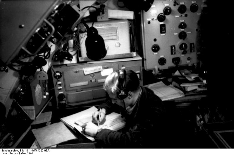
The Radio Network that Allowed Communication with Submarines (Interesting Engineering)
Communicating with covert fleets during WWII required some special equipment.
What do you do when you need to communicate with a crew of 50 sailors submerged in a submarine in an undisclosed location across the world’s oceans? That was a difficult question to answer for Navy leaders in WWII.
Radio waves don’t easily travel through saltwater, which meant that getting active communication with a submarine crew meant making the submarine surface an antenna. This was the obvious solution, but it made a previously covert submarine now a visible target.
[…]Engineers tasked with finding a more covert solution soon discovered that radio waves with low frequencies, around 10 kHz, could penetrate saltwater to depths up to around 20 meters. They realized that if the transponders on submarines were switched to these frequency ranges, then they communicate with leadership on land.
The problem with this idea was that creating and broadcasting these low-frequency radio waves required massive antennas. Essentially, the lower the frequency of a radio wave, the longer and larger the antenna is required to be.[…]
You Could Download Video Games From the Radio in the 1980s (Interesting Engineering)
Certain radio programs broadcast the raw data to video games for viewers to download.
[…]In 1977, the world’s first microprocessor-driven PCs were released. These were the Apple II, the Commodore PET, and the TRS-80. All these machines had one thing in common – they used audio cassettes for storage.
Hard drives at the time were still quite expensive, and everyone at the time had access to cheap audio cassettes. Early computer designers actually flaunted cassette storage as it aided in the early adoption of personal computers. As PCs became more common, so to did the emergence of their use as video game machines.
As the 1980s rolled around, engineers at the Nederlandse Omroep Stichting, NOS, a Dutch broadcasting organization, realized something incredible. Since computer programs and video games were stored on audio cassettes, it meant that their data could be transmitted with ease over the radio. They started taking programs and video games and setting up broadcasts where people could “download” games onto their own personal computers.
The audio that was transmitted would’ve sounded reminiscent of a dial-up modem booting up.
[…]NOS started a radio program specifically for transmitting gaming data called “Hobbyscoop,” and it became incredibly popular. The company even created a standard cassette format called BASICODE to ensure computer compatibility.
Eventually, transmitting games through computers became so popular that radio shows popped up all around the world. A Yugoslovik station called “Ventilator 202” broadcasted 150 programs between 1983 and 1986. As the practice evolved, it became less of a novelty and rather a practical way for people to share calculation programs, educational tools, encyclopedias, and even flight simulators.[…]
Do you enjoy the SWLing Post?
Please consider supporting us via Patreon or our Coffee Fund!
Your support makes articles like this one possible. Thank you!