Category Archives: Ham Radio

Tony performs a quick LNA4ALL test

Many thanks to SWLing Post contributor, Tony Roper, who shares the following guest post which originally appeared on his blog, Planes and Stuff:


Quick LNA4ALL test

by Tony Roper

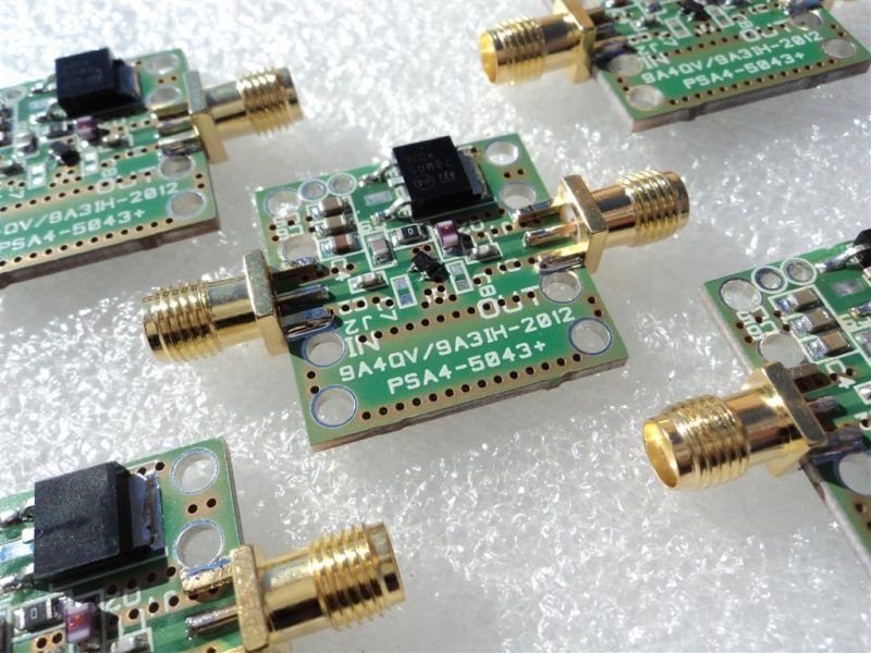
Despite the best efforts of the Royal Mail service, I have been able to get my hands on a Low Noise Amplifier created by Adam at LNA4ALL. The Royal Mail showed just how useless it is, when the parcel arrived here in the UK in just 11 hours from Croatia on February the 14th, but then not getting delivered to me until March the 14th – yes, one month! There is no surprise that courier companies such as DPD and Hermes are getting more business than the Royal Mail – they are bloody useless.

Anyway, the reason for the purchase is for a later review on an AIS dongle that I will be testing, but which has unfortunately been possibly damaged before getting to me.

So, as I had some time to spare I thought I’d run a quick test on how the LNA performs against the claims that is shown on the LNA4ALL website. For the test I used a quickly built 12v to 5v PSU that was connected to a Maplin bench PSU and also a Rigol DP711 Linear DC PSU where I could ensure a precise power input. As it was, it was good that I used the DP711 because my quick PSU was only chucking out 1.2v at connection to the LNA4ALL, despite an unconnected output of 5v – some work needed there I think.

Despite this lower power the LNA4ALL still worked with just the 1.2v input, though the results where not as good.

Other equipment used were a Rigol DSG815 Signal Generator and a Rigol DSA1030 Spectrum Analyser (no longer available), along with various Mini-Circuits shielded test cables. The Rigol equipment I purchased from Telonic Instruments Ltd last year.

Below then is a table that contains all the relevant data. As you’ll see the Gain claim is pretty much spot on with some being over. Just a couple of frequencies are below that which is claimed, especially at 28 MHz.

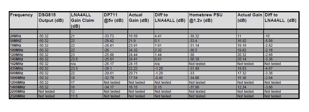
LNA4ALL Frequency data

A couple of things to note.

Firstly, somehow I managed to miss testing 1296 MHz. I obviously didn’t put it in the table in Excel before I started ? Also, the DSG815 only goes up to 1.5 GHz so I couldn’t test above that.

Secondly I ran a test for the AIS centre frequency of 162 MHz, for which there was no comparison to the LNA4ALL data. A gain of over 24dB though shows that the LNA would be perfect for those of you with AIS receivers that may want to get better reception. To prove the theory I compared the LNA reception against data without it connected to the NASA Engine AIS receiver that I currently use. In ShipPlotter I average a max range of around 15nm without the LNA, but with it connected this increased to around 22nm. The number of messages received also tripled as it was able to dig out the weaker signals.

The NASA Engine isn’t a bad receiver, but it is a frequency hopper rather than a dual monitor, and so it changes between the two AIS frequencies every 30 seconds (161.975 MHz and 162.025 MHz). I suspect a dual monitor would give better message numbers and range.

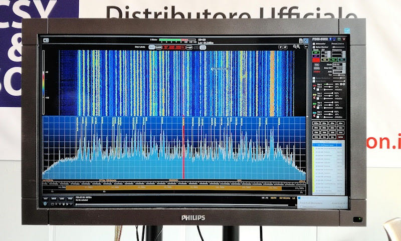
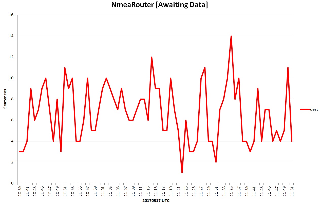
Below is a graph made using the excellent software by Neal Arundale – NMEA AIS Router. As you can see the message numbers (or sentences) for over an hour are pretty good – well, it is a vast improvement on what I used to get with my current “temporary” set-up, with 419 messages received in an hour. The software is available at his website, for free, along with various other programs that you can use with AIS. If you’d rather not use ShipPlotter he has created his own AIS Decoder which can be linked into Google Earth and such like. Visit his website for more information.

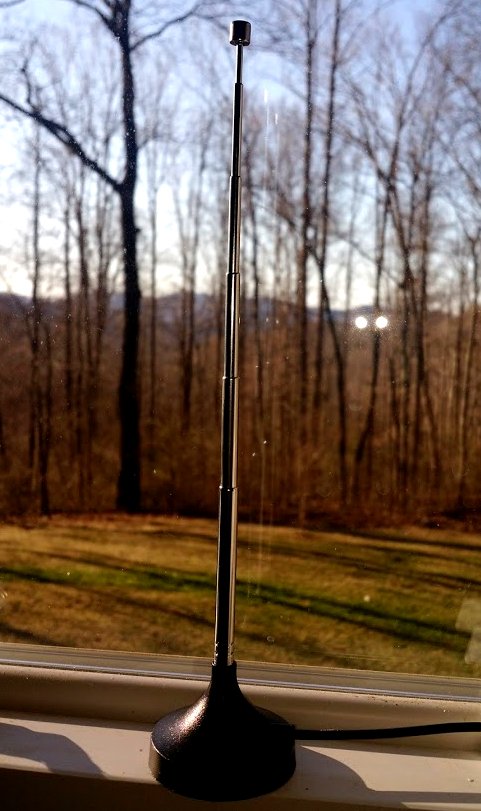
My antenna isn’t exactly top-notch. It is at a height of just 4 metres AGL in the extension loft, and it is made from galvanised steel angle bead used by plasterers to strengthen corners prior to skimming – this I cut down as a dipole for a target of 162 MHz. As usual with my trimming of antennas, I cut just too much off and ended up with it cut to 161.167 MHz. It gives a VSWR of 1.018 and Return loss of 40.82dB, with 162 MHz being approx. 30dB Return loss which equates to 1.075 VSWR – that will do.

Also, as I live right on the coast, about 50 metres from the sea, I’m practically at sea level, which doesn’t help much with range and signal reception either. Despite this the antenna produces great results, though it is just temporary until I can get a new homebuild up on the roof.

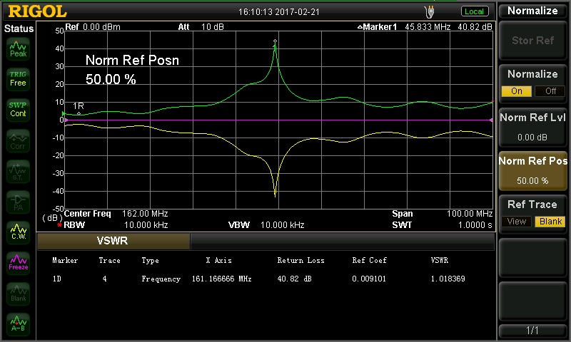
VSWR reading for the homebrew loft AIS Antenna

The LNA4ALL retails at various prices depending on what option you go for. I went for the aluminium box version so it was around £54 including the delivery. I had looked at a Mini-circuits equivalent, and when it looked like the LNA4ALL was lost I did actually order one. But this was nearly twice the price, and seeing as the LNA4ALL contains many components from Mini-Circuit I doubt it is any different really.

All in all the LNA4ALL is all you need to boost your weak signals – couldn’t get any more all’s in ?.


Many thanks for sharing your quick test of the LNA4ALL, Tony! Post Readers: if you’d like to read more of Tony’s work, check out his blog, Planes and Stuff.

More RadioShack store closing details including dates

Many thanks to SWLing Post contributor, Dave Zantow (N9EWO), who writes:

Here is a very interesting PDF legal document (via Prime Clerk) that not only has the “COMPLETE” RadioShack store list that are closing by early April (Tranche One and Two) but with important dates given.

Click here to download Docket 98-2 (PDF).

(more info: https://cases.primeclerk.com/generalwireless/Home-DocketInfo)

Yes, sadly the store I worked in for over 8 years is closing by (before) April 6th when this store will become Sprint only. Being in a Mall , its funny it was not closed in the first bankruptcy ?? It’s been in that spot since late 1981.

Many thanks, Dave. As I mentioned in this previous post, poor RadioShack is all but dead for us hobbyists and Makers–one last chance to grab some closeout deals before the retail outlets become Sprint stores.

TX Factor Episode 15

Many thanks to SWLing Post contributor, Thomas Ally, who notes that TX Factor have just published their 15th episode.

Here’s the episode description via TX Factor:

Bob gives a relaxed overview of the RS-BA1 remote control software for the Icom IC-7300. We meet two youngsters with a passion for amateur radio. And Mike and Bob head off to Bristol to spend a day with some very enthusiastic members of the British Amateur Television Club to learn all about digital amateur television.

Click here to view on YouTube.

Icom RS-BA1: Setting up the IC-7300 for remote operation

(Source: Southgate ARC and Dave Zantow)

New video: Icom RS-BA1. Installing & setting-up remote control for your IC-7300

The TX Factor have produced a video that logically goes through the step by step process of remote controlling an Icom Amateur radio, more specifically in this case, the IC-7300 using the RS-BA1 remote control software.

The video shows Bob McCreadie (G0FGX) of TX Films demonstrating:

• Setting up your computer and radio
• Installing the RS-BA1 remote control software
• Accessing the IC-7300 remotely
• Introduction to the RC-28 remote controller encoder.

To view this video visit: 
Icom RS-BA1. Installing & Setting up Remote Control for your IC-7300 SDR Radio

To found out more about Icom’s remote control software, visit the
RC-28 IP Remote Control System page where you will also find a list of compatible Icom HF radios.

For more information about the IC-7300 visit the
IC-7300 HF/50/70MHz Transceiver product page.

Both the RC-28 IP Remote Control System and IC-7300 are available from all authorised Icom Amateur radio dealers.

Of course, you could use the RS-BA1software to use the Icom IC-7300 as a remote shortwave receiver. Click here to read our review of the IC-7300.

Making a FlightAware ADS-B feeder with a Raspberry Pi 3 and RTL-SDR dongle

It’s been nearly a year since I acquired both the RTL-SDR (above) and Rasperry Pi 3 (below)r.

Remember when I made a plea for Pi 3 projects just last year––?

Although many of you suggested some great projects, I never actually got around to doing any of them. Now, don’t get me wrong––I wanted to, of course, but simply got involved with reviews, NPOTA, two months of travel…and, well, life.

Then, last week at the Winter SWL Fest, a common theme emerged in both presentations and discussions:  the numerous applications of the super-cheap, and thus super-ubiquitous, RTL-SDR dongle. In their engaging presentations, both Dan Srebnick and Mark Fahey––SWLing Post contributors and good friends––focused on the power of the RTL-SDR, expounding upon some simple, inexpensive applications in their forums. It was inspiring. Also, buddy Eddie Muro showed me just how easily an ADS-B receiver could be set up using an Android phone.

Back to the Pi. Though I was already aware the Pi 3 and RTL-SDR could be united to make an ADS-B receiver, watching Mark Fahey talk about how simply one could feed the FlightAware network with ADS-B data finally hooked me.  Why not, indeed? Here was fun to be had!

Mark preparing to woo his captive audience at the Winter SWL Fest!

I couldn’t get the idea out of my head, so Tuesday, the day following my return, I set the afternoon aside.  I rolled up my sleeves, and with my long-neglected Pi 3 and RTL-SDR, got ready to cook up a flight sensor.

I figured I was probably missing a component or two, and fully expected the process to be complicated, but decided I wouldn’t let this deter me. And guess what? I was wrong on both counts!

FlightAware ADS-B feeder recipe

Ingredients:

If you only plan to use this SDR and antenna as an ADS-B feeder, you might go for the FlightAware Dongle and 1090 MHz antenna combo.

Directions:

Note: I used this excellent PiAware ADS-B feeder tutorial to build my system–it’s detailed and doesn’t make the lofty assumption that you actually understand formatting cards, building disk images, and/or editing config text files.

Directions below are a highly distilled version of that tutorial. If you’re new to all of this, as I was, follow these directions instead of the above tutorial. Be aware that the directions assume you’re using the Pi 3 and a Windows PC to burn the image file.

  1. Download PiAware image7-zipSD card formatter, and the Win32 Disk Imager. Decompress all compressed files, install and note the folder locations.
  2. Register your username at FlightAware–presuming you don’t already have an account, of course.
  3. Use SD Card Formatter to format your MicroSD card.  Just make sure you’re formatting the correct drive, else you could easily wipe the wrong disk/card!
  4. Use Win32 Disk imager to write the PiAware image to your MicroSD card.
  5. If using WiFi, open Windows Explorer.  Locate text document called piaware-config on the MicroSD card, open it with a text editor, and locate the WiFi ssid and password locations. Per the config comments, edit them to match your WiFi system. Note that any special characters in both the name and password will require the use of quotation marks (again, noted in the config file comments). Save the file in the same location on the disc image.
  6. Remove the microSD card containing the PiAware image; insert it into the Pi 3.
  7. Connect the RTL-SDR or FlightAware dongle to the Raspberry Pi. Attach an appropriate antenna to the RTL-SDR. Note:  You’ll get the best results if you place the antenna outdoors with line of sight to the skies.
  8. Plug the Raspberry Pi 3 into a power source…and cross your fingers!
  9. Grab a cup of coffee, walk the dog, or listen to this 12 minute version of the BBC countdown; it could take at least this long for FlightAware to start receiving data from your ADS-B feeder.
  10. When you see this My ADS-B button in the header of FlightAware (see below), you’ll know you’re in business. Congratulations!  You can now watch the skies.

Feeding FlightAware

After my ADS-B receiver had been in operation for a while, I was very impressed with the data FlightAware was able to pull from my ADS-B feed. I was equally impressed with the number of distant aircraft I could receive with such a modest antenna––a number of them up to 135 miles from my location. Once I find a suitable outdoor location for the mag mount antenna, currently indoors, I expect the reception distance will increase significantly.

You can also connect to the live feed from your ADS-B receiver through your local network. Here’s a screenshot of my live data:

Future plans

At the moment, my ADS-B receiver is located indoors, in a south-facing window.

It works, but clearly isn’t ideal. Since the Pi 3 connects to my network via WiFi, I intend to install the full ADS-B receiver system into a small weatherproof case and mount it outside. My Pi 3 has no case, so I purchased an inexpensive one yesterday. I should be able to feed it power with an outdoor outlet…but I’m very tempted to experiment with making it solar powered.  To find out if this is a logical move, I need to observe and measure the power requirements first, and will be doing that in the next few weeks.

Meantime, I’m thoroughly enjoying watching the (amazingly busy) traffic in the skies…and the kid in me relishes it!

Thanks, Mark, for the great idea!

Have any SWLing Post readers attempted to build a solar-powered or outdoor ADS-B receiver? Please comment!

Photo of the new Elad FDM-S3

Many thanks to SWLing Post contributor, Rafman, who shares the following photos that were originally posted by Alberto (I2PHD) on the Elad email reflector. Alberto noted:

“Here it is…. shown for the first time today at the Montichiari Ham Fest. Price TBD….”

Many thanks, Rafman, for the tip!

We’ll continue to post FDM-S3 updates as they become available. I will also plan to review the FDM-S3 when it hits the market.

Click here to view the Elad website.

Cornell engineers invent two-way radio on a single chip

Many thanks to SWLing Post contributor, Tom Ally, who shares the following news via the Cornell Chronicle:

Engineers devise two-way radio on a single chip

Two-way communication requires, of course, both send and receive capabilities. But putting them in the same device requires a filter between the send and receive circuits to provide signal isolation.

Without a significant filter, communication would be impossible.

“Your transmit signal is [10 to the power 14] times stronger than your receive signal,” said Alyosha Molnar, associate professor of electrical and computer engineering (ECE). “That’s 100 trillion times stronger – that’s a really hard problem.”

But researchers in Molnar’s lab have offered up a solution.

Molnar and collaborator Alyssa Apsel, professor of ECE, have devised a method for both transmitting and receiving a radio signal on a single chip, which ultimately could help change the way wireless communication is done.

Their work is described in “A wideband fully integrated software-defined transceiver for FDD and TDD operation,” published online Jan. 27 in the Institute of Electrical and Electronics Engineers’ Journal of Solid-State Circuits. Doctoral student Hazal Yüksel and Dong Yang, Ph.D. ’15, are co-lead authors.

Separating the send and receive bands is difficult enough, but the problem is compounded by the ever-increasing number of bands in the latest devices. From GPS to Bluetooth to Wi-Fi, each band requires a filter to stop the strong transmit signals from drowning out reception.

Molnar and Apsel have come up with an ingenious way to separate the signals. Their idea lies in the transmitter – actually a series of six subtransmitters all hooked into an artificial transmission line. Each sends its signal at regular intervals, and their individually weighted outputs are programmed so that they combine to produce a radio frequency signal in the forward direction, at the antenna port, while canceling out at the receive port.

The programmability of the individual outputs allows this simultaneous summation and cancellation to be tuned across a wide range of frequencies, and to adjust to signal strength at the antenna.

“In one direction, it’s a filter and you basically get this cancellation,” Apsel said. “And in the other direction, it’s an amplifier.”

“You put the antenna at one end and the amplified signal goes out the antenna, and you put the receiver at the other end and that’s where the nulling happens,” Molnar said. “Your receiver sees the antenna through this wire, the transmission line, but it doesn’t see the transmit signal because it’s canceling itself out at that end.” […]

Continue reading on the Cornell Chronicle.