Category Archives: Radio Modifications

James put his ailing Sony ICF-SW55 on ice. Literally.

sony-icf-sw55c

Many thanks to SWLing Post contributor, James Patterson, who writes:

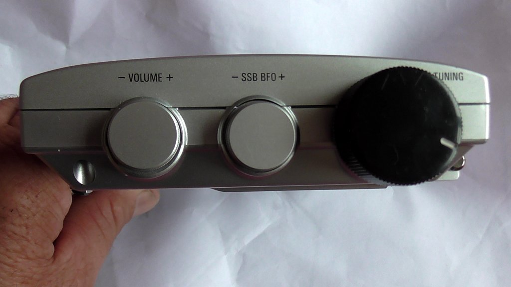
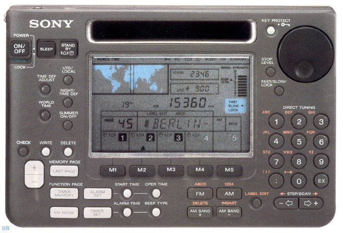
I have owned the Sony ICF-SW55 for around 15 years or more. I like to change my listening pleasure from radio to radio, giving each one a rest, as they are all different to a degree. So I put the SW55 away and it sat unused for about six moths, as with my radio collection, I had others to listen to.

But when I decided to listen to the SW55 again, it just wouldn’t power up at all. I have read posts from other listeners saying their radios won’t power up either after sitting for extra long periods. I think they are mostly Sonys.

I tried many times but no it wouldn’t power up; I decided I’d just keep it as a memory of a failed Sony radio. I’m aware that the capacitors do blow, and assumed that’s most likely the problem.

But I decided there may be another way to get it going again. I always check for [battery compartment] corrosion, but there was none.

I thought of a crazy idea of actually freezing the radio–just to see what may happen. So it was in the chest freezer for 3 hours. I then took it out frozen like an ice brick!!.

I took it outside to the blazing hot sun and let it fully defrost. I then plugged a DC power pack into it. The operating voltage is 6 volts. I pushed 9 volts into it, through the switchable power pack. I got a plastic clamp and clamped the on/off switch permanently “on”.  I could hear it turning on and off several times as the switch is electrically-activated.

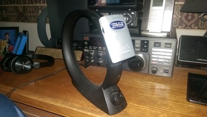
Then all of a sudden it sprang to life–unbelievable! On it came at full volume, so I selected an AM station and it worked as good as it ever did. The sensitivity was always very good, and it still is.

So was it a “Fluke”, “freak of nature” just by chance, or was it the freezing that woke it up?

Well I’m not turning it off. I have new AA batteries in it, as well as the power pack that’s turned back to the correct 6 volts–and yes it’s still going!!

So maybe we should all start freezing our radios when they have given up the “ghost”!?! Don’t forget to defrost before powering up!! Maybe I’ve started a “new trend”. Any comments would be great! Thanks.

Thanks Thomas and have a great and happy New Year from New Zealand.

Wow–James, I’m not sure why this freezing method worked, but I’m glad it did!

I don’t think I could recommend that everyone try this but, James, you did this out of desperation since you essentially had a nice ICF-SW55 paperweight. What did you have to lose? I’m very curious if some engineers or electronics technicians could comment as to why freezing the radio helped.

I do know this: I would be cautious attempting James’ freezing method if you live in a humid environment. It’s possible that the condensation from the radio thawing could actually cause moisture damage. Obviously, in James’ case, it did not.

Thanks again, James–I hope your ICF-SW55 gives you many, many more years of service!

Icom IC-R72: a repair story

Icom-IC-R72-Front-Mehdi-Asgari
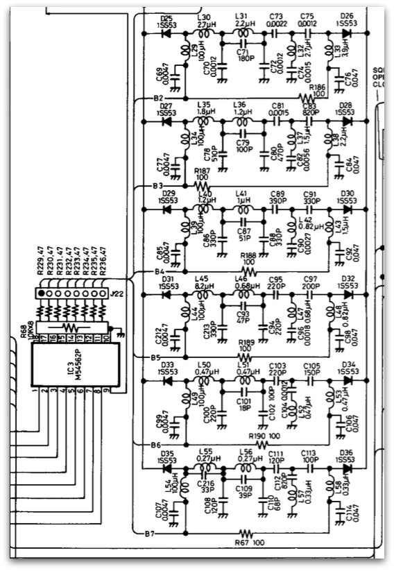
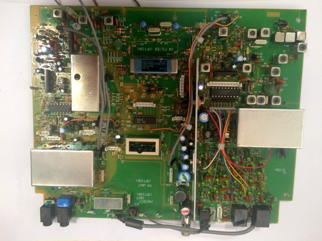
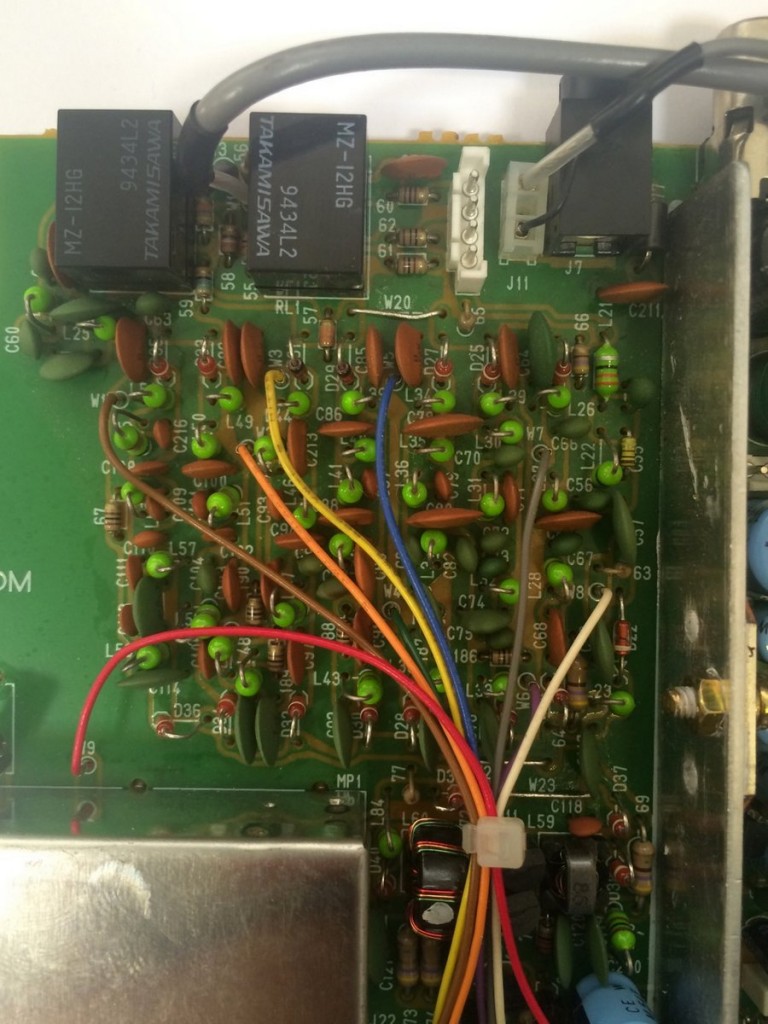
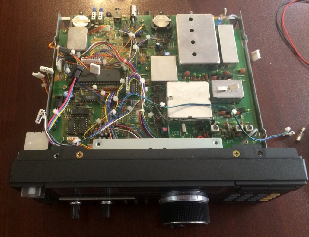
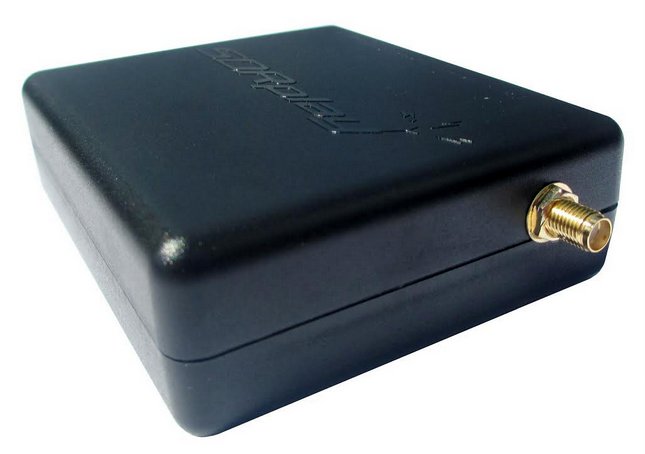
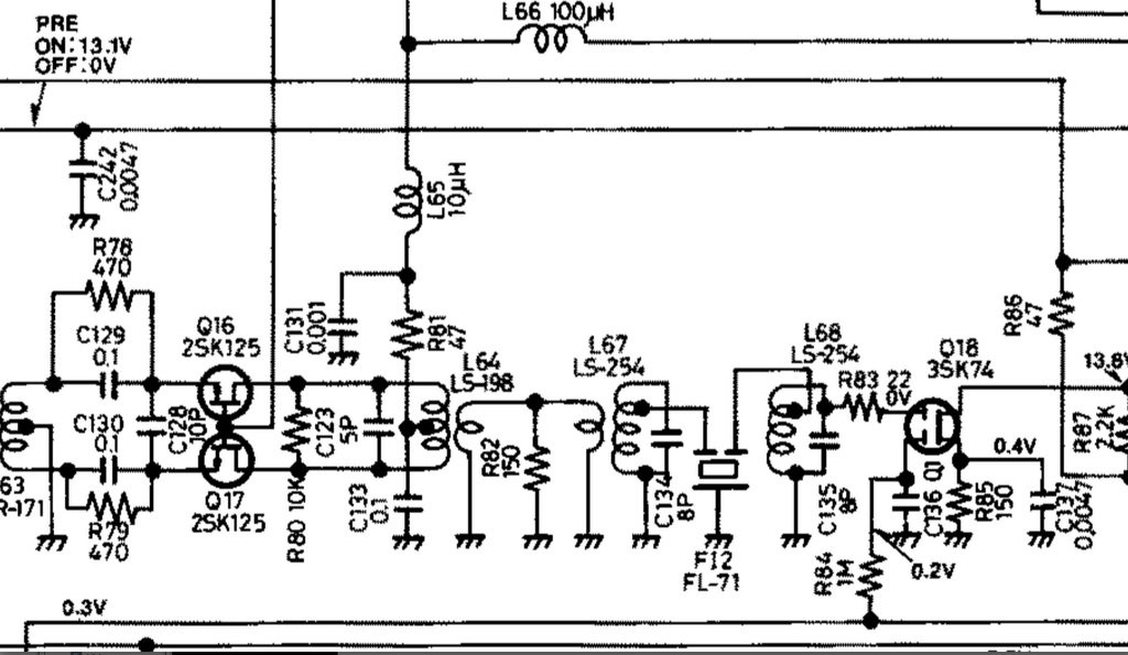
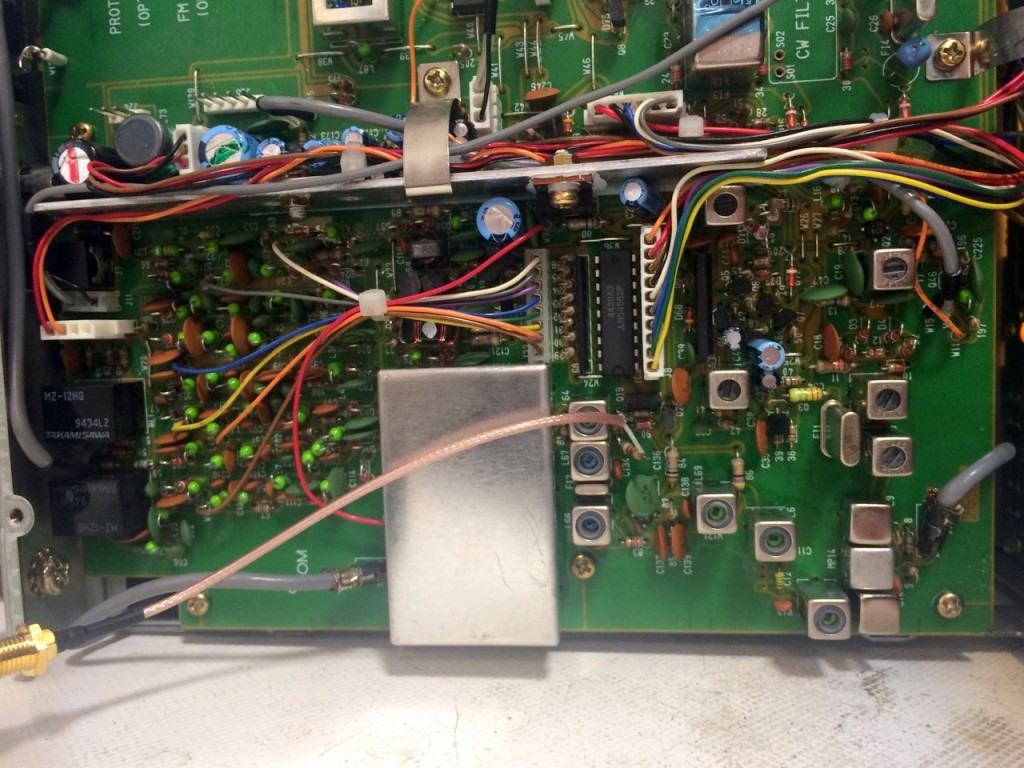
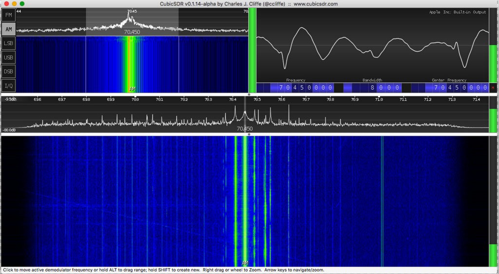
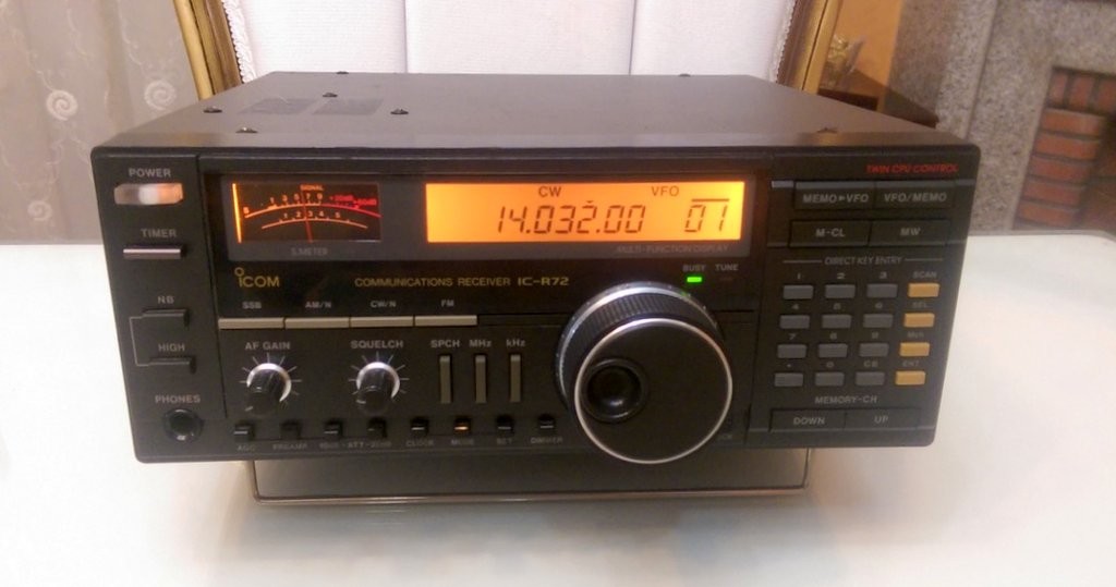
In this post I’m going to tell you how I repaired my Icom IC-R72 receiver. Although it’s about a specific device, the logic and methodology applies to all radios.

I bought an Icom R72 from a friend for about $200. At first, I just checked 7.0MHZ (40 meter band) and 21.0MHZ (15 meter band) and it was OK. After some time, I tried to listen to some ham radio on 20 meters (14.0MHZ) and it was deaf! I checked everything: antenna connectors, balun…everything.

With some trial and error, I found out that it was deaf from 11-15 MHz. With the help of the members of “Icom R72” Yahoo Group, I found one of the usual suspects: bandpass filters’ switching diodes.

I took a look at the service manual and apparently this radio uses multiple bandpass filters  for different  frequency ranges.

Schematic-Icom-R72-1

As you see in the above picture (grabbed from service manual), one of the bandpass filters is for 11-15 MHz range–that’s the range where my radio was deaf.

Note that there are multiple ways to test that a radio is deaf at a frequency. One of the simplest ways: connect an antenna or even a long wire to the antenna socket of radio. The noise level should increase; if not, there’s a problem.

Schematic-Icom-R72-2

After testing diodes with a multimeter, I found out that D31 is faulty. Almost all multimeters have a diode-test functionality.

I replaced it. The original diode was 1SS53, but I used a 1N4148 which is very common and found everywhere. Now I have a working radio! 🙂

If you have a radio that’s deaf at a frequency range, there is probably a problem in bandpass filters.

Here are some internal pictures of my Icom IC-R72:

IC-R72-Internal-IF-Stage-Mehdi IC-R72-Board-1 IC-R72-Board-2 Icom-IC-R72-Open

I should thank my friend and electronics mentor, Saeed (EP2LSH) who always helps me in my electronics adventures.

Mehdi Asgari, the author of this post, is a regular contributor to the SWLing Post. Mehdi lives in Tehran and is an active member of the EP2C amateur radio club.

How to use the SDRPlay RSP as a panadapter

SDPlay-RSP

In this post, I will show you how to use an SDR as a panadapter for a commercial communications receiver. I’m using an Icom R72 and a SDRPlay RSP, but you can do it with nearly all receivers and SDRs.

The Icom R72 is a double conversion HF (0-30 MHz) communications receiver.

A panadapter lets you see the spectrum of your receiver (it gives you a broader, higher-level picture of what’s around your tuned frequency). After using it, you’ll wonder how you’ve been using your receiver without a spectrum display! 🙂

Almost all the radios we use are of superhetrodyne type. To connect a SDR to the radio, you should first find its 1st IF mixer output (if it has more than one Intermediate Frequency stage).

To find it, the best way is to consult the service manual. The first IF of Icom R72 is 70.4500 MHz, so we can use RTL-SDR dongles too.

Here’s a part of R72’s schematics, extracted from its service manual:

IC-R72-Schematic-Mehdi-Asgari

Look at the R82 resistor; it’s located at the output of first IF stage, so I soldered a connector to its pins (its other pin is connected to the ground)

Between the R82 resistor and the output, we’ve added a series 470-ohm resistor (to prevent loading the IF stage)

IC-R72-Internal-IF-Stage-Mehdi

Click to enlarge.

The other side of this connector is connected to the antenna input of my SDRPlay RSP.

Now I can view my spectrum on a PC.

Here’s a screenshot of CubicSDR on Mac OS X (you can use other apps like HDSDR, SDR Console, etc.):

CubicSDR-Screenshot-Mehdi

Although this post was about the SDRPlay RSP and Icom R72, this procedure can be done for almost any combination of receivers and SDRs provided that your SDR covers the frequency of first IF stage.

Also, don’t forget that you should tune the SDR to the frequency of IF–in this case: 70.4500 MHz.

Mehdi Asgari, the author of this post, is a regular contributor to the SWLing Post. Mehdi lives in Tehran and is an active member of the EP2C amateur radio club.

Best solution to restore a vintage plastic radio chassis?

Sony-ICF550W-FrontFriday, I brought home an untested, slightly grimy, Sony ICF-5500W. I purchased it through Goodwill for $20.

Sony-ICF550W-Right

I crossed my fingers as I put three C cells in the radio and turned it on. Fortunately, I was rewarded with brilliant audio. I tuned the ‘5500W on AM/mediumwave and heard CFZM,  500 miles to my north, and Radio Reloj, 860 miles to my south. A quick scan on the FM dial revealed that I could also hear all of my local benchmarks. Whew!

Other than the dial needing a little calibration, and DeOxit on a few pots, it’s in excellent mechanical shape.

Sony-ICF550W-Left

I started cleaning the radio last night using Q-tip cotton swabs and a vinegar/water solution.

I’d like to restore the hard plastic chassis’ original shine, though.

I was tempted to reach for some Armor All, but stopped myself short. I know it would give the ICF-5500W a nice shine, but would it cause any long-term damage to the black plastic or clear dial cover?

I know there are vintage radio restorers among the SWLing Post readership. Can someone offer advice on what’s the best product to use (or not use!) on my ICF-5500W?

If you have experience, please comment!

Jeff’s solution to increasing FM performance on the Sangean U3

Sangean U3

Many thanks to SWLing Post contributor, Jeff McMahon (at the Herculodge), who writes:

I upgraded my Sangean U3 with a male to female iMBAPrice 6 foot stereo audio extension cable 3.5mm, which I plugged into the U3’s auxiliary port.

Sangean U3-1

The U3’s small stub of an FM antenna really needed some extra oomph. Now my U3 is picking up all my favorite stations, including the problematic KPCC 89.3 in Pasadena.

AM is as great as always. The sound is crystal clear on AM and FM. If this radio weren’t so big, I’d buy two more for the kitchen and my bedroom, but will have to be content to have one for my gym/office radio.

Sangean U3-2

Thanks, Jeff! I might have to consider the Sangean U3–I hope a reader will let me know if one goes on sale.

Like Jeff, having a radio that not only performs admirably, but that can also withstand the attention of my kids, may be a great investment over the long-term! I’m glad such a simple addition to the U3 means that you can now hear your favorite Fm station, Jeff!

Now if Sangean only made a shortwave version of the U3–!

Simple hack: Changing the tuning knob on the PL-660

Tecsun PL660 modified Tuning knob 001

Many thanks to SWLing Post contributor, James Patterson, who writes:

Has anyone ever thought of changing the Tuning knob on the PL-660?

Putting a larger knob on it makes for much easier turning instead of the very small fiddly knob Tecsun supply.

Tecsun PL660 modified Tuning knob 002

Finding the right plastic knob maybe a problem, needing to insert it over the tuner cam. But modifying another knob off something else is what I did.

Tricks of the trade!!

Tecsun PL660 modified Tuning knob 003

That looks like a very simple and effective mod, making the 660 more tuner-friendly for you! Thank you for sharing, James!

Bill’s simple Sony SRF-59 passive loop antenna modification

Sony-SRF-59-AM-Loop-Antenna

In reference to our previous posts about the Sony SRF-59 ultralight receiver, SWLing Post reader, Bill Mead, writes:

“As someone who doesn’t normally open the backs of radios, this is my mod on my ultralight. All it takes is a bit of electrical tape to hold the belt clip on the loop.”

That is, indeed, a brilliant and simple mod. The SRF-59 inductively couples to the loop antenna, so no soldering is needed; simply tape the belt clip to the loop, making sure the position is convenient for tuning the SRF-59 and the loop’s capacitor.

You can find passive loop antennas ranging from $19 to $50 US. The Grundig AN-200 and the Terk AM Advantage are two models currently on the market. Here are a few places you can check prices:

Grundig AN-200:

Terk AM Advantage: