 Many thanks to SWLing Post contributor, Matt Blaze, for the following guest post:
2022 rooftop receiver shootout
by Matt Blaze
I realized it’s been long past time for me to do another head-to-head receiver comparison “shootout”, where you can compare the audio from multiple radios receiving the same signal at the same time. Long time readers of Thomas’ blog may remember I’ve posted a few of these before.
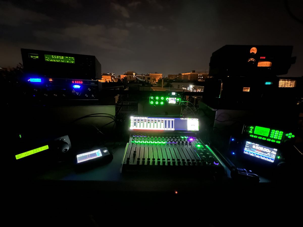
So I took advantage of the nice weather and brought a bunch of radios, recording gear, and an antenna up to the roof to listen and record signals under an open sky. My neighbors, no doubt, wondered what I must have been up to. (Don’t tell them I’m just a harmless radio nerd.)
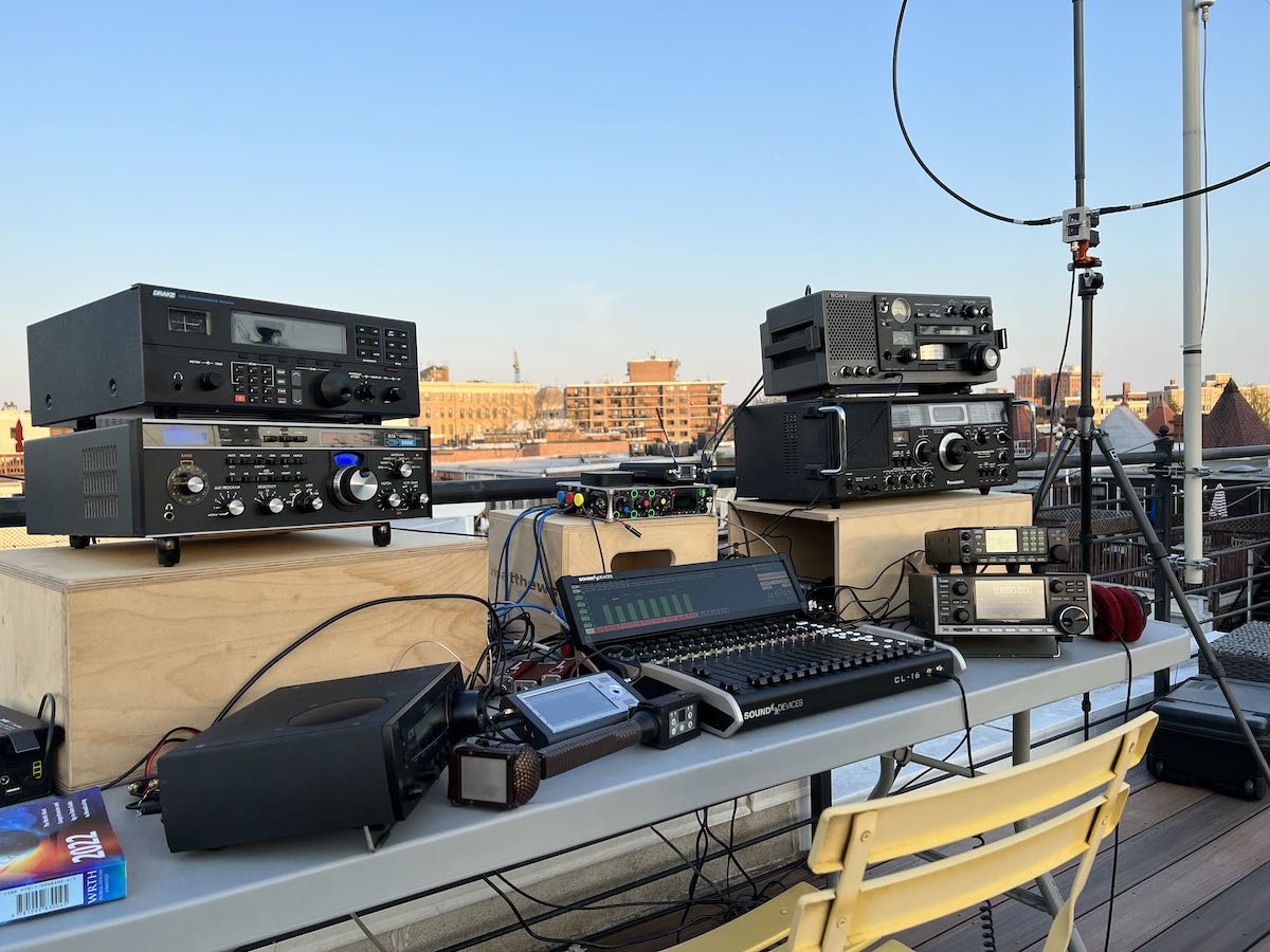
This year, our focus is on eight “dream receivers” from the 1980’s to the present. Each radio is at or near the top of the line in its class at the time of its release. Our radios include, in roughly reverse chronological order:
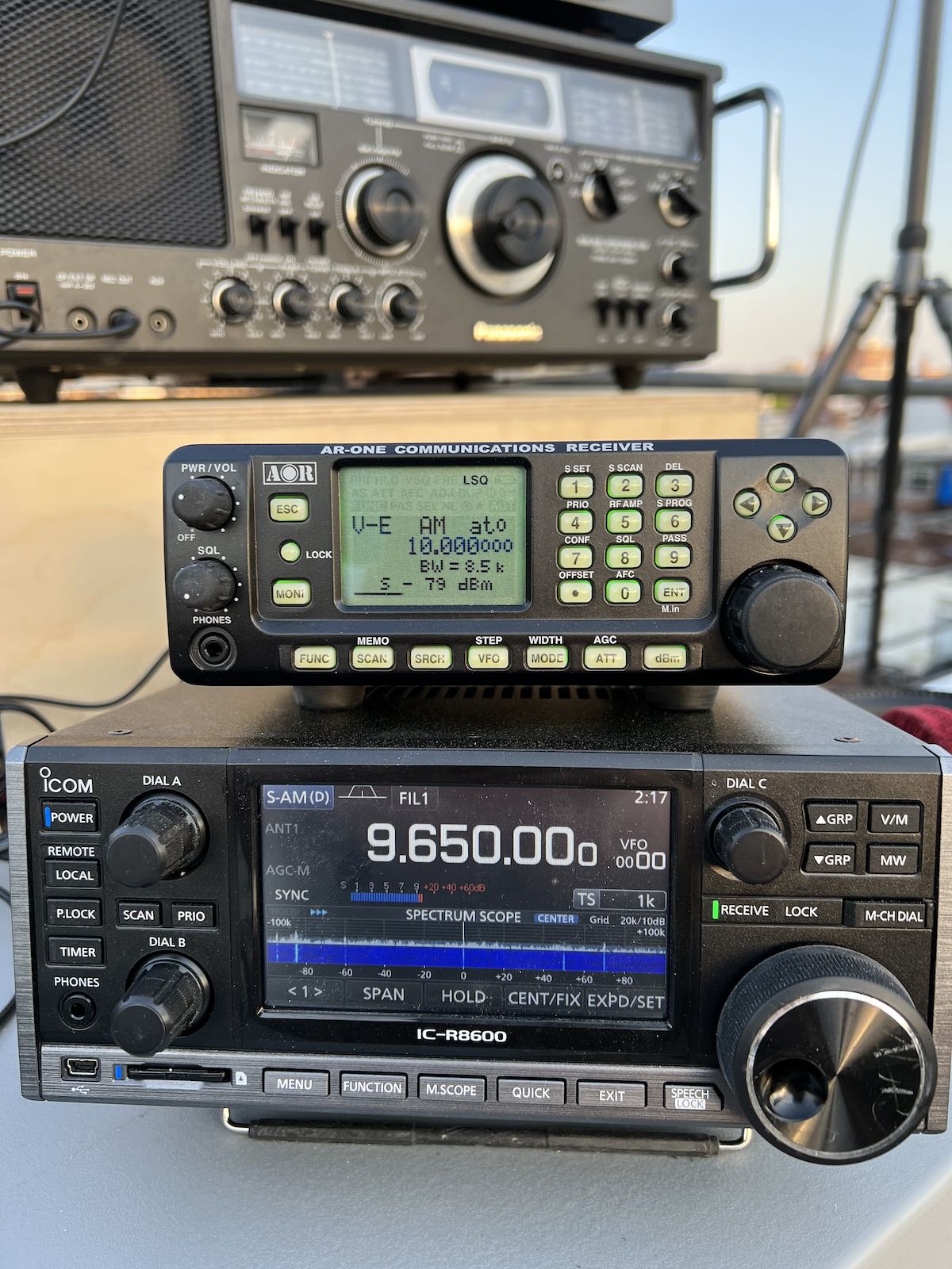
- Icom R-8600, a current production “DC to Daylight” (or up to 3 GHz, at least) general coverage communications receiver, with highly regarded shortwave performance.
- AOR AR-ONE, another DC to Daylight general coverage radio, less well known due to the high price and limited US availability. Excellent performer, but a terrible (menu-driven) user interface for shortwave, in my opinion.
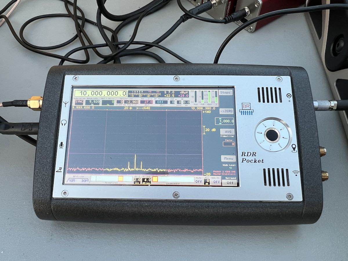
- Reuter RDR Pocket, a very cute, if virtually impossible to get in the US, small production, high performance SDR-based shortwave portable receiver. It’s got an excellent spectrum display and packs a lot of performance into a surprisingly small package.
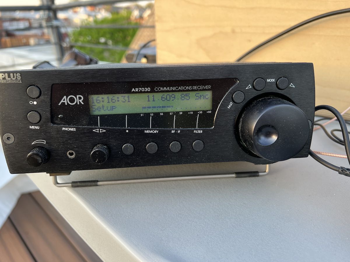
- AOR 7030Plus, an extremely well regarded shortwave receiver from the late 90’s; designed in the UK. It’s got a quirky menu-driven user interface but is a lot of fun to use.
- Drake R8B, the last of the much-beloved Drake receivers. Probably the chief competitor to the 7030.
- Drake R7A, an excellent analog communications receiver (but with a digital VFO) from the early 80’s. It still outperforms even many current radios.
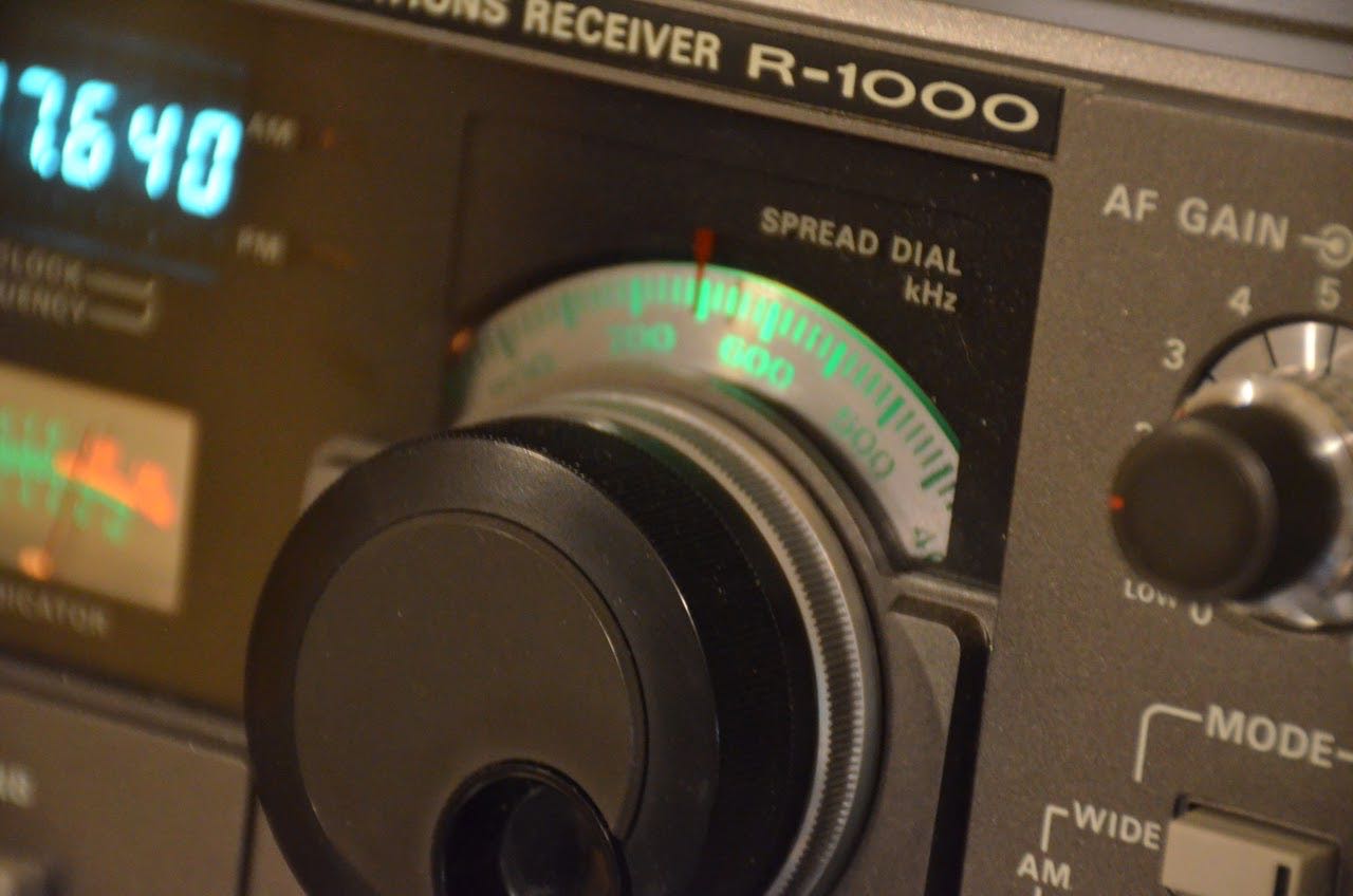
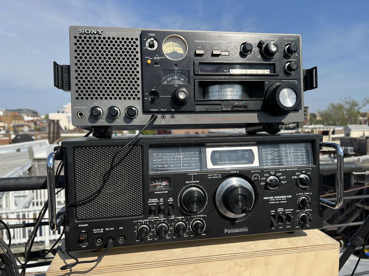
- Sony ICF-6800W, a top of the line “boom box” style consumer receiver from the early 80’s. Great radio, but hard to use on SSB.
- Panasonic RF-4900, the main competition for the Sony. Boat-anchor form factor, but runs on batteries. Excellent performer, but also hard to use on SSB.
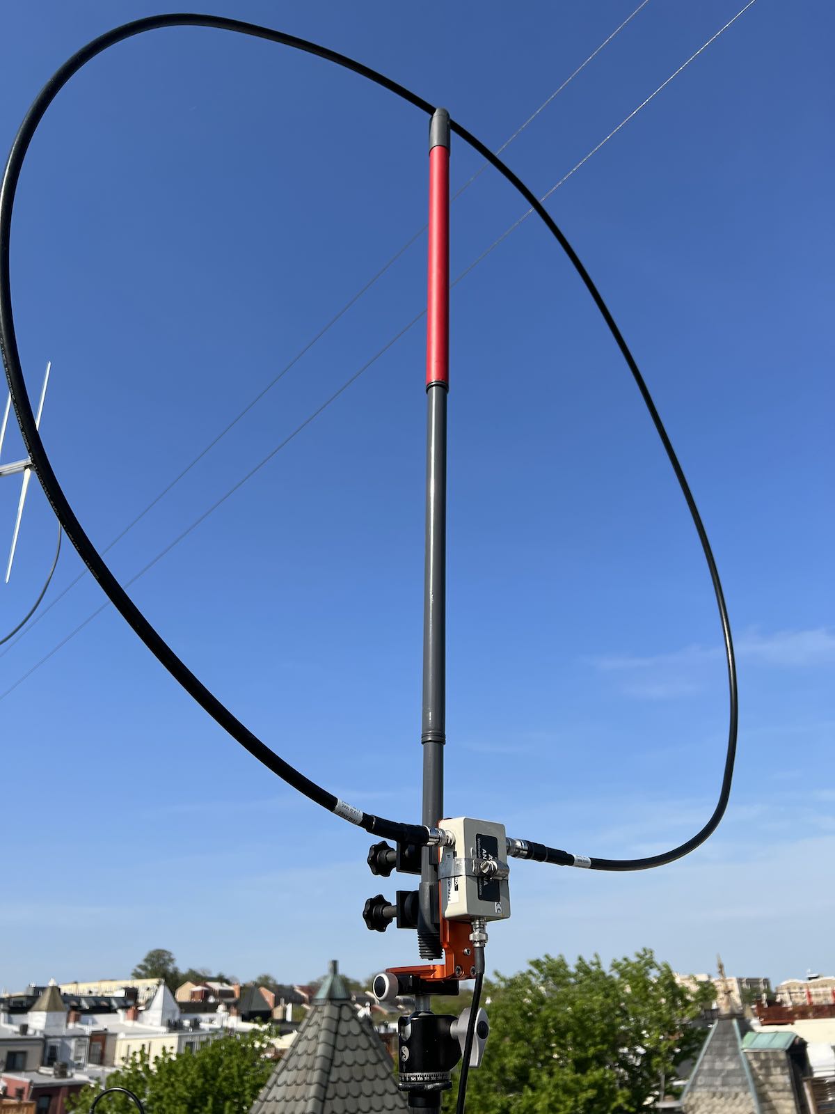
The radios were fed from my portable Wellbrook FLX-1530 antenna, using a Stridsberg Engineering HF distribution amplifier. So every radio was getting pretty close to exactly the same signal at its RF input.
Recordings were taken from the line output, if one was available, or the external speaker/headphone output otherwise. In either case, the audio was then isolated and converted to a balanced signal for recording.
For each signal, I recorded monaural “solo” tracks for each radio, as well as a narrated stereo track in which I compared the audio from each radio (one after the other) against the Icom R8600, with the audio from the R8600 on the left channel and the audio from the other radios on the right channel. This gives you a quick overview of what all the radios sound like.
The stereo recording requires some explanation. For it to make any sense, you MUST listen in stereo, using decent headphones if at all possible. You can switch earpieces back and forth (with your finger on pause and rewind) to get a quick idea of what each radio sounds like compared with a modern receiver, and how they handle things like fades and static.
The solo tracks, on the other hand, consist entirely of the continuous audio from a single radio, with no narration or interruption.
I recorded three different signals, for a three part comparison. (Parts four and up will come, hopefully, soon). I think both the differences and similarities will surprise you.
Part One
 Our first signal was the BBC on 9915 KHz, broadcasting from Madagascar to western Africa. This signal was extremely marginal here, intended to show how each receiver can or can’t handle signals down in the noise. It’s definitely not “armchair copy”.
The stereo overview is at:
The individual receiver solo tracks can be found here:
Icom R-8600:
AOR AR-ONE:
Reuter RDR Pocket:
AOR 7030Plus:
Drake R8B:
Drake R7A:
Sony ICF-6800W:
Panasonic RF-4900:
Part Two
 Our next signal was the Shannon (Ireland) aviation VOLMET broadcast on 5505 KHz USB. This synthesized voice gives the latest meteorological conditions at airports around Europe. The signal was not strong, but entirely readable. It shows how the radios handle a weak SSB signal. Note that the Sony and Panasonic consumer radios, though equipped with a BFO, were VERY hard to tune properly.
The stereo overview is at:
Receiver solo tracks can be found here:
Icom R-8600:
AOR AR-ONE:
Reuter RDR Pocket:
AOR 7030Plus:
Drake R8B:
Drake R7A:
Sony ICF-6800W:
Panasonic RF-4900:
Part Three
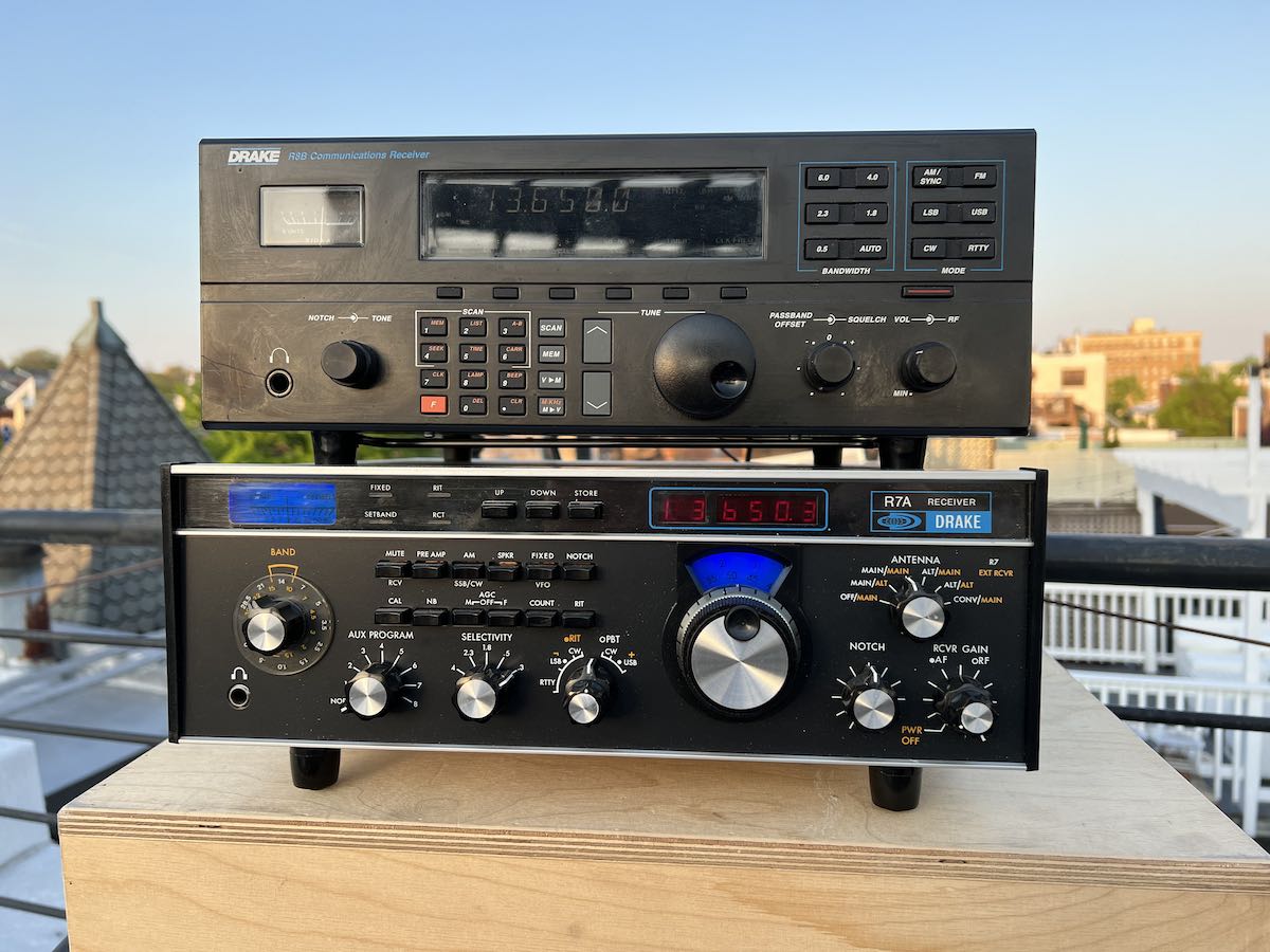 Our final signal was a stronger, though occasionally fading, shortwave broadcaster, Radio Romania International on 13650 KHz AM. This gives you a sense of how the receivers performed on a typical “average” signal that you might actually want to enjoy listening to. Because the radios have different filters and other capabilities, I tuned each radio to whatever sounded best; I did not attempt to use comparable settings (since no common settings existed).
The stereo overview can be found at:
And the individual solo tracks are here:
Icom R-8600:
AOR AR-ONE:
Reuter RDR Pocket:
AOR 7030Plus:
Drake R8B:
Drake R7A:
Sony ICF-6800W:
Panasonic RF-4900:
Subsequent comparisons, hopefully soon, will focus on receiver performance on signals in crowded bands and under various kinds of interference and noise.
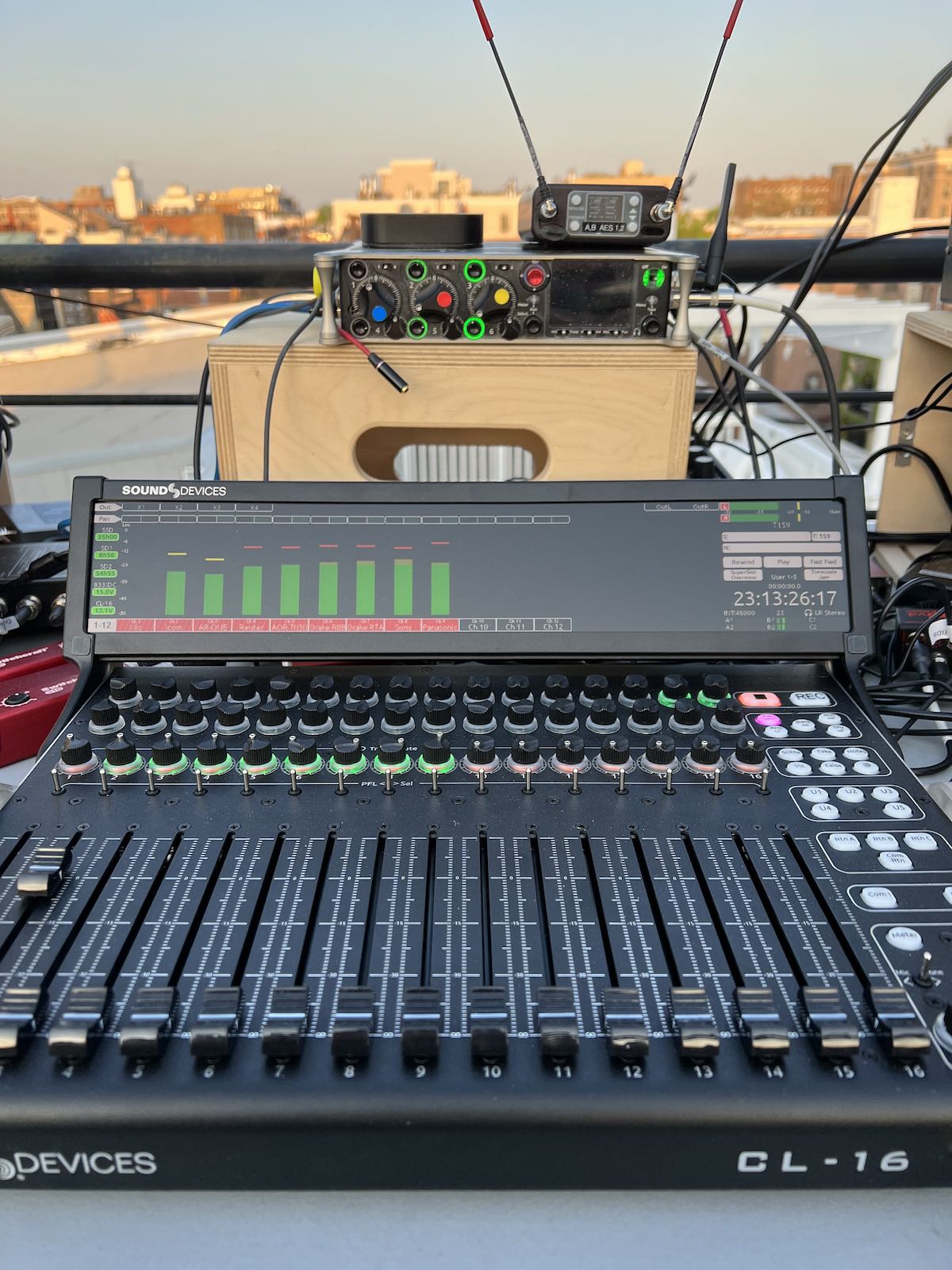
A quick note on production: The recordings were made with a 12 channel Sound Devices 833 recorder with a Sound Devices SL-16 mixing console. The audio was isolated and converted to balanced output with Switchcraft 318 direct interface boxes (highly recommended for recording radios with pro audio gear).
The stereo track narration was done by me in real time, as the signals were being recorded. I made some comments about which receivers I thought sounded best that were not always the same as what I would later conclude after carefully listening to the solo tracks once back inside. But judge for yourself. I used a Coles “lip” microphone, an amazing ribbon mic designed decades ago for the BBC for use in highly noisy environments. It was very effective in reducing the sometimes considerable street noise and other ambient outdoor sounds.
Thanks for listening and 73!