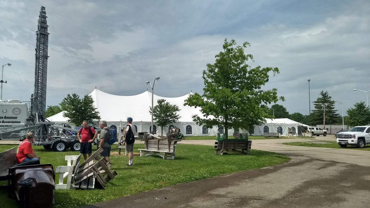
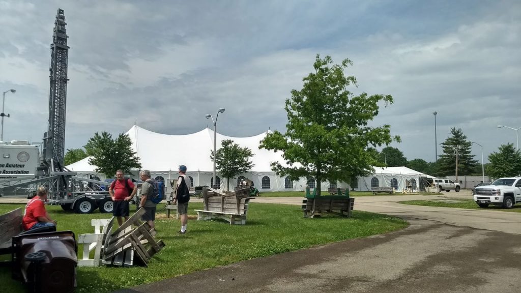
Category Archives: Ham Radio

Ham Radio Friedrichshafen 2018 Vendor Photos

Many thanks to SWLing Post contributor, Mehdi Asgari (DF2HF / NM9A), who shares photos from the Friedrichshafen ham radio convention this year. Tomorrow, we’ll post his photos of the flea market area!


Ham Radio Friedrichshafen 2018

by Mehdi Asgari (DF2HF)

Mehdi is a software engineer and SDR lover working in Berlin. He’s a licensed ham (DF2HF & NM9A) and also a member of EP2C club.

Spread the radio love

The evolution of a radio shack…and parting ways with my Elecraft K2/100

[Update: One of our readers purchased the K2/100! Thanks!]

I freely admit it: a lot of radios enter and exit my radio shack––especially portable receivers and SDRs of all stripes.  It’s just the nature of doing gear reviews and evaluations. I also keep a fairly robust arsenal of radios here at SWLing Post HQ for future comparison reviews and evaluations as models are upgraded.

But amateur radio transceivers that I personally use at home and in the field––? These come and go much less often.

I feel lucky in that I get exposure to most of the radios currently on the market. Yet I’m also cursed in that I simply can’t turn off that internal reviewer when I use a radio! I’ve become a bit extra-critical, hopefully constructively so, of radio ergonomics, user interfaces, functions, and of course, performance.

I used to have a healthy selection of transceivers in my shack as well, but over the years I’ve found it necessary to distill them down to just a few––almost all of which, if you’re curious, are Elecraft models.

My Elecraft KX1 in the Pelican 1060 case which fit it and its accessories perfectly.

One of the first Elecraft rigs I owned was the KX1, the ultimate handheld field portable 4-band CW radio of its time. I believe I acquired it in 2008. SWLs will be interested to know that I could even tune to broadcasters on the KX1, using ECSS.

The Elecraft K1 (Source: Elecraft)

I loved the KX1 so much, in fact, shortly thereafter I purchased a K1.  The latter I ended up keeping for perhaps one year or so.

Soon thereafter, I purchased an Elecraft K2/10 (the “/10” stands for 10 watts).

I should note here, for those who are not familiar, that almost all of Elecraft’s products are available in kit form. The K1, KX1 and K2 are proper kits. You can’t buy them factory built at Elecraft. With that said, I’ve never had the pleasure of building any of these models from kit form because I purchased them second hand.

The Elecraft K2

The K2 has been in production now for twenty years (!!!) and it still has a healthy market and dedicated community. The K2 must be one of the best documented, benchmark performance through-hole kit transceivers ever made. Because of the robust user base and the fact Elecraft still produces it, it’s also one of the easiest radios on the market to diagnose and repair. The thing was designed to be a “hands-on” radio–to be pulled apart and serviced–there’s no mystery meat inside.

I used my K2/10 for many years…and assured myself I’d never sell it.

Grundig G3 shortwave portable (left), Elecraft KX3 general coverage transceiver (right)

Ah, the best laid plans of mice and men…! In 2011 Elecraft introduced the venerable KX3 and I fell head over heels for that radio (just read my review). All of a sudden, my trusted K2/10 wasn’t getting as much air time and started collecting dust, so I (reluctantly) sold it to free up some radio funds.

Then, within weeks of selling my K2/10, someone posted a K2/100–a 100 watt version of the K2–for sale on our local radio club’s email group. No one in the group showed interest. The sale was for a late local ham, now SK (silent key), and his friend who was selling off the equipment really wanted to unload it quickly for the benefit of his family. I expressed interest, and only two weeks after selling my K2/10, I was a K2/100 owner.

I figured this must be the universe intervening because, had I not sold the K2/10, there’s no way I would have had funds to purchase the K2/100.

After purchasing the K2/100, I sold my only other 100W rig:  my beloved Ten-Tec OMNI VI+. I had been the owner of the OMNI VI+ for more than a decade and it was a radio I dreamed about in the 1990s. Still, it took up way too much table space in my modest little shack and, yet again, I needed to consolidate.

Activating PK01 (The Appalachian Trail) with the KX2 during the amazing National Parks On The Air event.

Fast forward a few years to the day before the 2016 Hamvention:  Elecraft announced their new field portable radio, the Elecraft KX2. The Elecraft team gave me early access to the KX2 and once again, I was head over heels for this new rig. When I started my review of the KX2, I already knew I wanted one, so didn’t even bother reaching out to Elecraft for a loaner––I just bit the bullet and purchased it. Click here to read that review. Shortly after making this purchase, I sold my KX1.

If you’ve been keeping track thus far, you’ll note that I currently have: an Elecraft KX3, an Elecraft KX2 and an Elecraft K2/100.

You’d think I was an Elecraft fan, but that’s not entirely the case. Elecraft KX series transceivers simply suit my operating style and meet my performance expectations. Why?

  • excellent ergonomics
  • benchmark performance (just ask Rob Sherwood)
  • general coverage SW broadcast reception
  • accessible, friendly customer service
  • regular updates and upgrades
  • and brilliant portability!

Recently, I’ve come to realize that although I still love the K2/100 in so many respects, I reach for my KX3 and KX2 more often…even though the K2 is my only 100-watt transceiver.

For this reason, I’ve decided I must sell the K2/100 so that I can fund the purchase of the (rather pricey) Elecraft KXPA100 amplifier. With the KXPA100, both my KX3 and KX2 will have a 100-watt linear amplifier at their disposal. Integration is seamless, and the amplifier is quite portable. With the KXPA100, I’ll be able to run a “full gallon” on Field Day on two radios I know like I know the back of my hand (especially the KX2!).

It has the latest firmware and includes all modifications. It’s fully-loaded, too–here are the options:

  • KPA100 K2/100 Internal Integration Kit
  • K160RX 160M and 2nd RX port
  • KDSP2 SSB Adapter (which is now discontinued)
  • KNB2 High Performance Noise Blanker
  • KSB2  SSB option

The only option it lacks, as far as I can tell, is the K60XV (60M and transverter adapter).

I’m hoping to sell the K2/100 for about $900 shipped (unless you, gentle readers, advise otherwise).

My K2/100 will be on view at the Winston Salem, NC hamfest this weekend, where I plan to hold down a table with my buddy, Vlado (NC3Z). I doubt I’ll sell it there, so will likely post it online later.

Here’s the thing, though…I look at this awesome little radio and wonder why I’m selling it! And then I close my eyes….take some deep breaths…and remember that it’s all about consolidating the shack and maximizing the potential of the KX3 and KX2.

And, who knows? Maybe the universe will intervene once again, and I’ll own another K2 in the future.

Post Readers, weigh in:  What radios have you bought and sold?  Any regrets?  Which have been, or are still, your favorites––and why?

Spread the radio love

TX Factor Episode 21

(Source TX Factor)

Welcome to our latest episode!

We hope you like the new theme tune!

In this early summer episode we look at programming your DMR handie and running a SharkRF openSPOT digital radio IP gateway. We review the new Icom IC-7610 transceiver, and Mike visits Bob’s shack in Cornwall to learn more about operating through linear satellites.

In our free-to-enter draw, there’s a chance to win two great amateur radio-related items. How about a Prism protective dust cover for your rig and a copy of Andrew Barron ZL3DW’s bookAmsats and HamsatsClick here!

Click here to view Episode 21 on TX Factor’s website, or click here to watch on YouTube.

Thanks team for yet another excellent and informative episode, TX Factor!

Spread the radio love

How to build SM0VPO’s 20 meter magnetic loop antenna

The completed 20 meter loop antenna.

A few days ago, SWLing Post contributor, Robert Gulley (AK3Q), pointed me to an excellent website by Harry Lythall (SM0VPO) which is chock-full of various homebrew radio projects. In particular, we both were impressed with Harry’s 20 Meter Loop Antenna–it’s such a simple project and requires no special order components. In fact, all of the components (save, perhaps, the antenna connector) can be purchased at a DIY store.

I reached out to Harry and he has kindly allowed me to republish this project as a guest post:


20m Loop Antenna

by Harry Lythall – SM0VPO

Introduction

I recently saw that my 80m (3.5MHz) loop (or frame) antenna has been really popular, and that there are loads of other radio amateurs who have taken my design and “ran with it” to produce variations that all have some great improvement. There have been many in-depth tests and simulations, all with exceedingly good results and reports. This is exactly what I am aiming for with my homepages – free information for all and my designs being improved upon. That way we all win 🙂

One small point all variations have in common is the need for an expensive tuning capacitor and a very restricted RF power level. Of course, you can throw money at the problem, but for me this hurts. I got to thinking that there must be a way of adjusting the design a little and finding another technique to tune the antenna, and to make the best use of the little radio transceiver I have in Sweden, given the limited space.

My limited space apartment.

As you can see there is not much opportunity for grand antennas. And to add to this, the equipment I have in Sweden is also limited to a single 5-Watt unit.

My limited equipment – only 5-Watts.

The Design Thoughts

Today I have no area of land to use for antennas. I have a glassed-in balcony on the 4th floor of an apartment block. I really like the 20m (14MHz) band so I will concentrate on that. I am not really interested in the CW end of the band, except perhaps 14.070MHz for the digimodes. So my requirements are:

  • As efficient as possible (useable)
  • Small size, also portable so I can use it for field use
  • No expensive components, everything available locally
  • No TVI, QRM or interference to stereos or computer sound
  • Total price less than $2

The antenna I have created is based on my original 3.5MHz loop (or frame) antenna. This time I built it out of scrap components. I cadged (tiggade) some plastic conduit tubes from an electrical contractor at work. The same guy also gave me the remnants of a roll of 2.5mm C.S.A. multi-strand mains cable. That was all I needed.In my junkbox I found no tuning capacitors, but WAIT!! Why do I need to tune the antenna? Once it is tuned I should not need to tune it again, just set the centre-frequency to 14.175MHz. If I can get the Q-factor to around 100 then my useable 3dB bandwidth should be more than 150kHz. That will give me 14.10MHz to 14.25MHz.

Ok, I need a 1-off, preset tuning capacitor. Why not use a Gimmik Capacitor? Just twist two bits of wire together and cut it short to get the resonant frequency I want. So I need to get the coil wound so that there is sufficient cable length and self capacitance to give a resonance of about 14.5MHz without any extra capacitance what-so-ever. That means I need just a few pf. That sounds like a good plan.

Construction

The 15mm Diameter plastic tube I “aquired” were 80cm long. After much trial and error I found that exactly 3 turns, with 2.5cm spacing, gives about 14.9MHz self resonance. The wire support holes are exactly 4cm spaced, beginning 1cm from the end of each tube. The two tubes are fixed into a and X using zip-straps (tie-wraps, buntband). The feed loop is 1/2 turn.

Note the size and position of the feed loop. Also the Gimmik capacitor.

One problem I had with the original loop antenna was that of RF coming back down the cable braid. Using on old FT-101ZD it was possible to feel the RF on the microphone with your lips. The cure for this is to use a balanced feed and at least 5m of RF cable.

I robbed the ferrite ring for the balun from an old ATX computer PSU and made a triflar wound torroidal transformer. That is to say, twist together three lengths of 1mm x 7-strand insulated hookup wire together. Use this to make a 7-turn coil and connect the three coils in series, with four connections. Feed connections (numbered in the picture below) 1 and 3 are connected to to the antenna feed loop. Connect the coaxial cable braid to connection 2, and the coax centre to connection 4. My balun is self-supported on the connection leads.

The 1:1 Balun I used.

The coaxial feed cable was found to affect the resonance slightly, so I fed that through an extra bit of tube to make it stay in one place. It works fine.

Feeder cable secured in the support tube.

Testing

Testing is very easy. I used my GDO-2 to check the middle-turn of the loop for a dip. Twist the two tails together to form the Gimmik capacitor and adjust the length of the twist until the centre-frequency is 14.175MHz. With the GDO you can get it within about 100kHz to 200kHz, but then you can check the VSWR using your HF radio. You can also sweep the band for maximum noise and get a very close approximation.

The Gimmick capacitor.

The centre frequency of my 20m Loop antenna is 14.175MHz, and the VSWR is better than 1.05:1 (I can hardly see any movement on my meter). The Q-factor is somewhere approaching 100. The useable bandwidth is just a little narrower than I would have wished, but the antenna certainly works well and meets all the other criteria. But the slightly less useable bandwidth criterion is at the expense of better performance, and it still allows me to use 14.070MHz, although it is a little quieter down there.

The completed antenna.

Conclusion

No-matter how you play with the figures, the best indoor antenna cannot replace a full-size dipole antenna. But the indoor antenna can give some extra features, such as just reaching out your arm and trimming a little, which you cannot do with a long-wire antenna up a tree out in the garden, especially when it is raining.

This antenna gets me on the air on 14MHz, and it has a useable frequency range. The VSWR is almost perfect at the centre-frequency, and this time I don’t burn my lips on the microphone (not that I am likely to do so with just 5-Watts of power). The design uses no expensive components, in fact the only item I bought was the block-connector for the balun. That cost me US$1.50 for a pair of 12-contact screw-terminals. The construction is ridiculously simple and easy to build.

On the air I can hear traffic on 14.070 digimodes, and from 14.130 to 14.220MHz I have a near-perfect VSWR aqnd good clear reception of SSB. I can also rotate the antenna to cut out rubbish, and most of all, using the Gimmik capacitor I don’t need to re-tune it: it seems temperatore-stable. The weight is less than 500g and when I poke it out of the balcony window the reception improves, the VSWR does not change, and I can make myself heard among the big boys.

I hope that you have some fun building and using this antenna. If you have any ideas for further improving it then please use my forum.

Don’t forget to visit my messageboard if you have any questions about this or any other project. I always look forward to receiving feedback, positive or negative.

Very best regards from Harry Lythall
SM0VPO (QRA = JO89WO), Märsta, Sweden.
EA/SM0VPO (QRA = IM86BS), Nerja, Spain.


Many thanks, Harry, for sharing this excellent project on the SWLing Post!

Post Readers: be sure to check out Harry’s website which is loaded with radio projects of all stripes. You’ll easily spend a few hours digging through his tutorials and downloads. Harry also maintains an alternate mirror server located here.

Side note: I’m impressed with the fact that the main SM0VPO website is actually hosted on a bedside Raspberry Pi computer (running the Linux-based Lighttp server).  Very cool!

Check out other homebrew mag loop antenna projects on the SWLing Post by clicking here.

Spread the radio love

Thomas (N1SPY): How to chase Cubesats with an RTL-SDR dongle and some wire

Many thanks to Ivan (NO2CW) who writes:

Thomas, N1SPY used equipment worth $25 to chase mini satellites. Includes instructions for making a simple circularly polarized antenna. Did it work? Check for yourself!

Click here to view on YouTube.

Thanks, Ivan, for passing along another excellent project by Thomas (N1SPY). I love how simple this project is to put together and the fact that most SWLing Post readers, for example, likely have all of the components already! Great job, Thomas!

Click here to check out other projects by N1SPY.

Spread the radio love

The Mission RGO ONE: A new 50 watt all mode HF transceiver

Shortly after posting a set of photos I took at the 2018 Hamvention, I received a number of reader inquiries regarding one particular radio: The Mission RGO ONE.

I found this cool tabletop transceiver in the flea market area of the Hamvention early Saturday morning and included it with my inside exhibits photos. I wasn’t able to gather a lot of information from the representative at the time because the Hamvention staff opened the gates to general admission a full 30 minutes early, so I had to make a sprint to my table at the other side of the fairgrounds.

The following specifications/features were listed on the RGO ONE product sheet:

  • QRP/QRO output 5 – 50W
  • All mode shortwave operation – coverage of the 9 HAM HF bands (160m optional)
  • High dynamic range receiver design including high IP3 monolithic IC in the front end and H-mode first mixer
  • Low phase noise first LO – SI570 chip
  • Full/semi QSK on CW; VOX operation on SSB.
  • Down conversion superhet topology with 9MHz IF
  • Custom made crystal filters for SSB and CW and variable crystal 4 pole filter – Johnson type
  • Stylish and professional look
  • Compact and lightweight body
  • Multicolor FSTN LCD
  • Silent operation with no clicking relays inside
  • Modular construction – Mother board serves as a “chassis” also fits all the external connectors, daughter boards, inter-connections and acts as a cable harness.
  • Optional modules – NB, AF, ATU, XVRTER
  • PC control via CAT protocol; USB FTDI chip
  • Memory morse code keyer (Curtis A, CMOS B)
  • Contest and DXpedition conveniences

For even more detail, I recently contacted the rig’s developer, Boris Sapundzhiev (LZ2JR), who kindly answered all of my questions.

Boris replied:

Hello Thomas,

Thanks a lot for your message and interest about our new homebrew project that we called RGO ONE. Here you can find more about the radio:

QRP HF Transceiver

There are clickable highlights on the text which lead to a schematic diagram for each module so you can have a look if you like. Final documents and last revision of schematics will be available soon.

The idea of this project was inspired of an old TEN-TEC radios with 9MHz IF – their perfect analogue design and crystal crisp audio both CW and sideband. Mine have two very old TEN-TEC ARGOSY 525D and several moreTEN-TEC equipments. So with the help of the new electronic components available on the market we realize this old concept…

We’ve been working hard for almost three years to see what you saw at Dayton flea market table. A real performing HF 50W CW/SSB transceiver. We are 4 people in the team.. Other team mates are very good in industrial electronics manufacturing and helping very much with electronic PCB design, parts delivery, microprocessors and other things.

The idea of the front panel and other constructions design is mine .. I literally drew it in a couple of hours then our CAD designer put it in AUTOCAD/INVENTOR 3D design software.

Click to enlarge.

Click to enlarge.

Click to enlarge.

LCD we made in China and already stocked plenty of LCD and backlight units. Front panel is made by means of plastic mold method:

Here it is:

FACE PANEL MOLD PLASTICS OR ALUMINUM MACHINED

So far we got two samples that we tested already in real conditions and made several contest (LZ2RS helped with this task).

You can seek for video clips on YouTube (my channel) to see how it works.

Click here to view on YouTube.

I am back in Bulgaria now and today we had a team meeting so it is decided to start first lot 10pcs which will be completely ready to run. The time range of this is somewhere next two months. Then next lot will be 100 units probably some of them or most of them will be in a kit form with ready populated SMD small foot print components.

At the show in Dayton we revealed our target price for the base version – $450-$550. Hope to keep it as promised but final price will be available when first units come to alive.
First units will ship from Bulgaria, then we will try to stock more units in US.

This is briefly about our intentions of the project. A lot of interest, expectations and positive “WOW” feedbacks received so this urge me to go fast forward.

73, GL

Boris LZ2JR/AC9IJ

Thank you for the detailed reply, Boris! I will certainly follow this project with interest and post updates (readers: bookmark the tag RGO ONE).

I love the size of the RGO ONE and the fact it’s capable of a full 50 watts out in such a portable form factor. The front panel is very attractive, ergonomic and the backlit LCD screen is quite easy to read at any angle.

Boris, if you manage to hit your target price of $550 or less, you’ll no doubt sell these by the hundreds! I’ll be watching this project with interest.

Spread the radio love

2018 Hamvention photos: Inside Exhibits

The Flex 6600M is a handsome standalone SDR transceiver.

Saturday and Sunday were long (though fun–!) days at the 2018 Hamvention–I did have a moment to visit most of the inside exhibit tables. Most of the following photos were taken (in no particular order) in the main Hamvention buildings and tents at the Greene County Fairgrounds.

Again, it was especially fun meeting so many SWLing Post readers and contributors in person!

Note that the folling photos are in no particular order. Click here to view photos of the 2018 Hamvention flea market.

Click on the photos below to view larger images:

Spread the radio love