By Sam (WN5C)
Picture this: a cool July evening on the northern shores of Lake Huron, the water gently lapping on the beach. Feet being warmed by a smoldering fire with crystal clear skies and the Milky Way brilliantly displayed overhead. Radio in my lap, hastily deployed 20-meter vertical antenna in the sand, and zero RFI. Radio New Zealand coming in strong, and SSB contacts between Scotland and Australia sounding local. I’ve never felt so connected to the electromagnetic spectrum. The radio? Surprisingly, a cheap ATS-20+ from AliExpress.
I’ve been curious about the radios built around the si4732 chip for a while and purchased an ATS-20+ [affiliate link] to throw in my pack to try out. It’s pretty good (and cheap!), especially after flashing the firmware by Goshante. With a long wire it does well on HF (I carry 30 feet with a BNC connector) and even better on my dipole at home or a full-sized vertical. The UI is clunky but after some practice gets better. For my family trip to Michigan and the shore of Lake Huron it was a lot easier to just pull this out to listen versus setting up my transceiver and I’m glad I did, there’s a beautiful simplicity in passively taking in whatever the ether sends my way.
I’m sold on the idea of these cheap general coverage receivers. Sure, they’re not as good as a radio with a real RF front end (gulp), but they’re more than toys. A perfect middle ground for tinkering.
And there are a lot of variations! In past few months one variety, the mini (it’s called many names), caught my attention. I purchased the AMNVOLT V3S version from AliExpress before my Michigan trip, and it was in the mailbox when I arrived home. New versions come out every couple of months but for the project described below it doesn’t matter the version, here’s something similar [affiliate link]. It’s tiny, but it’s not a Belka, and does best with FM and AM broadcast stations on the small whip. The advantage that this little guy has over the ATS-20+ is a much more capable microcontroller (an ESP32 versus an Arduino Nano) and a beautiful 1.9-inch color display. The included firmware is fine, but there is an active development community that makes it better. I’ve been using Max Arnold’s v2.30 firmware. This firmware has lots of features, but some of the standouts include being able to download shortwave schedules to display what you’re listening to and a lot of display customization.
But I wasn’t too impressed with the hardware design for my purposes. My version has a high-impedance RF amp for the whip and would overload with my dipole at home. The audio wobbles when touching the base of the antenna. The speaker is tiny and tinny. And, although the size is super novel I like using big antennas so the scale seems out of whack. Some of these design limitations have been addressed by Peter Neufeld (particularly addressing the wobble). But I decided to pursue a different route.
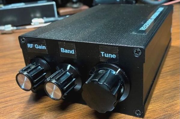
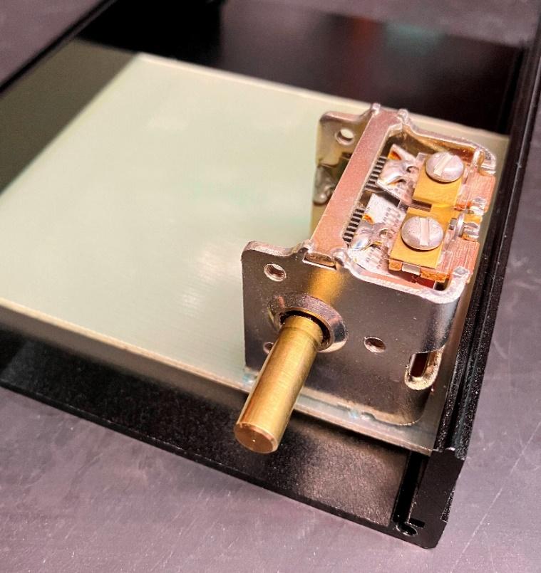
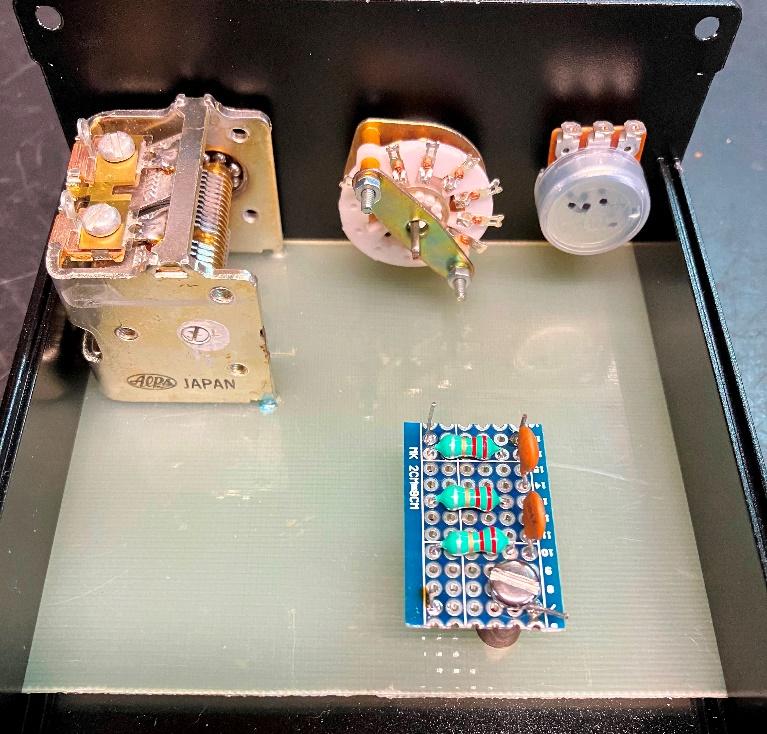
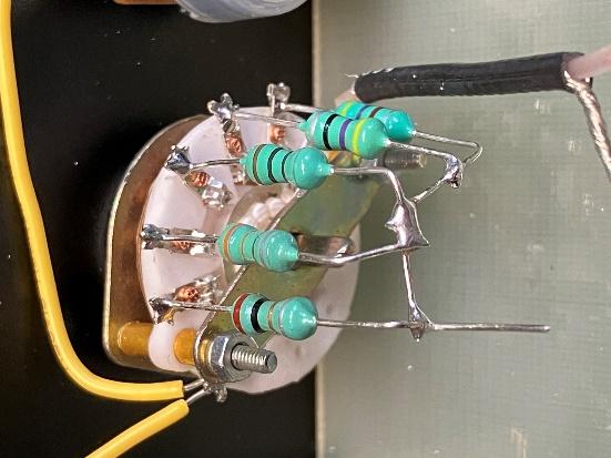
I stumbled upon a video by ElectroBananas on Youtube where he lays out, in exacting detail, how to create a hybrid of the ATS-20+ and the si4732 mini radio. The wiring isn’t difficult, and he even provides the design for a new front panel to 3D print.
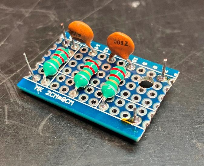
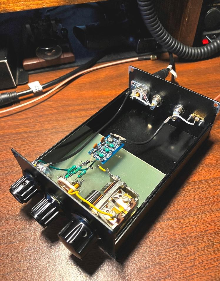
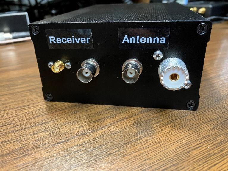
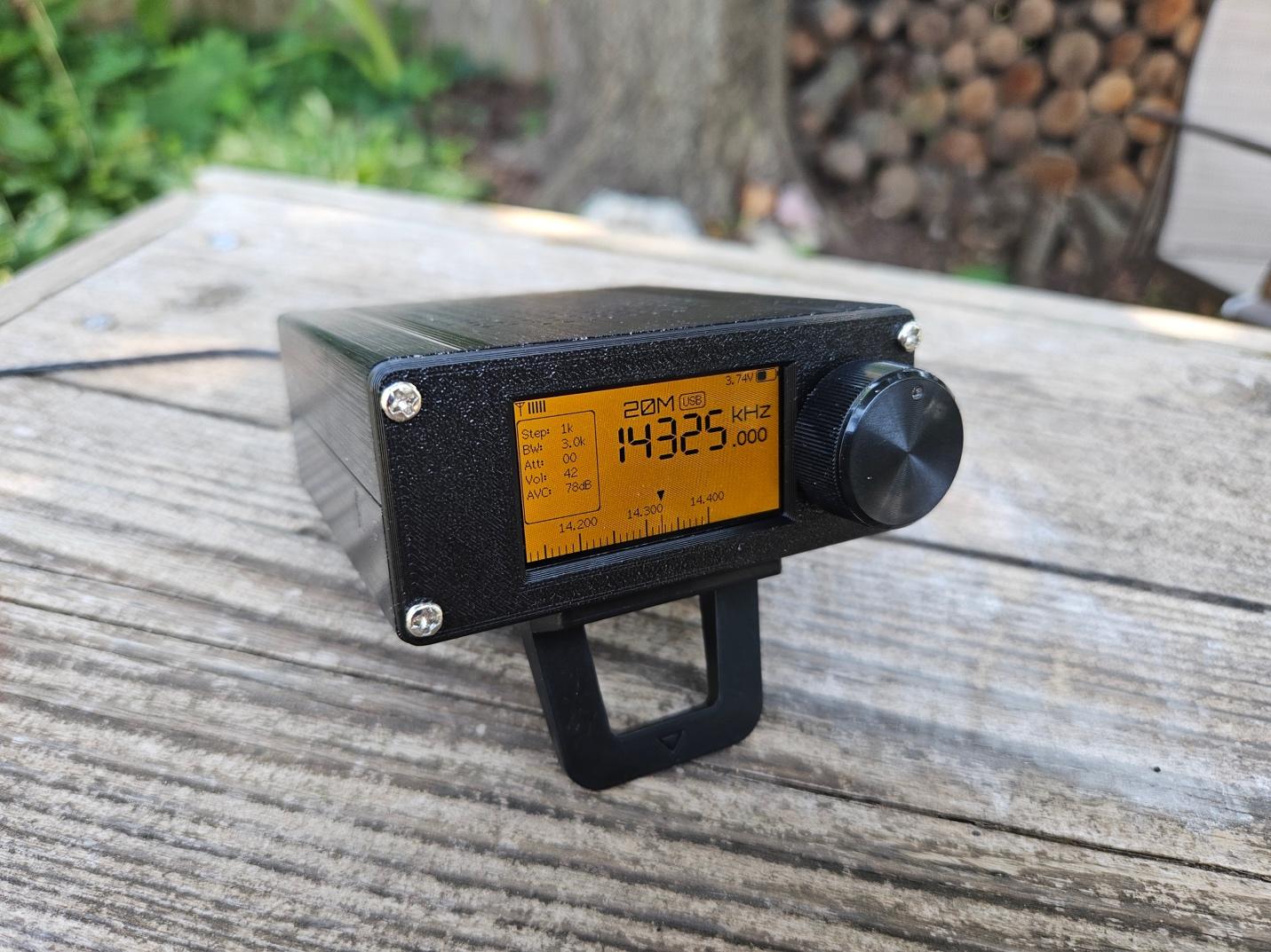
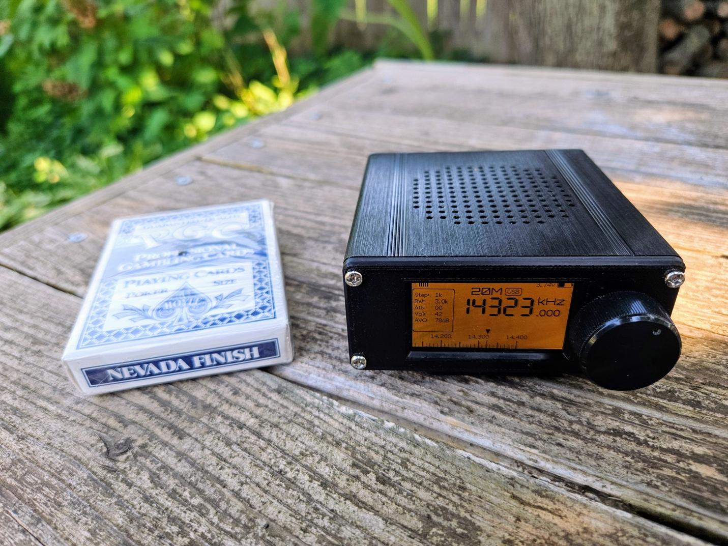
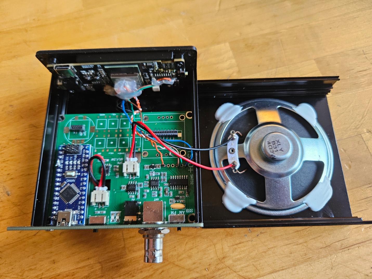 The advantage of combining these radios is that I have the better-designed RF front end of the ATS-20+, the powerful ESP32 microcontroller and the beautiful display of the mini, and the big speaker/audio/battery of the ATS-20+. While I was in there I also added some protection diodes (two back-to-back 2N4148s) to the antenna input. What’s fun is that I added a “bail” using a single mini laptop stand [affiliate] and changed the display to an orange theme. It looks like a miniature version of my Icom IC-703 (and in A-B tests they’re not too far off). It’s the best of both worlds. And it’s still very small, a perfect bedside radio, or one to carry to the beach.
 The combination of cheap hardware with open-source software development is creating a very exciting time in radio, and I look forward to see what emerges in the months ahead.
 Until then, I wonder if I could fit a low-powered CW transmitter in the case…