Category Archives: Radios

Bill’s first DX contest using a Panasonic RF-2200 and a hombrew diode/loop radio

Many thanks to SWLing Post contributor, Bill Hemphill (WD9EQD), who shares the following guest post:


My First DX Contest

by Bill Hemphill, WD9EQD

Being a recent new member of NJARC, this is my first time competing in this contest.  I have always been a big fan of BCB DXing and have recently got back into it – especially with the amateur radio bands being in such poor conditions.  The acquisition of a couple of Loop antennas plus two Panasonic RF-2200 radios have just enhanced my enjoyment.

For the contest, I used two completely different radios.  First was the RF-2200 and second was a spur of the moment creation.

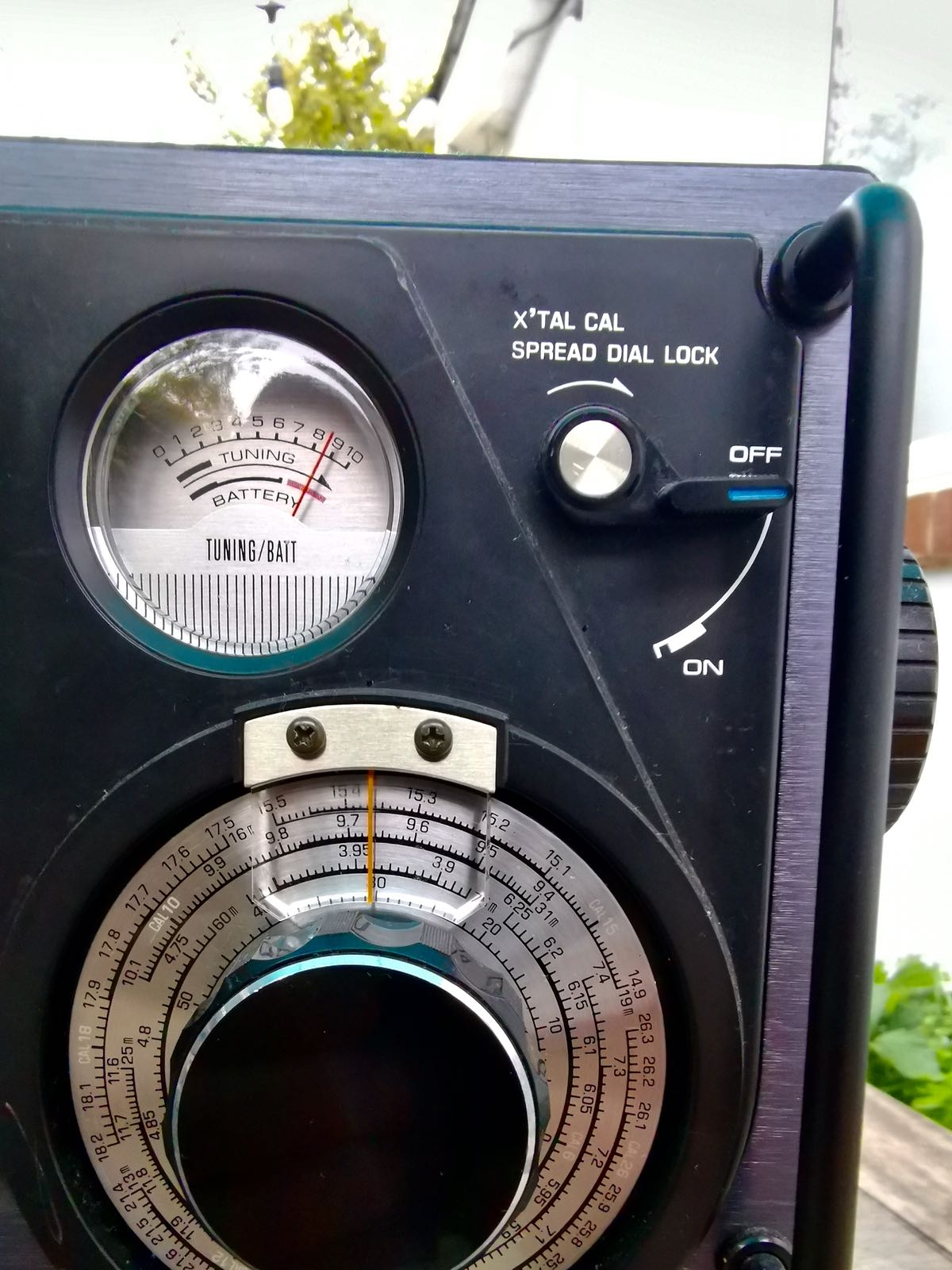
The RF-2200 was its usual good performer. While the RF-2200 has a beautiful built-in rotating bar antenna, I enhanced it with the 27” Torus-Tuner Loop Antenna as made by K3FDY, Edmund Wawzinski.  I think I had picked this antenna up at one of NJARC’s swap meets.  So I wish to thank whoever it was that was nice enough to bring it and sell it at the meet.  I have really enjoyed using it.  With this setup, I was hoping that I might be able to pull in Denver, Salt Lake City and maybe even a Mexican station, but it was a complete bust on them.  But I did have a nice surprise in receiving the Cuban station Radio Enciclopedia on 530 in addition to the usual Radio Reloj time signal station.  Following is photo of it in operation:

Originally, I had thought that my second contest entry would be done with a 1962 Sony TR-910T three-band transistor radio.  This radio has a fairly wide dial along with a second fine-tuning knob which would be a big help.  I would have again used the 27” hula-hoop antenna.

But I made the nice mistake of running across Dave Schmarder’s Makearadio website:

http://makearadio.com/

Dave’s site is a wonderful resource for creating your own Crystal, Tube, and Solid State radios as well as Audio Amplifiers and Loop Antennas.  While going down the rabbit hole of his site, I ran across his Loop Crystal Set, #19 Crystal Radio:

http://makearadio.com/crystal/19.php

What grabbed my attention was the wood frame loop antenna which is similar to one I had acquired a couple of years ago at a ham fest:


It was a really nicely constructed, nice swivel base.

I replaced the tuning capacitor with one that has a 6:1 ratio.

At this point I started thinking that I could create something similar with my loop.

I randomly grabbed a diode from my parts box.  Not sure what the exact model is.  (I later found out that it was an IN-34 which is what I was hoping it was.)  Then quickly soldered the diode, a resistor and capacitor to a RCA plug:

I then proceeded to use some jumper cables and just clip it to the tuning capacitor on the antenna base:

The RCA plug was then the audio out (I hope) from the radio.

I quickly realized that I did not have a crystal headset or any headset that would reproduce any audio.  So I used an old Marantz cassette recorder to act as an amplifier.  Fed it into the mic jack and then tried to listen to the monitor out.  Bingo – I could pick up or local station on 1340 really weak.

So I then fed the audio from the Marantz into a Edirol digital recorder.  Now I was getting enough audio for the headphones plus could make  a recording of the audio.

At last I was receiving some signals.  To boost the audio some more I removed the resistor from the circuit.

I found out the I could only tune from about 530 to 1350.  I probably needed to clip the lead on one of the loop turns, but I really wanted to see how it would do at night.  I spent several hours and was just totally amazed at how well it performed and how good the audio was.  The hardest part was when there were very strong signals on the adjacent frequency.  What I found really interesting was that it was not linear in its tuning.  At the low end of the band the stations were more spread out than at the higher end.  This made tuning fairy easy at the low end and very touchy at the high end.  I was able to hear a couple of Chicago stations along with Atlanta and St. Louis.

Here’s photo of it in action:

I have created an audio file of the station ID’s heard with the diode/loop radio.  The audio file is on the Internet Archive at:

https://archive.org/details/bcbstationidsondioderadio

I had a lot of fun in the contest and especially enjoyed trying something really different with the diode/loop radio.  Now I have a whole year to try to think up something really creative for next year’s contest.


Absolutely brilliant, Bill! I’m so happy to see that your ham fest homebrew loop has served you so very well in a contest. I love how you pulled audio from your homebrew, make-shift diode radio as well–using your audio gear in a chain for amplification obviously worked very well.

Thanks so much for sharing your experience, Bill!

Spread the radio love

Radio history videos are a serious benefit of Social Distancing!

Many thanks to SWLing Post contributor, Bill Hemphill (WD9EQD), who shares the following guest post:


Benefits to Social Distancing

I have discovered that there is a positive side effect of social distancing.  With so many organizations using Zoom and other video methods for their meeting, the volume of great videos to watch has drastically increased, with most of it residing on YouTube.  Also everyone is sharing video links that they have found with other.

For example, the New Jersey Antique Radio Club (NJARC) has, for some time, posted their monthly meetings on their YouTube channel.  They have very enjoyable presentations.  Last night was their virtual monthly meeting for June and they had a great talk by Prof. Joe Jesson on “What You Did Not Know About the RCA AR88.”

I am a fairly new member to NJARC and must recommend them to others.  They are a very active group and are currently having Zoom conferences weekly between the members.  They also host the RADIO TECHNOLOGY MUSEUM at the InfoAge Technology Center.

Link to NJARC:

http://www.njarc.org/

Link to NJARC YouTube channel:

https://www.youtube.com/user/njarc/

Link to the Radio Technology Museum:

http://www.rtm.ar88.net/

Last week, I received an email from Mark  Erdle (AE2EA) referring to some videos by the Antique Wireless Museum which is hosted by the Antique Wireless Association (AWA).  From his email:

The Radios (and Filming) of “Across the Pacific”  presented by AWA member Brian Harrison.  Brian served as the radio consultant for the 3-hour PBS documentary “Across the Pacific”, which tells the story of the early days of Pan American Airways and of Hugo C. Leuteritz, a RCA radio engineer who helped make Pan Am’s expansion across the oceans possible with radio communication and navigation systems. Brian explains how he worked to insure that this documentary portrayed the pioneering work of Hugo Leuteritz as accurately as possible. Much of the early radio equipment that Pan American used was custom made for Pan Am, and is quite rare today, but Brian hunted it down.


In addition to Brian’s video, you can also see Tom Perera’s updated presentation of “Phil Weingarten’s Fabulous Fakes” which was originally presented at the 2007 AWA conference:

Link to AWA:  https://antiquewireless.org/homepage/

Link to AWA You-Tube Channel:  https://www.youtube.com/channel/UCX55peBhzeX1qps_VYXdLBA

Here are some other videos that people have passed along to me that I have found enjoyable.  Most of these are radio-oriented and I have omitted the many cat videos:


Thank you for sharing these links and videos, Bill! I’ve been watching Phil Weingarten’s Fabulous Fakes this morning–what a fascinating bit of history!

Post readers: Have you discovered videos and sites while social distancing (a.k.a. Social DXing)? Please comment and share your links!

Spread the radio love

The AirSpy HF+ Discovery and a new era of portable SDR DXing

The following article first appeared in the January 2020 issue of The Spectrum Monitor magazine.


The AirSpy HF+ Discovery and a new era of portable DXing

I admit it: I used to be a bit of an old-fashioned radio curmudgeon. One of those, “I like my radios with knobs and buttons” likely followed by, “…and no other way!”

However, about fifteen years ago, many of my DXing friends started turning to the world of software defined radios (or in common parlance, “SDRs”). I staunchly opposed ever following in their footsteps. One of the reasons I for this––a good one––is that, since I spend the bulk of my day in front of a computer, why would I ever want to use a computer when I’m playing radio?

But then…gradually, I found myself playing around with a few SDRs. And I quickly learned that third-generation SDRs were capable of doing something very impressive (and fun), indeed:  making spectrum recordings.  Using this tool, I found I could record not only the audio of one individual signal, but the audio of entire swathes of radio spectrum.  And even more impressive, I learned that you could later load or “play back” the spectrum recording and tune through the bands as if in real time. Any time you want. Before long, I was hooked: SDRs had become my portal into radio time travel!

I quickly found that I loved many of the other advantages of using an SDR, as well, including visual ones––like the ability to view spectrum. The interactive interface allows one to actually see radio signals across the band in real time. I also found incredible value in waterfall displays, which show signals changing in amplitude and frequency over time. Cool stuff.

I purchased my first dedicated SDR in 2012, a WinRadio Excalibur. It was––and still is––a benchmark receiver, performing circles around my tabletop receivers and general coverage transceivers.

And today, although I own and love a number of legacy radios and still listen to them in the good old-fashioned manner to which I became accustomed, I find I’m now spending the bulk of my time DXing with SDRs.

And then, more recently, two amazing things happened in the world of SDRs. Strong market competition, together with serious innovations, have come into play. Thus, for less than $200 US, you can now purchase an SDR that would have easily cost $1,000 US only ten years ago. And now, in many cases, the $200 SDR of today will outperform the $1,000 SDR of yesteryear. We are, indeed, living in good times.

And now––no more a radio curmudgeon––I’m comfortable with my SDR-user status and time at the computer, and glad I was just curious enough about SDRs to let them into my radio (and computer) world.

Portable SDRs

Since I initially dived into the world of SDRs, I’ve tried to think of a way to take them into the field.

But first, let’s get an obvious question out of the way:

Why would you want to drag an SDR into the field, when a traditional battery-powered radio is so much easier to manage?

After all, you may say, portable and even mobile tabletop receivers require no computer, no hard drive, and are likely more reliable because there are less components to manage or to cause problems for you.

In answer, let’s look at a few scenarios where heading to the field with an SDR system might just make sense.  (Hint: Many of these reasons are rooted in the SDR’s ability to record spectrum).

Good Reason #1:  Your home location is not ideal for playing radio.

Photo by Henry Be

My good friend, London Shortwave, lives in the middle of London, England. He’s an avid radio enthusiast and DXer, but his apartment is almost a perfect storm of radio interference. Listening from his home is challenging, to say the least: he can only use indoor antennas and RFI/QRM simply inundated his local airwaves.

Many years ago, he discovered that the best way to DX was to go to an area that put urban noise and radio interference at a distance.  He found that by visiting large local parks, he could play radio with almost no RFI.

Being a computer guru, he started working on a portable SDR setup so that he could go to a park, set up an antenna, and record radio spectrum while he read a book.  His systems evolved with time, each iteration being more compact less conspicuous that the previous. Later, he could head back home, open the recorded spectrum files, and tune through these “time-shifted” recordings in the comfort of his flat. This allowed London Shortwave to maximize the low-RFI listening experience by reliving the time in the park.

Over the years, he tweaked and adapted his setup, often writing his own code to make small tablets and portable computers purpose-built portable-spectrum-capture devices. If you’re curious, you might like to read about the evolution of his systems on his blog.

Clearly, for London Shortwave, an SDR is the right way to capture spectrum and thus likely the best solution for his DX listening.

Good Reason #2:  Weak-signal workarounds.

Typically radio enthusiasts turn to field operation to work in a lower-noise environment and/or where there are no antenna restrictions, often to log new stations and DX.

SDRs afford the DXer top-shelf tools for digging weak signals out of the muck. SDR applications have advanced tools for tweaking AGC settings, synchronous detectors, filters, noise reduction, and even to tailor audio.

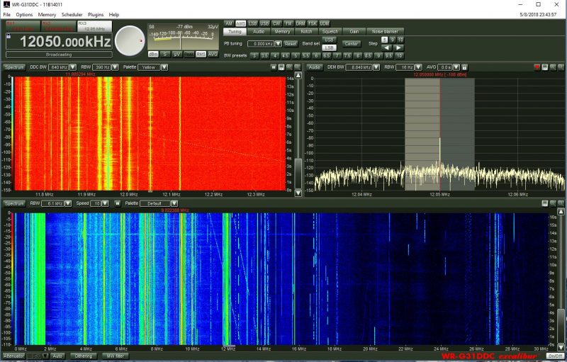
The WinRadio Excalibur application even includes a waterfall display which represents the entire HF band (selectable 30 MHz or 50 MHz in width)

On top of that, being able to see a swath of spectrum and waterfall gives one an easier way––a visual way––to pinpoint weak or intermittent signals. This is much harder to do with a legacy radio.

Case in point:  I like listening to pirate radio stations on shortwave. With a spectrum display, I can see when a new station may be tuning up on the band so can position the receiver to listen in from the beginning of the broadcast, and never miss a beat.

Or, in another example, the visual aspect of spectrum display means I can easily locate trans-Atlantic DX on the mediumwave bands by looking for carrier peaks on the spectrum display outside the standard North American 10 kHz spacing. The signals are very easy to spot.

Good Reason #3: DXpeditions both small and large.

Mark Fahey, scanning the bands with his WinRadio Excalibur/Surface Pro 2 combo at our 2015 PARI DXpedition

Whether you’re joining an organized DXpedition or you’re simply enjoying a little vacation DXpedition, SDRs allow you to make the most of your radio time.

Indeed, most of the organized DXpedition these days heavily incorporate the use of SDRs specifically so DXers can record spectrum. Much like example #1 above, doing this allows you to enjoy the noise-free optimal conditions over and over again through spectrum recordings. Most DXpeditioners will have an SDR making recordings while they use another receiver to DX in real time. Later, they take the recording home and dig even more weak signals out of the mix: ones that might have otherwise gone unnoticed.

Good Reason #4: Sharing the spectrum with like-minded listeners.

Earlier this year, Mark gave me this 8TB hard drive chock-full of spectrum recordings.

One of the joys I’ve discovered  in making field spectrum recordings is sharing them with fellow DXers. Most of the time when I go to shortwave radio gatherings (like the Winter SWL Fest), I take a couple hard drives to exchange with other SDR enthusiasts. My friend, Mark Fahey, and I have exchanged some of our favorite spectrum recordings this way. I give him a hard drive chock-full of terabytes of recordings, and he reciprocates. Back home (or on the train or airplane) I open one of his recordings and, boom! there I am in his shack in Freeman’s Reach, Australia, tuning through Pacific stations that are not easily heard here in North America, maybe even turning up some gems Mark himself may have overlooked…just as he is doing with my recordings from the southeast US.

I’ve also acquired DXpedition spectrum recordings this way. It’s great fun to “be there” through the recordings and to enjoy some of the benefits of being on the DXpedition in times when I couldn’t actually make it there in person. For a DXer with a consuming job, busy family life, or maybe health problems that limit their travel, an SDR recording is the way to go.

Good Reason #5: Family time

Photo by David Straight

I’m a husband and father, and no matter how much I like to play radio when we’re on vacation, my family comes first, and our family activities take priority.

Having a field-portable SDR setup means that I can arrange a “set it and forget it” spectrum capture device. Before we head out the door for a family visit, tour of the area, or a hike, I simply set my SDR to record spectrum, then listen to what I “caught” after I return, or after I’m home from vacation.

This practice has allowed me to enjoy radio as much as I like, without interrupting our family adventures. Can’t beat it!

Past challenges

With all of these benefits, one might wonder why many other DXers  haven’t been using portable SDRs in the field for a while now? That’s a good question.

Power

The WinRadio G31DDC, like many SDRs of the era, has separate data and power ports

In prior years, DXers and listeners might have been reluctant to lug an SDR and its requisite apparatus out with them. After all, it’s only been in the past decade or so that SDRs haven’t required a separate custom power supply; some legacy SDRs either required an odd voltage, or as with my WinRadio Excalibur, have very tight voltage tolerances.

Originally, taking an SDR to the field––especially in places without grid mains power––usually meant you also had to take a pricey pure sine wave inverter as well as a battery with enough capacity to run the SDR for hours on end.

Having spent many months in an off-grid cabin on the east coast of Prince Edward Island, Canada, I can confidently say it’s an ideal spot for DXing: I can erect large wire antennas there, it’s on salt water, and there are literally no locally-generated man-man noises to spoil my fun.  Of course, anytime we go to the cottage, I record spectrum, too, as this is truly a honey of a listening spot.

The view from our off-grid cabin on PEI.

The first year I took an SDR to the cabin, I made a newbie mistake:  it never dawned on me until I arrived and began to put it to use that my Goal Zero portable battery pack didn’t have a pure sine wave inverter; rather, I found it had a modified sine wave inverter built into it. The inverter could easily power my SDR, sure, but it also injected incredibly strong, unavoidable broadband noise into the mix. It rendered my whole setup absolutely useless. I gave up on the SDR on that trip.

Both the Airspy HF+ (top) and FDM-S2 (bottom) use a USB connection for both data transfer and power. Photo by Guy Atkins.

Today, most SDRs actually derive their power from a computer or laptop through a USB cable, one that doubles as a data and power cable. This effectively eliminates the need for a separate power system and inverter.

Of course, your laptop or tablet will need a means of recharging in the field because the attached SDR will drain its battery a little faster. Nowadays it’s possible to find any number of portable power packs/banks and/or DC battery sources to power laptops or tablets, as long as one is cautious that the system doesn’t inject noise. This still requires a little trial and error, but it’s much easier to remedy than having two separate power sources.

Portable computers

Even a Raspberry Pi 3B has enough horsepower to run SDR applications.

An SDR is nothing without a software application to run it. These applications, of course, require some type of computer.

I the past, SDR applications needed some computing horsepower, not necessarily to run the application itself, but to make spectrum recordings.  In addition, they often required extra on-board storage space to make these recordings sufficiently long to be useful.  This almost always meant lugging a full-sized laptop to the field, or else investing in a very pricey tablet with a hefty amount of internal storage to take along.

Today we’re fortunate to have a number of more portable computing devices to run SDR applications in the field: not just laptops or tablets, but mobile phones and even mini computers, like the eminently affordable $46 Raspberry Pi. While you still have to be conscious of your device’s computing horsepower, many small devices are amply equipped to do the job.

Storage

64-128 GB USB flash/thumb drives are affordable, portable storage options.

If you’re making spectrum and audio recordings in the field, you’ll need to store them somehow. Wideband spectrum recordings can use upwards of 2GB of data per minute or two.

Fortunately, even a 64GB USB flash drive can be purchased for as little as $7-10 US. This makes for quick off-loading of spectrum recordings from a device’s internal memory.

My portable SDR setup

It wasn’t until this year that all of the pieces finally came together for me so that I could enjoy a capable (and affordable!) field-portable SDR setup. Two components, in particular, made my setup a reality overnight; here’s what made the difference.

The AirSpy HF+ Discovery

Last year, AirSpy sent me a sample of their new HF+ Discovery SDR to test and evaluate. To be fully transparent, this was at no cost to me.

I set about putting the HF+ Discovery through its paces. Very soon, I reached a conclusion:  the HF+ Discovery is simply one of the best mediumwave and HF SDRs I’ve ever tested. Certainly, it’s the new benchmark for sub-$500 SDRs.

In fact, I was blown away. The diminutive HF+ Discovery even gives some of my other benchmark SDRs a proper run for their money. Performance is DX-grade and uncompromising, sporting impressive dynamic range and superb sensitivity and selectivity. The noise floor is also incredibly low. And I still can’t wrap my mind around the fact that you can purchase this SDR for just $169 US.

The HF+ Discovery compared in size to a DVD

In terms of portability, it’s in a class of its own. It’s tiny and incredibly lightweight. I evaluate and review SDRs all the time, but I’ve never known one that offers this performance in such a tiny package.

Are there any downsides to the HF+ Discovery? The only one I see––and it’s intentional––is that it has a smaller working bandwidth than many other similar SDRs at 768 kHz (although only recently, Airspy announced a firmware update that will increase bandwidth). Keep in mind, however, that the HF+ series SDRs were designed to prevent overload when in the presence of strong local signals. In fairness, that’s a compromise I’ll happily make.

Indeed, the HF+ Discovery maximum bandwidth isn’t a negative in my estimation unless I’m trying to grab the entire mediumwave band, all at once. For shortwave work, it’s fine because it can typically cover an entire broadcast band, allowing me to make useful spectrum recordings.

The HF+ Discovery is so remarkably tiny, that this little SDR, together with a passive loop antenna, can fit in one small travel pouch. Ideal.

The antennas

My homebrew NCPL antenna

Speaking of antennas, one of the primary reasons I’m evaluating the HF+ Discovery is because it has a very high dynamic range and can take advantage of simple antennas, in the form of passive wideband magnetic loop antennas, to achieve serious DX.

AirSpy president and engineer, Youssef Touil, experimented with several passive loop antenna designs and sizes until he found a few combinations ideally matched with the HF+ Discovery.

My good buddy, Vlado (N3CZ) helped me build such an antenna per Youssef’s specifications. Vlado had a length of Wireman Flexi 4XL that was ideal for this project (thanks, Vlad!). The only tricky part was penetrating the shielding and dielectric core at the bottom of the loop, then tapping into both sides of the center conductor for the balun connections.  Being Vlado, he used several lengths of heat shrink tubing to make a nice, clean, snag-free design. I’ll freely admit that, had I constructed this on my own, it wouldn’t have been nearly as elegant!

Click here for a step-by-step guide to building your own NCPL (Noise-Cancelling Passive Loop Antenna.

Youssef also sent me a (then) prototype Youloop passive loop antenna. It’s incredibly compact, made of high quality SMA-fitted coaxial cables. It can be set up in about 30 seconds and coiled to tuck into a jacket pocket.  The AirSpy-built loop has a lower loss transformer than the one in the homemade loop, which translates into a lower noise figure for the system.

Click here to read my review of the Youloop.

Let’s face it: SDR kit simply doesn’t get more portable than this.

The computer

My Microsoft Surface Go tablet on a hotel bed.

In the past, I used an inexpensive, circa 2013 mini Windows laptop with an internal SSD drive.  Everything worked beautifully, save the fact that it was challenging to power in the field and the internal capacity of the hard drive was so small (16GB less the operating system). In addition, it was a few years old, bought used, so the processor speed was quite slow.

This year, on the way back from the Huntsville Hamfest, I stopped by the Unclaimed Baggage Center in Scottsboro, Alabama. This center has a wide variety of used portable electronics at discount prices. I felt pretty lucky when I discovered a like-new condition Microsoft Surface Go tablet and keyboard with original charger for $190. The catch? The only data port on the tablet is a USB-C. But I grabbed a small USB-C to standard USB 3.0 dongle (for $2!) and took a risk that it would work with the HF+ Discovery.

Fortunately, it did! Score!

While the Surface Go is no powerhouse, it’s fast enough to run any of my SDRs and make spectrum recordings up to 2 MHz in width without stuttering. The only noise it seems to inject into the mix is a little RFI when I touch the trackpad on the attached keyboard.

Power

One of my LiFePo batteries

The HF+ Discovery draws power from the Surface Go tablet via the USB port. With no additional power supply, the Surface Go may only power the HF+ Discovery for perhaps an hour at most. Since I like doing fully off-grid operations and needed to avoid RFI from inverters, I needed a portable power solution.

Fortunately, the Surface Go has a dedicated power port, so I immediately ordered a DC power cable with a standard car lighter plug.

At the Huntsville Hamfest I also purchased a small 12V 4.5 Ah Bioenno LiFePo battery and paired it with a compact Powerpole distribution panel kit I purchased in May at the 2019 Dayton Hamvention.

The LiFePo battery is small, lightweight, and can power the tablet /SDR combo for hours on end. Moreover, I have noticed no extra noise injected when the DC power is applied.

My HF+ Discovery-based portable SDR kit

My portable SDR kit on a hotel balcony.

Now I have this kit, I couldn’t be more pleased with it. When all of the components of my SDR system are assembled, they work harmoniously. The entire ensemble is also incredibly compact:  the loop antennas, SDR, Surface Go tablet, battery, and distribution panel all fit in a very small travel pack, perfect for the grab-and-go DX adventure.

The entire kit: SDR, cables, Youloop antenna, connectors and adapters all fit in my Red Oxx Lil’ Roy pack.

In November, I took the kit to the coast of South Carolina and had a blast doing a little mediumwave DXing from our hotel balcony. We were very fortunate in that I had two excellent spots to hang the homemade loop antenna: on the main balcony, and from the mini balcony off the master bedroom. Both spots yielded excellent results.

What impressed me most was the fact that the SDR# spectrum display and waterfall were absolutely chock-full of signals, and there was very little noise, even in the popular resort area where we were staying. I found that my portable radios struggled with some of the RFI emanating from the hotel, but the HF+ Discovery and passive loop combo did a much better job mitigating noise.

Check out the AM broadcast band on the spectrum display.

But no need to take my word for it.  If you would like to experience it first hand, why not download an actual spectrum recording I made using this setup?

All you’ll need to do is:

  1. Download the 1.7 GB (.wav formatted) spectrum file at this address
  2. Download a copy of SDR# if you don’t already have an SDR application that can read AirSpy spectrum files.
  3. Install SDR#, and run it.
  4. At the top left corner of the SDR# screen, choose “IQ File (.wav)” as the source, then point it to where you downloaded the file.
  5. Press the play button, and experience a little radio time travel!

This particular recording was made on the mediumwave band on November 17, 2019, starting at around 01:55 UTC.

My portable SDR kit capturing spectrum during a hike in Pisgah National Forest.

I’ve also taken this setup to several parks and remote outdoor locations, and truly enjoyed the freedom of taking spectrum recordings back home to dig through the signals.

Conclusion

I finally have a portable SDR system that allows me the flexibility to make spectrum recordings while travelling. The whole setup is compact and can easily be taken in a carry-on bag when flying.

The glory of this is, I can tune through my spectrum recordings in real time and DX when I’m back home, or even on the way back home, in the car, train, or airplane. It’s simply brilliant.

If you don’t already own an SDR, I can highly recommend the AirSpy HF+ Discovery if you’re primarily interested in HF and MW DXing. If you need a wideband SDR, I could also recommend the recently released SDRplay RSPdx, although it’s slightly heavier and larger than the AirSpy.

Thankfully, I am now an SDR enthusiast that can operate in the field, and this radio has had a lot to do with it. I’ll be logging many hours and miles with the AirSpy HF+ Discovery: its incredibly compact footprint, combined with its brilliant performance, is truly a winning combo.

Click here to check out the Airspy HF+ Discovery

Related articles:


Do you enjoy the SWLing Post?

Please consider supporting us via Patreon or our Coffee Fund!

Your support makes articles like this one possible. Thank you!

Spread the radio love

“Letters of a Radio-Engineer to His Son”

Many thanks to SWLing Post contributor, Paul, who shares a link to Letters of a Radio-Engineer to his Son by John Mills. The book, originally published in 1922, is in the public domain and shared/hosted on the Project Gutenberg website.

It is a fascinating read. Mills does a rather amazing job explaining complex electronic principles in a simple narrative form.

To give you a taste, check out Letter 3 – How a Battery Works below:


LETTER 3
HOW A BATTERY WORKS

(This letter may be omitted on the first reading.)

My Dear Boy:

When I was a boy we used to make our own batteries for our experiments. That was before storage batteries became as widely used as they are to-day when everybody has one in the starting system of his automobile. That was also before the day of the small dry battery such as we use in pocket flash lights. The batteries which we made were like those which they used on telegraph systems, and were sometimes called “gravity” batteries. Of course, we tried several kinds and I believe I got quite a little acid around the house at one time or another. I’ll tell you about only one kind but I shall use the words “electron,” “proton,” “nucleus,” “atom,” and “molecule,” about some of which nothing was known when I was a boy.

We used a straight-sided glass jar which would hold about a gallon. On the bottom we set a star shaped arrangement made of sheets of copper with a long wire soldered to it so as to reach up out of the jar. Then we poured in a solution of copper sulphate until the jar was about half full. This solution was made by dissolving in water crystals of “blue vitriol” which we bought at the drug store.

17Blue vitriol, or copper sulphate as the chemists would call it, is a substance which forms glassy blue crystals. Its molecules are formed of copper atoms, sulphur atoms, and oxygen atoms. In each molecule of it there is one atom of copper, one of sulphur and four of oxygen.

When it dissolves in water the molecules of the blue vitriol go wandering out into the spaces between the water molecules. But that isn’t all that happens or the most important thing for one who is interested in making a battery.

Each molecule is formed by six atoms, that is by six little groups of electrons playing about six little nuclei. About each nucleus there is going on a game but some of the electrons are playing in the game about their own nucleus and at the same time taking some part in the game which is going on around one of the other nuclei. That’s why the groups or atoms stay together as a molecule. When the molecules wander out into the spaces between the water molecules something happens to this complicated game.

It will be easiest to see what sort of thing happens if we talk about a molecule of ordinary table salt, for that has only two atoms in it. One atom is sodium and one is chlorine. The sodium molecule has eleven electrons playing around its nucleus. Fairly close to the nucleus there are two electrons. Then farther away there are eight more and these are having a perfect game. Then still farther away from the nucleus there is a single lonely electron.

The atom of chlorine has seventeen electrons which 18play about its nucleus. Close to the nucleus there are two. A little farther away there are eight just as there are in the sodium atom. Then still farther away there are seven.

I am going to draw a picture (Fig. 1) to show what I mean, but you must remember that these electrons are not all in the same plane as if they lay on a sheet of paper, but are scattered all around just as they would be if they were specks on a ball.

You see that the sodium atom has one lonely electron which hasn’t any play fellows and that the chlorine atom has seven in its outside circle. It appears that eight would make a much better game. Suppose that extra electron in the sodium atom goes over and plays with those in the chlorine atom so as to make eight in the outside group as I have shown Fig. 2. That will be all right as long as it doesn’t get out of sight of its own nucleus because you remember that the sodium nucleus is responsible for eleven electrons. The lonely electron of the sodium atom needn’t be lonely any more if it can persuade its nucleus to stay so close to the chlorine atom that it can play in the outer circle of the chlorine atom.

The outer circle of the chlorine atom will then have a better game, for it will have just the eight that makes a perfect game. This can happen if the chlorine atom will stay close enough to the sodium atom so that the outermost electron of the sodium atom can play in the chlorine circle. You see everything will be satisfactory if an electron can be shared by the two atoms. That can happen only if the two atoms stay together; that is, if they form a molecule. That’s why there are molecules and that’s what I meant when I spoke of the molecule as a big game played by the electrons of two or more atoms.

This molecule which is formed by a sodium atom and a chlorine atom is called a molecule of sodium chloride by chemists and a molecule of salt by most every one who eats it. Something strange happens when it dissolves. It wanders around between the water molecules and for some reason or other–we don’t know exactly why–it decides to split up again into sodium and chlorine but it can’t quite do it. The electron which joined the game about the chlorine nucleus won’t leave it. The result is that the nucleus of the sodium atom gets away but it leaves this one electron behind.

What gets away isn’t a sodium atom for it has one too few electrons; and what remains behind isn’t a chlorine atom for it has one too many electrons. We call these new groups “ions” from a Greek word which means “to go” for they do go, wandering off into the spaces between the water 20molecules. Fig. 3 gives you an idea of what happens.

You remember that in an atom there are always just as many protons as electrons. In this sodium ion which is formed when the nucleus of the sodium atom breaks away but leaves behind one planetary electron, there is then one more proton than there are electrons. Because it has an extra proton, which hasn’t any electron to associate with, we call it a plus ion or a “positive ion.” Similarly we call the chlorine ion, which has one less proton than it has electrons, a minus or “negative ion.”

Now, despite the fact that these ions broke away from each other they aren’t really satisfied. Any time that the sodium ion can find an electron to take the place of the one it lost it will welcome it. That is, the sodium ion will want to go toward places where there are extra electrons. In the same way the chlorine ion will go toward places where electrons are wanted as if it could satisfy its guilty conscience by giving up the electron which it stole from the sodium atom, or at least by giving away some other electron, for they are all alike anyway.

Sometimes a positive sodium ion and a negative chlorine ion meet in their wanderings in the solution and both get satisfied by forming a molecule 21again. Even so they don’t stay together long before they split apart and start wandering again. That’s what goes on over and over again, millions of times, when you dissolve a little salt in a glass of water.

Now we can see what happens when copper sulphate dissolves. The copper atom has twenty-nine electrons about its nucleus and all except two of these are nicely grouped for playing their games about the nucleus. Two of the electrons are rather out of the game, and are unsatisfied. They play with the electrons of the part of the molecule which is called “sulphate,” that is, the part formed by the sulphur atom and the four oxygen atoms. These five atoms of the sulphate part stay together very well and so we treat them as a group.

The sulphate group and the copper atom stay together as long as they are not in solution but when they are, they act very much like the sodium and chlorine which I just described. The molecule splits up into two ions, one positive and one negative. The positive ion is the copper part except that two of the electrons which really belong to a copper atom got left behind because the sulphate part wouldn’t give them up. The rest of the molecule is the negative ion.

The copper ion is a copper atom which has lost two electrons. The sulphate ion is a combination of one sulphur atom, four oxygen atoms and two electrons which it stole from the copper atom. Just as the sodium ion is unsatisfied because in it there is one more proton than there are electrons, so the copper ion is unsatisfied. As a matter of fact it is twice 22as badly unsatisfied. It has two more protons than it has electrons. We say it has twice the “electrical charge” of the sodium ion.

Just like a sodium ion the copper ion will tend to go toward any place where there are extra electrons which it can get to satisfy its own needs. In much the same way the sulphate ion will go toward places where it can give up its two extra electrons. Sometimes, of course, as ions of these two kinds wander about between the water molecules, they meet and satisfy each other by forming a molecule of copper sulphate. But if they do they will split apart later on; that is, they will “dissociate” as we should say.

Now let’s go on with the kind of batteries I used to make as a boy. You can see that in the solution of copper sulphate at the bottom of the jar there was always present a lot of positive copper ions and of negative sulphate ions.

On top of this solution of copper sulphate I poured very carefully a weak solution of sulphuric acid. As I told you, an acid always has hydrogen in its molecules. Sulphuric acid has molecules formed by two hydrogen atoms and one of the groups which we decided to call sulphate. A better name for this acid would be hydrogen sulphate for that would imply that its molecule is the same as one of copper sulphate, except that the place of the copper is taken by two atoms of hydrogen. It takes two atoms of hydrogen because the copper atom has two lonely electrons while a hydrogen atom only has one. It takes two electrons to fill up the game which the 23electrons of the sulphate group are playing. If it can get these from a single atom, all right; but if it has to get one from each of two atoms, it will do it that way.

I remember when I mixed the sulphuric acid with water that I learned to pour the acid into the water and not the other way around. Spatterings of sulphuric acid are not good for hands or clothes. With this solution I filled the jar almost to the top and then hung over the edge a sort of a crow’s foot shape of cast zinc. The zinc reached down into the sulphuric acid solution. There was a binding post on it to which a wire could be connected. This wire and the one which came from the plate of copper at the bottom were the two terminals of the battery. We called the wire from the copper “positive” and the one from the zinc “negative.”

Now we shall see why and how the battery worked. The molecules of sulphuric acid dissociate in solution just as do those of copper sulphate. When sulphuric acid molecules split, the sulphate part goes away with two electrons which don’t belong to it and each of the hydrogen atoms goes away by itself but without its electron. We call each a “hydrogen ion” but you can see that each is a single proton.

In the two solutions are pieces of zinc and copper. Zinc is like all the rest of the metals in one way. Atoms of metals always have lonely electrons for which there doesn’t seem to be room in the game which is going on around their nuclei. Copper as we saw has two lonely electrons in each atom. Zinc 24also has two. Some metals have one and some two and some even more lonely electrons in each atom.

What happens then is this. The sulphate ions wandering around in the weak solution of sulphuric acid come along beside the zinc plate and beckon to its atoms. The sulphate ions had a great deal rather play the game called “zinc sulphate” than the game called “hydrogen sulphate.” So the zinc atoms leave their places to join with the sulphate ions. But wait a minute! The sulphate ions have two extra electrons which they kept from the hydrogen atoms. They don’t need the two lonely electrons which each zinc atom could bring and so the zinc atom leaves behind it these unnecessary electrons.

Every time a zinc atom leaves the plate it fails to take all its electrons with it. What leaves the zinc plate, therefore, to go into solution is really not a zinc atom but is a zinc ion; that is, it is the nucleus of a zinc atom and all except two of the planetary electrons.

Every time a zinc ion leaves the plate there are left behind two electrons. The plate doesn’t want them for all the rest of its atoms have just the same number of protons as of electrons. Where are they to go? We shall see in a minute.

Sometimes the zinc ions which have got into solution meet with sulphate ions and form zinc sulphate molecules. But if they do these molecules split up sooner or later into ions again. In the upper part of the liquid in the jar, therefore, there are sulphate 25ions which are negative and two kinds of positive ions, namely, the hydrogen ions and the zinc ions.

Before the zinc ions began to crowd in there were just enough hydrogen ions to go with the sulphate ions. As it is, the entrance of the zinc ions has increased the number of positive ions and now there are too many. Some of the positive ions, therefore, and particularly the hydrogen ions, because the sulphate prefers to associate with the zinc ions, can’t find enough playfellows and so go down in the jar.

Down in the bottom of the jar the hydrogen ions find more sulphate ions to play with, but that leaves the copper ions which used to play with these sulphate ions without any playmates. So the copper ions go still further down and join with the copper atoms of the copper plate. They haven’t much right to do so, for you remember that they haven’t their proper number of electrons. Each copper ion lacks two electrons of being a copper atom. Nevertheless they join the copper plate. The result is a plate of copper which has too few electrons. It needs two electrons for every copper ion which joins it.

How about the zinc plate? You remember that it has two electrons more than it needs for every zinc ion which has left it. If only the extra electrons on the negative zinc plate could get around to the positive copper plate. They can if we connect a wire from one plate to the other. Then the electrons from the zinc stream into the spaces between the atoms of the wire and push ahead of them the electrons 26which are wandering around in these spaces. At the other end an equal number of electrons leave the wire to satisfy the positive copper plate. So we have a stream of electrons in the wire, that is, a current of electricity and our battery is working.

That’s the sort of a battery I used to play with. If you understand it you can get the general idea of all batteries. Let me express it in general terms.

At the negative plate of a battery ions go into solution and electrons are left behind. At the other end of the battery positive ions are crowded out of solution and join the plate where they cause a scarcity of electrons; that is, make the plate positive. If a wire is connected between the two plates, electrons will stream through it from the negative plate to the positive; and this stream is a current of electricity.

Pl. III.–Dry Battery for Use in Audion Circuits (Courtesy of National Carbon Co., Inc.) Storage Battery (Courtesy of the Electric Storage Battery Co.).


Click here to read the entire book.

Spread the radio love

Just pulled the trigger on the new QCX+ CW/WSPR QRP transceiver kit

I’m a real sucker for kits of any stripe.

A few days ago, my buddy, Pete (WB9FLW), sent me a tip about the new QCX+ CW/WSPR transceiver by QRP Labs. I posted an announcement on QRPer.com.

I’ve yet to build a QRP Labs kit, but I’ve only heard positive reviews from readers and friends. QRP Labs’ president, Hans Summers (G0UPL), is an amazing kit designer and, indeed, won the 2019 Homebrew Heroes Award.

Hans kindly took a break so that I could snap his photo at Hamvention 2019.

Last year, at the 2019 Hamvention, QRP Labs had a table across from ours and, based on the amount of people huddled around his table all day long, I’m certain he was one of the busiest vendors at Hamvention.

His new QCX+ transceiver is an upgraded/updated version of the original QCX transceiver which has sold nearly 10,000 units. In the following video, Hans describes in detail how the QCX+ is designed and the differences between it and its predecessor:

Since I’ve quite a few things on my Social DX bucket list–including the recent addition of QRP EME (I mean, what am I thinking?)–and since I don’t really need yet another CW QRP transceiver, I required a good excuse to buy and build this kit. So I turned to my editor at RadCom who very much wanted review. Fantastic excuse! Thank you!
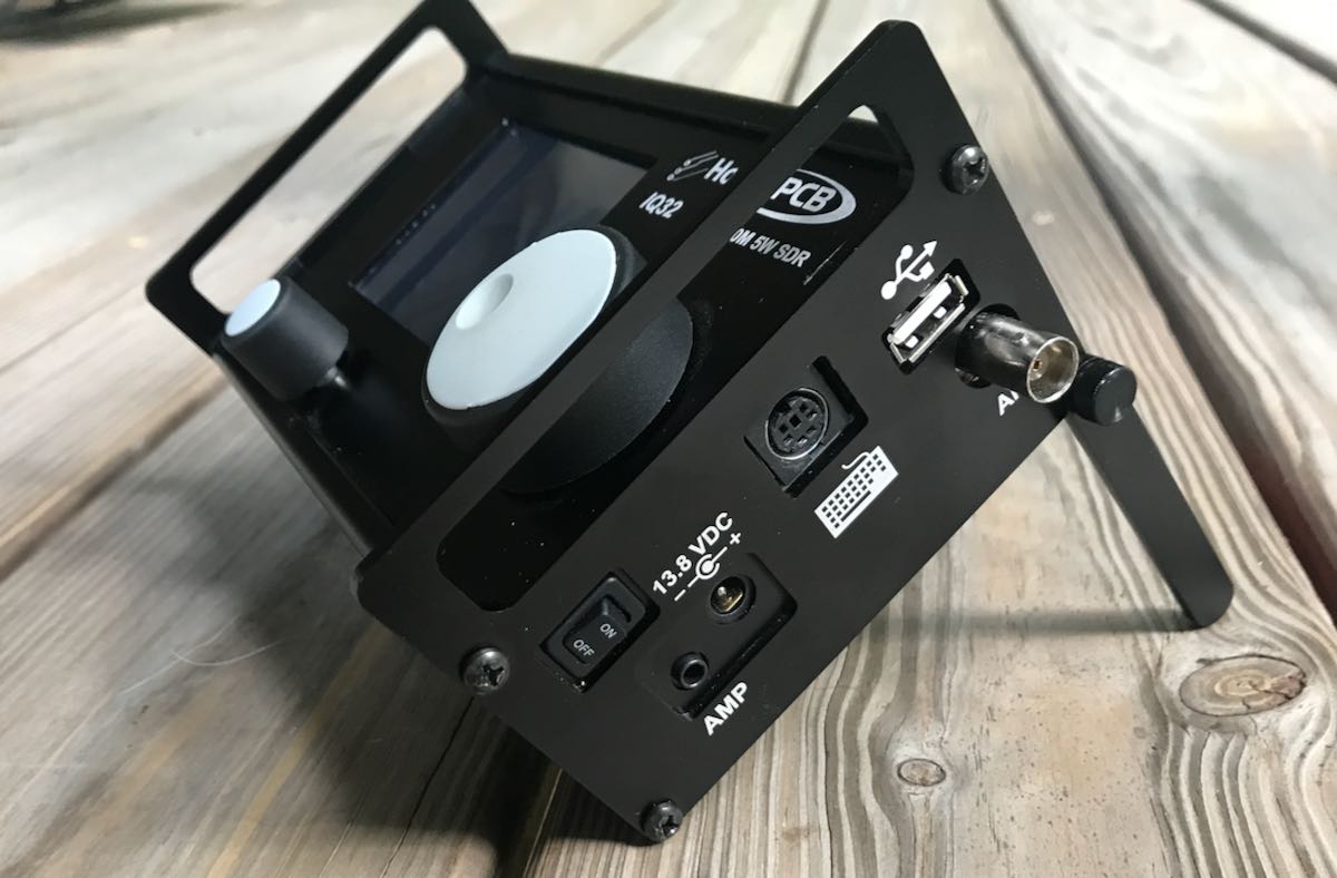
The amazing thing about the QCX+ is you getting a full-featured single band QRP transceiver for $55 US plus a modest shipping fee. This means pretty much anyone can afford to buy and build one.

I just placed an order for the transceiver ($55) with a 40M band module, the optional custom aluminum enclosure ($25), and the optional GPS receiver ($23). If I had a 3D printer, I might have skipped the enclosure because I’m willing to bet that shortly after the transceiver’s release, someone will share an enclosure design one can print at home. Then again, since I know I’ll take this little rig to the field, an aluminum enclose will provide excellent protection.

I purchased the optional GPS receiver because I plan to eventually put this rig into use as a dedicated WSPR beacon. The GPS module will calibrate the frequency, time, and Maidenhead Locator grid square in WSPR mode. It can also be used to precisely calibrate the transceiver’s synthesizer reference oscillator.

Kit anticipation time!
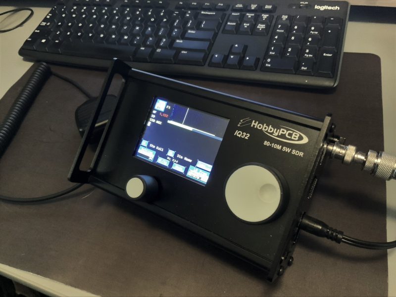
According to the QRP Labs website, they plan to start shipping the QCX+ in mid-June. I opted for FedEx delivery, so hopefully it’ll arrive sometime around my birthday (Happy Birthday to me!).

More than anything, I simply enjoy building kits and really look forward to building the QCX+, then putting it on the air! I’ll post updates and a few photos here, but look for my full review likely this fall in the pages of RadCom.

Post readers: Please comment if you’ve built a QRP Labs kit or have any other kits in the pipeline this summer!

Spread the radio love

Listener Post: Fabien’s love of radio which lead him to collecting

Fabien’s radio story below is the latest in our series called Listener Posts, where I place all of your personal radio histories.

If you would like to add your story to the mix, simply send your story by email!

In the meantime, many thanks to Fabien who writes:


I’ve been a radio listener since the age of 14. I was an SWL and a listener of local VHF free stations too.

In the beginning, my receiver was a poor radio-cassette, with a little segment of the shortwave bands. I used it for two years.

Then, for 16th birthday I received a Philips AL 990 shortwave receiver.

It was a great receiver because the sound was clear and it was easy to identify the stations when listening with my usual headphones–even those broadcasts with very weak signals and an unidentified language. The negative of this receiver was the frequency was not easy to see/read and I was at the same display for hours.

After my school period, I worked for two years and with my savings I was able to buy a JRC NRD 525 in Swizterland, where this receiver was less expensive and easier to find than in my country of France at the time.

The Japan Radio Company NRD 525 receiver. Photo: Universal Radio

The good with the NRD 525 is that it was easy to tune to a frequency, easy to read the display and easy to connect the receiver to another unit for decoding RTTY signals with an old computer monitor and a small EPSON dot printer.

I was in paradise!

But the NRD 525 has a problem with its sound. Even with my best headphones, I was not able to understand the station voices when the signal was poor and the language was not mine, so it was difficult to have sufficient details to make a good reception report for sending it proudly to the logged radio station.

My solution was strange but the only one possible : I searched for rare signals with the NRD 525 and after I found them, listened to those signals with the AL 990 and my headphones.
With this solution, I was able to send a lot a reception reports and receive some beautiful QSLs from official, pirate and clandestine stations (clandestines were my favorites).

This SWL period was until 1988. In 1988 I was obliged to move from my city to a new location where it was more difficult to be a SWL. The following years, I was more a BCL (Broadcast Listener) than an SWL.

I did BCL DX until 1999, and after 1999 most of my radio listening time was only BCL easy listening, without looking for weak signals.

Because of the Internet, online SDRs, and the closing down of a lot of broadcasters, I’m less  interested in contact stations directly, save from time to time. For me, the chase of weak signals was the most important part; now we can listen to a station via the Internet (online on a website or with a SDR online)…even the pirates stations.

My actual interest today is to have all of the receivers I was dreamed about when I was a teenager. In 2020, at 53 years old, I am now more a collector of receivers than a real BCL. I like all electronics, including many hifi systems/components and radio items.

I also love black and white film photography/laboratory too and I collect stickers from French radio stations.

Here are two pictures of part of my actual listening post. On one, you could see a model boat of the famous offshore radio station ” Radio Caroline “.

My favorite shortwave receivers are the Drake R8-E (European version of the R8), the BEARCAT DX-1000 and the Yaesu FRG-7.

My favorite receiver for synchronous detection reception is the SONY ICF-2001D (the European version of the ICF 2010).

To receive mediumwave stations, I prefer my JRC NRD 515 connected with an Australian active loop antenna.

For travel, I use a small Lowe HF 150.

For VHF FM-commercial band, I use my Grundig Satellit 500 and a Sony ICF 6800W.

Some of my best souvenirs/memories of SW reception are Radio La Voz de Alpha 66 (USA), Radio Venceremos (El Salvador), Radio Botswana, Radio Bardaï (Tchad or Libia), Radio RFO Tahiti, and Radio Bandeirantes (Brasil).

My regrets from the years 1981-1988 are not being able to receive the signal of Radio BHUTAN and the signal from The Faklands Islands.

I don’t like to travel outside my beloved country, but for the pleasure of visiting some radio stations, I made an effort and I traveled to Phnom Penh (Cambodia), La Habana (Cuba), San Salvador (El Salvador) and Ciudad Guatemala (Guatemala).

Truly Yours,
Fabien SERVE, in France


Thank you, Fabien, for sharing your story! You’ve added some truly classic receivers to your collection over the years!  I love the Radio Caroline model too! 

I encourage other SWLing Post readers and contributors to submit their own listener post! Tell us how you became interested in radio! 

Spread the radio love

Build an SDR station and balcony antenna farm for less than 150 Euros

UPDATE 11 May 2020: We recently learned that the MSI.SDR software defined radio dongle in the following post and tutorial is a clone of the SDRplay RSP1 SDR. We did not realize this when the post was published. Grayhat had done research prior to purchase and believed it not to be a clone, but only using the same chipset as the RSP1 (hence the compatibility with SDRuno). We have confirmed that it is indeed a clone now via SDRplay (clear here to read more via the excellent RTL-SDR blog). What follows isn’t an SDR review. Indeed, Grahat’s post has little to do with the receiver and much, much more to do with building proper antennas! We’ve removed links to the MSI.SDR and would encourage you to invest in the excellent SDRplay RSP1a instead (click here to read our RSP1a review). Thank you for understanding!

Many thanks to SWLing Post contributor, Grayhat, who shares the following guest post. He lives in Italy and has been in lock-down since the beginning of the pandemic. He pitched the idea of building an entire SDR setup from scratch–receiver and antennas–for less than 150 Euros (roughly $163 USD). I thought it was a brilliant idea and I believe he thoroughly enjoyed the challenge of sourcing the components and building a mini antenna farm on his balcony while in quarantine:


From Zero to SDR

by Grayhat

What follows doesn’t pretend to be some kind of “definitive guide” or “last word”, on the contrary, it’s aimed at people who have little or no experience with SDR but want to try putting together a decent station without paying an arm and a leg.

The idea of writing this came to me after reading a number of messages and discussions on various online groups/forums, in a lot of cases, someone bought an SDR (usually the ones coming with a telescopic whip antenna), and after connecting it was expecting it “just to work” or, better said, pretending that the SDR connected to that whip (usually placed on a table right near the computer) could receive ANY POSSIBLE signal, including transmissions coming from the “dark side of the moon.” 🙂 Those folks got scared by the fact that the SDR “didn’t work” and decided to give up; now, this short “guide”  should allow anyone to setup what’s needed to have a working SDR

My self-imposed limitations for this project/experiment were the following:

  1. The whole setup shouldn’t cost more than 150 Euros so that, if after trying the SDR one doesn’t like it, (s)he won’t have paid $$$, otherwise, if (s)he decides to keep it, the resulting station will allow for further expansion/improvement
  2. The available space was considered to be that of an apartment, that is, no large field to put up huge wire antennas or to raise towers, the limit was the one of a balcony (in my home) that is 8 meters (max antenna length) by 3 meters (available height) by 2 meters (balcony width)
  3. The whole setup should be simple and straightforward, no need to solder components or to build special types of antennas
  4. Given the current Covid-19 sheltering, most components should be available online, while for others one may arrange with whatever is locally available (e.g. duct tape)

With the above limitations in mind, I took pencil, paper and rubber eraser (high-tech instruments, indeed) and started writing down a list of the needed stuff, after some writing, wiping and second thought, I came out with the following list, available on Amazon:

Bill of materials

The above includes all the needed stuff to put together a number of wire antennas (random wire, random dipole, loop…) the coax to connect the SDR, a balun to match the coax to the antenna and the accessory parts needed to put up the antenna. The selected SDR isn’t the common “RTL SDR” type, not that they don’t work, but their 8 bit ADC is far from being a good performer, so I decided to pick a different SDR which offers a 12 bits ADC and which also “presents itself” to the system as an SDRplay RSP1.

[Please note: we’ve since learned from SDRplay that the MSI.SDR is indeed a clone of the SDRplay RSP1. Here’s a post from the RTL-SDR blog confirming this. We recommend purchasing the RSP1a as a better alternative.]

Anyhow; all I can say is that after some tests, the MSI.SDR is a quite good unit and offers quite a lot of bangs for the buck, so I believe it may be a good unit for people willing to get their feet wet with SDRs

The above being said, here’s a pic of the MSI.SDR unit with the included stuff:

The unit is very small and the box has two connectors, an SMA for the antenna and a micro-USB (like the ones used in cellphones) for the USB cable which is used to both power and control it; the other bits are the telescopic whip antenna (around 98cm fully extended) with a magnetic base and a short run of coax, and the USB cable.

Once I got the SDR I decided to give the included whip antenna a try… well, to be clear, while it will allow you to pick up some strong local FM stations and maybe a bit else, it will only be useful to test if the SDR unit is working (before putting together our antenna), so don’t expect to receive much with that whip, yet… don’t throw it away, it may become useful (more later).

The other important piece is the BalUn. I picked a NooElec “Nine to One” v2, since I’ve used their v1 model and I’ve found it to work well, I decided to pick the newest model which has a better antenna wire connector.  The BalUn, which is in effect a so-called “transformer balun” is really small and the junction box I bought is much bigger, but it isn’t a problem. All in all, the box may host a preamplifier in the future, but for the moment it’s fine for the balun. The following pic shows the balun “installed” inside the junction box:

The scissors are there to give you an idea of the sizes; to put together the whole thing, I started by preparing two pieces of wire (the 2.5mm one),  made a turn with each wire and locked them with a nylon cable tier. Those turns will prevent the wire from sliding out and putting a strain on the balun connector.  I did that since I didn’t have plastic washers at hand, otherwise you may just slide two plastic washers (or proper diameter) over the wires and use two nylon tiers to lock them. In either case, the idea is that the “loops” or the washers won’t slide through the box holes and will support that (little bit of) strain caused by the wire connection.

Next, I stripped some of the insulation from the ends and connected the wires to one of the balun connectors (I chose the one in the pic since I believe it’s the most suitable for this setup), at that point I continued cutting the smaller “ring” of the box insulation caps (the two at top and the bottom one). Then I placed a piece of carboard roll (from a kitchen-paper roll) at the bottom to serve as a support (you can see it below the balun). At that point, I slid the balun SMA connector through the bottom hole and used the SMA to BNC adapter to hold it, done so I slid the two wires (connected to the green wire connector) through the side hole and then inserted the connector into the balun. I then placed the other piece of paper roll above the balun and closed the box with its cap. As a note, to properly close it, start by inserting the screw into the cap holes till end, so that they’ll extrude from the bottom, then place the cap over the box and tighten the screws–you may need to use some force to properly tighten it.

Notice that the wire shown in the pic are SHORT, later on I replaced them with longer wires (outside the box) to be able to better connect the balun box to the antenna, but the remainder of the build is the same.

Now that I had my “balun box” ready, I measured the antenna wire and, using the paracord and some nylon tiers, I installed it. I also installed the “counterpoise” wire. For the latter, at first I tried just connecting the remainder of wire to the “gnd” of the balun, leaving the spool laying on the floor, but later on I decided to hang up the counterpoise and the final result was the following:

Click to enlarge

Not a work of art, but then since I was experimenting, I decided not to add PTFE and tape to allow me to quickly rearrange the antenna to run other configurations, yet, the whole setup worked quite well and stood fine to some wind and rain, the picture below shows the balun box with the antenna/counterpoise wires and the coax with the snap-on ferrite chokes.

Click to enlarge

Notice that to avoid putting strain on the balun wires, I used a wire clamp I had in my junkbox–the clamp is then tied to the paracord using a nylon tier and the paracord holds the assembly and keeps the antenna wire in position. The ferrite chokes aren’t properly seated, and I’m planning to remove and re-place them, but for the moment they’re okay. The balcony faces to south/south-west so the antenna has a free horizon of about 270 degrees ranging from the Adriatic coast to the Appennines (Mt. S.Vicino can be seen behind the paracord)–not bad. Here’s another pic showing the horizon to West, just to give you an idea:

Getting back to the antenna installation, the other end of the antenna wire is tied to the opposite side of the balcony as shown below (let aside the tent/awning, I raise them when using the SDR, also, the bowline knot isn’t correct, I’ll need to tie that again):

The counterpoise instead is supported by a lamp I’ve on the terrace, here’s it’s setup:

The “paracord” goes down to a plastic bottle filled with a water/chlorine mixture which serves to keep it in place. The remainder of the wire is just hanging down for about 1.5 meters (the counterpoise is shorter than the antenna wire, it’s about 2/3 of its length).

Ok, time to put the antenna and SDR to test, so I brought the coax inside home, connected the other SMA to BNC adapter to the SDR and connected the coax going to the antenna. Note that 15 meters of coax is enough for me, but if one wants a length of up to 25 mt, it won’t be a problem.

I already installed the SDR software, in my case since the unit identifies itself as an “SDR1” I downloaded the SDRPlay “SDRuno” software https://sdrplay.com/windl2.php and since I was at it I also downloaded the PDF manual https://www.sdrplay.com/downloads/ and the “CookBook” http://www.nn4f.com/SDRuno-cookbook.pdf and I heartly recommend reading and digesting them before starting the whole thing (while you wait for all the stuff to be delivered). An important note is that you MUST install the SDRuno software BEFORE connecting the SDR since that way, the SDRuno setup will install the proper drivers and you won’t have issues.

Anyhow, I connected the coax to the SDR and then it was time to fire up the whole thing and give it a spin; so I powered up the laptop (technically, a “transformable” laptop/tablet), started SDRuno, opened the “RX control” and “Main Spectrum” windows and then clicked the “play” button, clicked the “broadcast” band, and the “MW” one and got this:

Not exceptional maybe, but not bad, either; in particular if one considers that it’s from a quite short piece of wire which isn’t exactly placed in an ideal position.

Deutsche Welle

So I went on and explored the bands a bit. On ham bands the SDR picked up signals from the whole mediterranean basin (Cyprus, Lebanon, Spain and then some) and from north too (Russia, Germany, Denmark); then depending on time, I was able to clearly receive broadcasts from China, South America, Africa and more ham QSOs from a lot of places.

BBC Ascension Island 5/9+ and just a bit of QSB

I must admit I didn’ record the callsigns or stations identifiers (“guilty” your honor–!) but I was more focused on testing the SDR and antenna than running a “DX session” at any rate.  On the BCB bands I picked up WWV, BBC,  VoA, China Radio International, Radio Free Asia, Radio Romania and a bunch of others from Middle East, Asia, Africa and South America. While on the ham bands, I was able to pick up some quite interesting QSOs and then… well, I went hunting for higher frequencies signals!

I got Police, Ambulances, Air control…so even if that “piece of wire” isn’t optimized for VHF/UHF it seems to be working decently there too. By the way, when changing bands you may (and probably will) need to adjust the gain control, but that will be almost the only thing needed to pull in signals

At the end of the day, I can say that I’m quite pleased with the performance offered by this simple and cheap setup. For less than 150 euros you have everything you need, not just the SDR.

Sure, the setup may be improved, but then again you’ll have all of the basic parts, so you won’t need too much. For example, if you live in a really noisy environment, it would be a good idea to use a loop antenna. You would only need a “cross shaped” support (PVC pipes or wood will do). You could quickly put together the SRL (Small Receiving Loop) designed by Matt Roberts (KK5JY) http://www.kk5jy.net/rx-loop/ the balun will be the SAME (yes, no need to wind whatsoever!) so building it will just be a matter of assembling a cross shaped support for the wire (which we already have because it’s the same used for the wire antenna) and you’ll have it. While I already tried the SRL, I didn’t build one to test with this SDR, but I’ll probably do that as soon as SWMBO will start complaining about those “wires on the balcony.”

Also, at the beginning I wrote “more later” when writing about the telescopic whip included with the SDR. Here’s the idea–it requires soldering, so if you don’t want that, skip this: remove the adhesive sheet on the bottom of the antenna base to expose the bottom cap and then remove (extract) the bottom cap. You’ll see a magnetic ring and a “bell shaped” piece of metal (the “ground” for the whip). In the middle of the “bell” there will be the antenna connector which is soldered to the coax wire with a nut holding the connector (and the “bell”) in place. De-solder the coax, unscrew the antenna connector and extract it, at that point you’ll have the telescopic whip and its connector, now you may use them to build the active “whip” antenna described here:

http://www.techlib.com/electronics/antennas.html#Improved%20Active%20Antenna

Notice that it is NOT the “usual” active whip–the circuitry and idea behind it is totally different–yet it works fine and will serve you from VLF (not kidding) up to around 100MHz. It might be a good companion for the SDR. It won’t be as quiet as the loop, yet it may be a valid “all rounder.”

To conclude, I believe that the setup described above is something anyone can afford. You don’t need to be an engineer or to have special knowledge or abilities–it’s just a matter of putting together some bits and pieces.

Obviously, this setup doesn’t require a large space and offers good performance across the bands. Plus it’s so easy to improve since the 12bit SDR is a good starting point

All the best everyone and STAY HOME, STAY SAFE !


Thank you so much, Grayhat!

I love the fact that you invested (however modestly) in a proper antenna setup to better serve you rather than relying on the basic whip antenna that comes with the SDR. You’re right: too often, we invest a receiver, yet invest no money or time into building an appropriate antenna.  The antenna is the most important component in a proper radio setup and those included telescoping whip antennas simply don’t perform well on the HF bands.

Based on our correspondence, I know you had fun piecing together this little system using a simple bill of materials and items you had on hand during the Covid-19 quarantine. Thank you for sharing it here with your SWLing Post community! 

Spread the radio love