 By 13dka
After all the recent buzz and watching and reading every video, review, and discussion thread/group I could find about this radio, as per usual, I knew I had to buy one in order to find out if I want one…again. This is not a review, but taking notes while getting acquainted with it and gathering the technical information I couldn’t find, I started thinking that sharing this might be at least entertaining for other MLite owners, maybe helpful to elaborate on a few things for newcomers to complex radios and SDRs on the way and also to tell the undecided why I started calling it names so I had to keep it. Sounds terrible and very much like a review, so let’s get on with it.
Chapter One: What is this thing anyway?
I couldn’t help noticing the higher-than-usual pile-up of “game changer”, “new era,” or “the radio <brand name> never made” expressions coming with this one, and I was confused. Sure, it is another small, self-contained SDR, functionally more or less just a mildly simplified Malahit redesign with a much simpler display in a more familiar shape, but the Malahits have been around for years, and they’re neither the first nor the only radios with this job description. I couldn’t quite understand what fueled the sudden interest, just because it doesn’t look like Spock’s preschool tricorder and more like the offspring of an Asian travel radio and a Scandinavian business phone? Really? Then I found the price tag and the light came on.
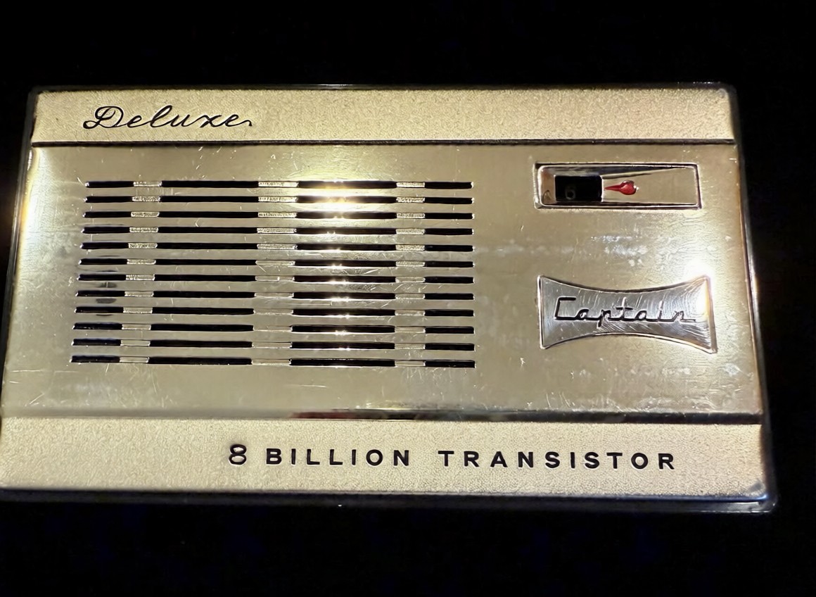 That it’s now also much easier to purchase the new Gründig Sputnik 880 as an official product with authorized firmware from Malahiteam’s new Chinese manufacturer obviously did it for me too, and it may speak even more to people who have really been waiting for an affordable, actual step-up from their first 473x-chip radio for so long that they bought 5 more of those in the meantime. I promise it may be quite an upgrade from any radio that looks similar, and I even deem it pretty user-friendly. However, it’s technically and conceptually still a Malahit and as such much closer to any other SDR hard- and software made to cater to the exotic desires some outspoken radio enthusiasts have, than to anything it is made to look like.
Unfortunately, this is really clashing with very frugal documentation and unusual technical secretiveness about what’s in there; people have to figure out many things on their own and fail at it, and I feel the mimicry is also fueling unrealistic expectations.
Chapter Two: Technical Notes
The “technical secretiveness” extends to filing the markings off most chips, so little is known about the innards of this receiver. Russian YouTuber Alexey Igonin suspects a single-conversion SDR on shortwave (up to 27 MHz) becoming a dual-conversion radio above. The FM broadcast range appears to be a separate tuner active between 65 and 107.999 MHz and another VHF tuner from 108-165 MHz; both tuners are then downconverted to the high IF of the SW receiver. This abstract string of words explains to the initiated why oddities may be seen here and there, for example, when you tune to 108.00MHz
Operating concept
For a general description of the radio, menus, and general operation of the MLite, please refer to Dan Robinson’s and all the other excellent reviews. I want to sell you on the general concept centered around the telephone keypad, making it strangely not such a big deal for me that it has only one encoder knob and 16 buttons. It’s quite different from all button portables I have met:
Each function menu has its own button, assigned to 9 of the 12 buttons on the phone keypad. Each function in these menus has a number, too. That means you can memorize access to your frequently used functions by a 2-digit number, one for the menu, the other for the item you want, and in many cases, that’s all. Dial 25 for AM, 26 for SAM, 21 for USB without further action, 61 is the number of the IF filter warehouse expecting your orders via the knob (unless it isn’t), you get the idea. That means most functions on this radio have 2 buttons you need to tap, but they all have their own 2 buttons right on the front panel.
Direct frequency input is activated by button [4] and is accepting a couple of ways to enter a frequency followed by button [A] for kHz and [B] if you want MHz, e.g. “123*125 [B]” or “123125 [A]” take you to the same frequency, or just hit “123 [B]” to go to 123 MHz and tune up a little. Some even recent radios are much less tolerant and made me give up on typing in frequencies; this is not one of those.
Such an anachronistic flashback to early digitally controlled commercial radios/machines/things or DOS computers seems to be almost ironic on the face of this bundle of latest digital wonders. But I think it could easily run circles around nested menus on a tiny touchscreen if you can adapt to it. The keys are not backlit but if you could dial 911 in the dark on an old landline telephone like the victim in an old crime show episode, you can position your fingers on the keypad to type “4-27555-A-21” (hyphens for clarity, it’s actually 42755A21), if you have firmware 1.5 or higher this will take you to the CB “highbander” calling channel in USB, hopefully entertaining you until the ambulance arrives.
Unfortunately, there are also multi-page menus like the [AUDIO] page with your filters, so “61” doesn’t always work, and e.g., the steps menu changes its buttons according to the mode, so the “mental phonebook” method becomes a little more involved. Still, when you exit and return to a menu it will still have that previously selected function assigned to the encoder to speed up things and it memorizes that for each menu individually, long press of the SQL [B] or NR [C] button (while they’re on!) takes you directly to their intensity setting in the menu…in short, things have been laid out very well and after a few days that became part of the fun this radio is. Summary: It’s a real asset because it allows you to fly this radio blind, for example, when you’re legally blind or just legally supposed to have your eyes on the road.
Antenna Input, Impedance Switch, and Bias-T:
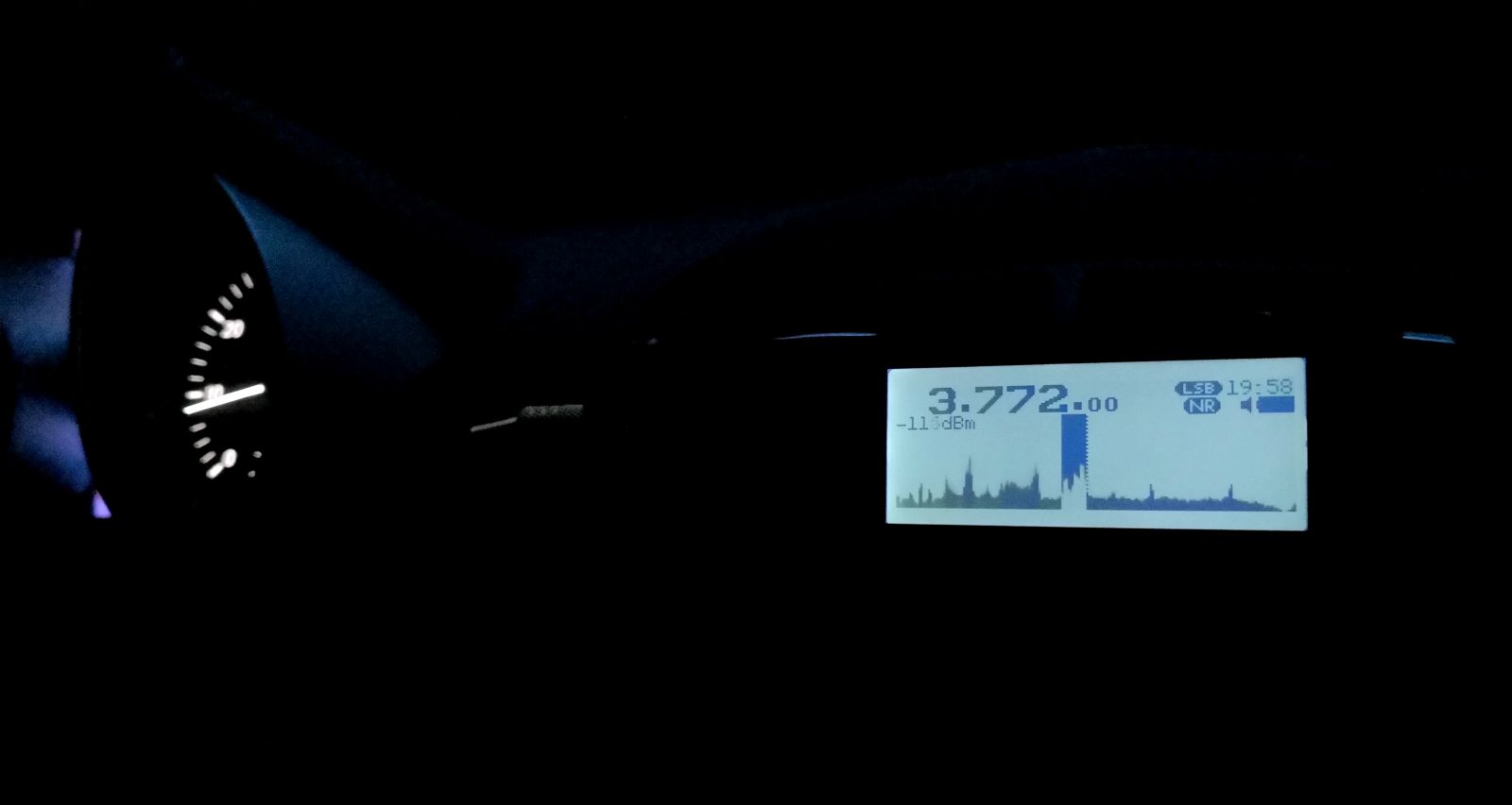 An understandable common misconception seems to be that the antenna switch [3][1] is toggling between the whip and the 1/8″ phone-type antenna jack. What actually happens when you insert a phone plug is that the whip is getting disconnected, and the switch is toggling between high and low input impedance. It seems rather important to understand that this high impedance input is provided by the additional amplifier needed for the whip; it remains in the signal path when you use the antenna jack.
In general, switching impedance allows for external antenna configurations that would otherwise not work well, and in the presence of high local noise levels, the shielded input is highly preferable over open wires alligator-clipped to the whip in lieu of a missing Hi-Z input. Besides matching different antenna types, switching impedance can also increase the number of “good” frequency bands on the same (passive) antenna. Most antennas, including simple passive wire antennas like endfeds etc. exhibit a wild up and down of impedances over the wide range of wavelengths we SWLs use them on. When the impedance mismatch happens to be at its most loss-inducing extremes in the band of our choice, switching the input impedance may or may not improve reception:
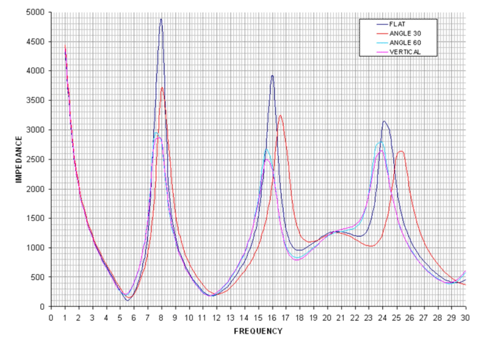
VK6YSF’s impedance vs. frequency plot for an endfed antenna in different orientations
For example, a simple magmount whip on the car roof is often all you’d need for a bit of quality mobile SWLing, but impedance mismatches between the external whip, the cable, and the input can suck the life out of it on many frequencies. My “Little Wil” CB magmount doesn’t work well on 20m…switching to Hi-Z can fix this. In other bands, this will not improve anything, and the MLite is kind of giving a clue on this bad constellation by becoming very noisy when you switch to Hi-Z in these cases.
The additional amplifier helps with these small, lossy antennas, but that advantage can turn into the opposite when it gets overloaded by “full-size” antennas, and the simple logic “Hi-Z antenna works best on Hi-Z input” doesn’t always work anymore. Leaving this for everyone to figure out on their own is provoking bad results and bad rep.
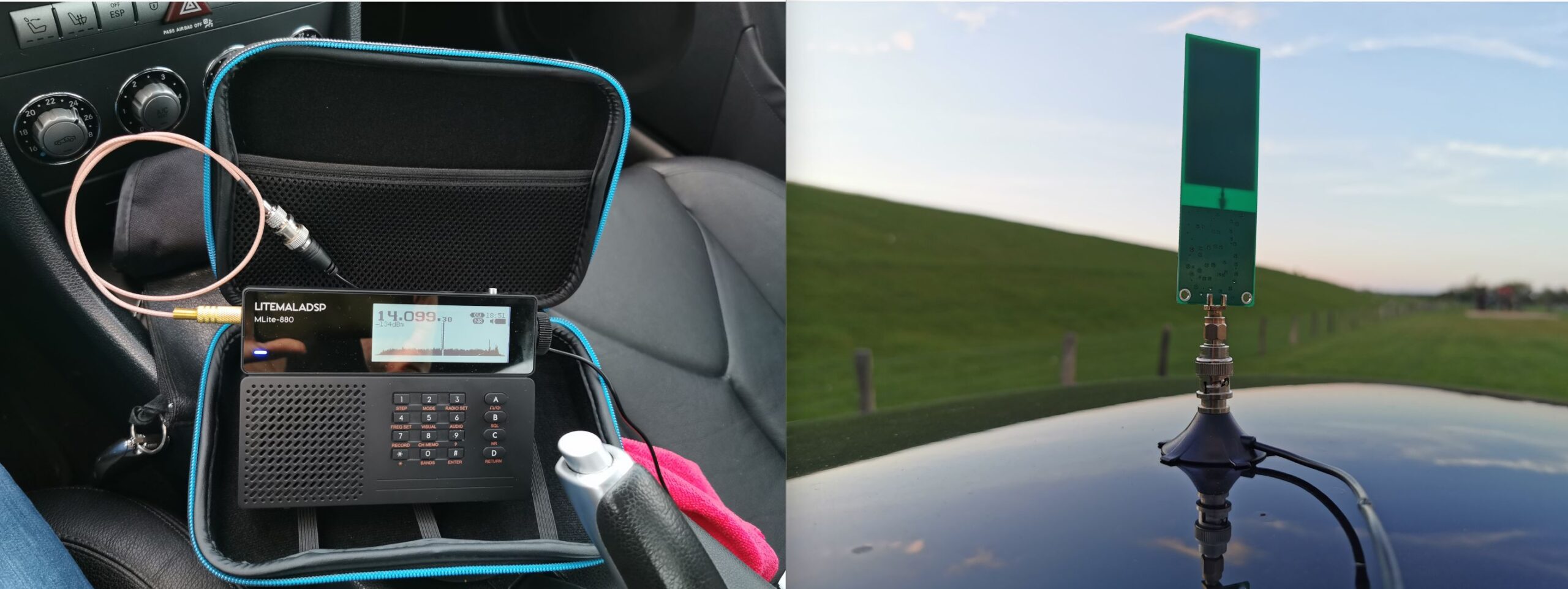 This radio offers to pass the (unregulated, drops during discharge!) battery voltage to the antenna jack for active antennas and LNAs at no extra fees. I could finally try if a tiny miniwhip could be a worthwhile low-profile solution for the car roof, one that gets enough shortwave in while keeping the considerable electromagnetic racket within the car out. Turns out the 15 bucks drawer-queen miniwhip PCB that was once powered up for 10 seconds 10 years ago seems to be pretty happy with sitting on a car roof, it works almost as well as a 47″/1.20m telescopic whip while theoretically giving a very low profile, avoiding the RC-car looks. Too bad nobody makes an autobahn speed compatible, magmount miniwhip for cars, hint, hint, nudge, nudge.
Spectrum Display
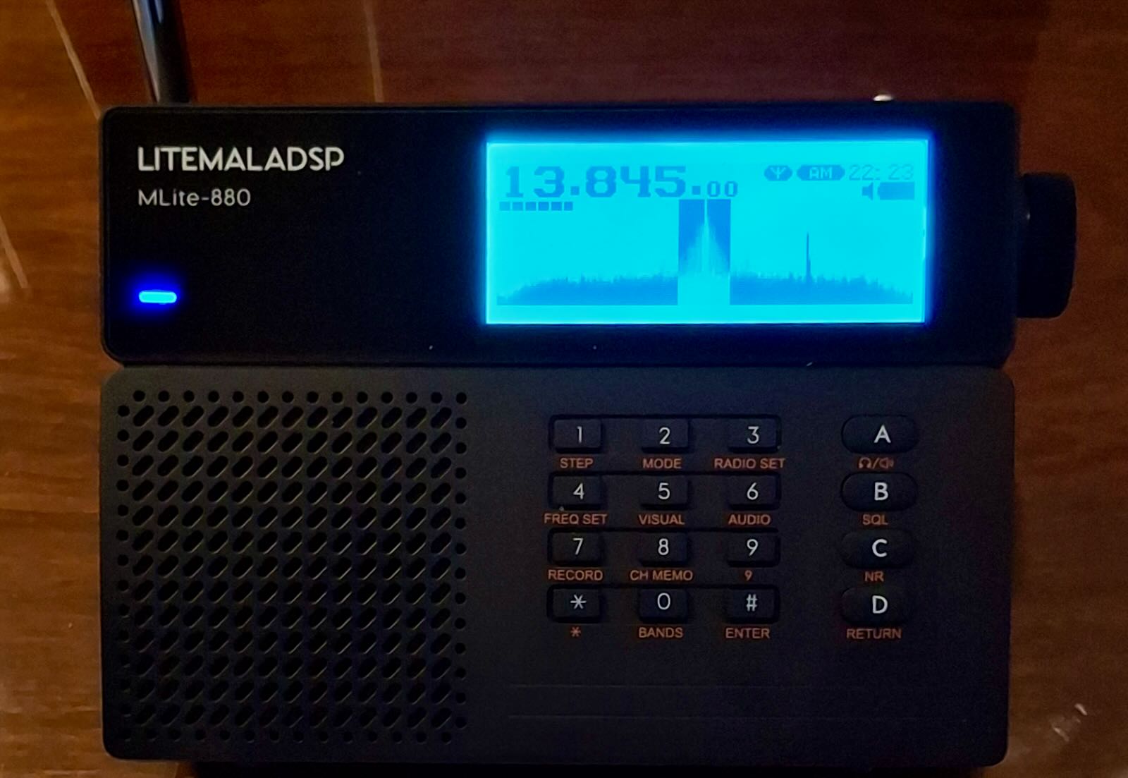
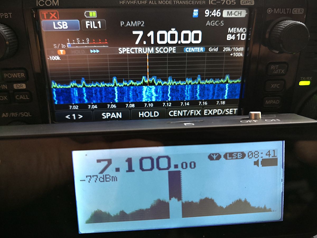
If the Panicsonic RF-KGB-65 is your first radio with a spectrum display, welcome or welcome back to the world of radios that have something nice to look at. I appreciate the feature too, and maybe it’s a good thing that it doesn’t overwhelm people with information, but a spectrum graph line without scale/grid to tell how wide, far apart and strong signals are on that spectrum does not provide very much information beyond revealing the pure existence of something left and right of your tuned frequency. Still a great thing to have and a mesmerizing and instructive eye catcher and only a white cat can make you look more like someone out of a James Bond movie while consuming almost no battery.
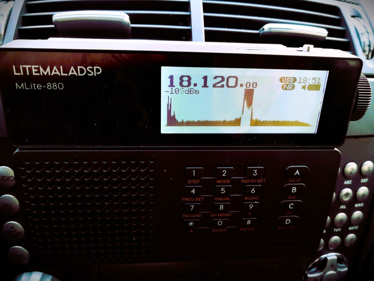 How much of the spectrum you can see depends: What you actually get anywhere on AM/SW/VHF is a 40 kHz portion of the band, and you can’t zoom in or out, likely because that’s how much you can reasonably expect to show on a low-resolution dot-matrix display, expecting narrowband signals on the band. Narrow signals are also why the spectrum line should be filled, or unmodulated carriers/CW will be represented by a single, hard-to-see dot instead of a full single line. In WFM we get roughly 600kHz of spectrum from that display, which is just the FM equivalent of “not an awful lot”. On the plus side, you almost never have to bother with spectrum settings (which can be a rabbit hole, trust me).
Averaging means that the height of each dot in the spectrum line is calculated off more samples, the more samples, the longer they live on the display, too. This allows the display (and us) to differentiate between weak signals and noise. I found the most useful averaging settings in the upper half of the range 50-99, not quite as good as a waterfall display (= a history of spectrum plots), but ’99’ will allow you to blink very slowly and not miss an activity, at the cost of display responsiveness. Too little averaging also makes you miss fast events on the “bandscope” even when they’re loud.
To alleviate you from more settings, the radio is automatically scaling the levels of the spectrum line. If a strong station comes up within the spectrum passband (not necessarily within the 40 kHz display range), the scaling changes and the visual noise floor drops. This looks confusingly the same as if the AGC was “pumping” and radio would be actually desensitized by that station. This can actually happen, but then you will also clearly hear the AGC “pumping” the noise floor as the display seems to indicate. That scaling also means that the visual noise floor does not reflect the actual level or proportion of the noise floor; deriving SNR differences from the graphical representation is not always possible.
Both spectrum and signal meter displays seem to indicate frontend input levels pre-AGC; changing the gain in the radio does not affect the display (the built-in attenuator does, of course). Besides the spectrum, the display has the usual status indicators but the very limited display space may not allow for all indicators people could wish for. The bargraph signal meter can be switched to an alphanumeric dBm display aligned with the classic S-meter 6 dB/step scale (not dB/?V) as indicated by the meter refusing to measure signals beyond -73dBm (S9), in which case it just notifies you of the surplus level by adding a ‘greater than’ sign to the value, “>-73dBm”. Still, the numerical measurement is pretty averaged/integrated and therefore nicely readable below that. Which is good because the meter does indicate the noise floor.
Controlling Gain, AGC, and ATT:
Most of the radios the MLite-880 is cosplaying have an AGC that doesn’t require any interaction and many of them just have a “one size fits nobody” response curve for AM and SSB. Likewise, most portables don’t have gain control beyond a “Local/DX” switch on the side. The MLite AGC, on the other hand, offers 4 release speeds with variable ‘Gain’ and ‘Limit’ parameters, plus a manual gain control option.
Of course, I’m pulling this out of the nose since it’s all not documented, based on my observations and similar arrangements: In very simple words, ‘Limit’ sets how loud you want the loudest stations to be, and ‘Gain’ is how loud you need to have the weakest station, particularly in SSB.
To elaborate on that, ‘Limit’ sets the threshold level where a signal causes gain reduction, and ‘Gain’ is basically the “RF gain” control some people think is missing on this radio, giving remarkable gain reserves (60dB). Use ‘Gain’ to bring weak stations closer to the ‘Limit’ threshold. “Limit” defaults to “75dB” and it looks like signals around S9 are going to be, well, limited to that, which means raising that is lowering the overall AGC action as much as decreasing gain while it increases the volume. The closer these two values get to each other, the more compressed, noisy, and “pumping” the channel will sound. Keep in mind that gain does not equal sensitivity, and avoiding AGC action is often preferable over the convenience of not needing to touch the volume knob. Matching gain to the conditions and signal you want to receive is also a prerequisite to make the most out of the noise reduction. This old clip demonstrates the difference it can make when you can control gain to avoid getting loud signals squeezed by AGC and the noise floor not being pulled up unnecessarily (same transmission received on a D-808 (no gain control) vs. a Belka (has gain control), recorded simultaneously):
A sound like this is the sign that you may want to reduce ‘Gain’, or use the attenuator (dial “33”) to that effect.
I’m not sure I understand or experience all of the issues some seem to have with the AGC; other than that, it does not default to the hottest gain settings it is capable of, which adds to a different problem with this radio – the harsh drop in volume in SSB/CW and WFM modes compared to AM/SAM/NFM. That also might be pushing people towards increasing gain beyond reasonable values to compensate.
The ATT can be set to 36dB of attenuation in 6 dB-steps, but for some reason, I can see at best 15dB of it on signals anywhere on the S-meter scale, high or low, which seems as strange as the fact that it didn’t help in the only overload situation I had with this radio. If this is your first ATTenuator, it’s supposed to decrease the signal in front of all amplifier stages, unlike most RF gain controls, it is often the radio’s only reliable (onboard) way of keeping the radio’s first transistors from overloading in the presence of very strong signals. Please note that it says “Attenuator for SW” for a reason: It does not work on VHF, which in this radio seems to start circuit-wise on 27.000 MHz so the 10m-band has to make do without.
Noise Blanker
Unlike most portables, this one has a noise blanker, and of course, it’s not only an on/off switch like in the old days. Invented 100 years ago to mitigate engine ignition impulses, nowadays they can be used to mitigate impulses from electric fences, OTH radar, or local PLC modem (!) impulses, which is why you can often adapt the timing parameters. Of course, this one is hurtfully undocumented again, I assume that the 3 modes of the NB relate to bandwidth presets. The other dimensionless control seems to set the timing of the countermeasure, but it always seems to work best or at all at the minimum value. Since I assume this radio attracts many buyers unfamiliar with these things, be advised that wrong and even the default settings in modes 1 and 3 can cause distortion in the demodulation when you don’t expect it, so it’s better not to leave that permanently on.
Here’s a short video showing how it works on a strong OTH radar, the noise blanker is acting in/before the IF stage so its effect also reflects in the spectrum display:
IF filters:
A big giveaway that the 880 is not to be confused with a radio is that it visually alludes to are “the filters”. Of course, in SDR, there are no physical IF filters and barely any limits to their number, shape, or properties, and it shows:
The [AUDIO] menu has 3 slots for your own filter settings named “narrow”, “normal” and “wide” and in each you can define low and a high cutoff frequencies, so that’s 3 variable filters so far. But of course, each mode has its own set of 3 “filters” you can define to your liking. The MLite-880 is one-upping this by giving AM and SAM, USB and LSB each an individual set of 3, too. WFM has 4, that’s 22 (!) places to set filter bandwidth. That’s not mandatory, of course, but still one nice source of confusion for elderly people like me and something to keep an eye on for a while.
The filter shape itself is fixed, it has less rounded shoulders than what I have in the Belka and the IC-705 in “sharp” mode, with the same quality and perceived stopband rejection of those, and that alone would be enough to lift the long-term reception experience with the MLite way above and beyond the 473x chip radios, or even the best of their small analog ancestors from Japan.
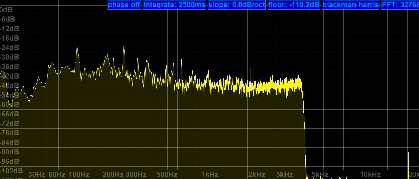
Nice upper filter slope (lower filter frequency = 0) to claim all of a 9kHz ITU region 1 mediumwave channel and still keep the neighbors out.
25m band scan on a 10m vertical at the dike. It also demonstrates that the 4.5 kHz filter setting shown above is keeping the signals 10 kHz to each side of NHK on 11,625 kHz in check (NHK also received on 11,860 kHz, both direct from Yamata).
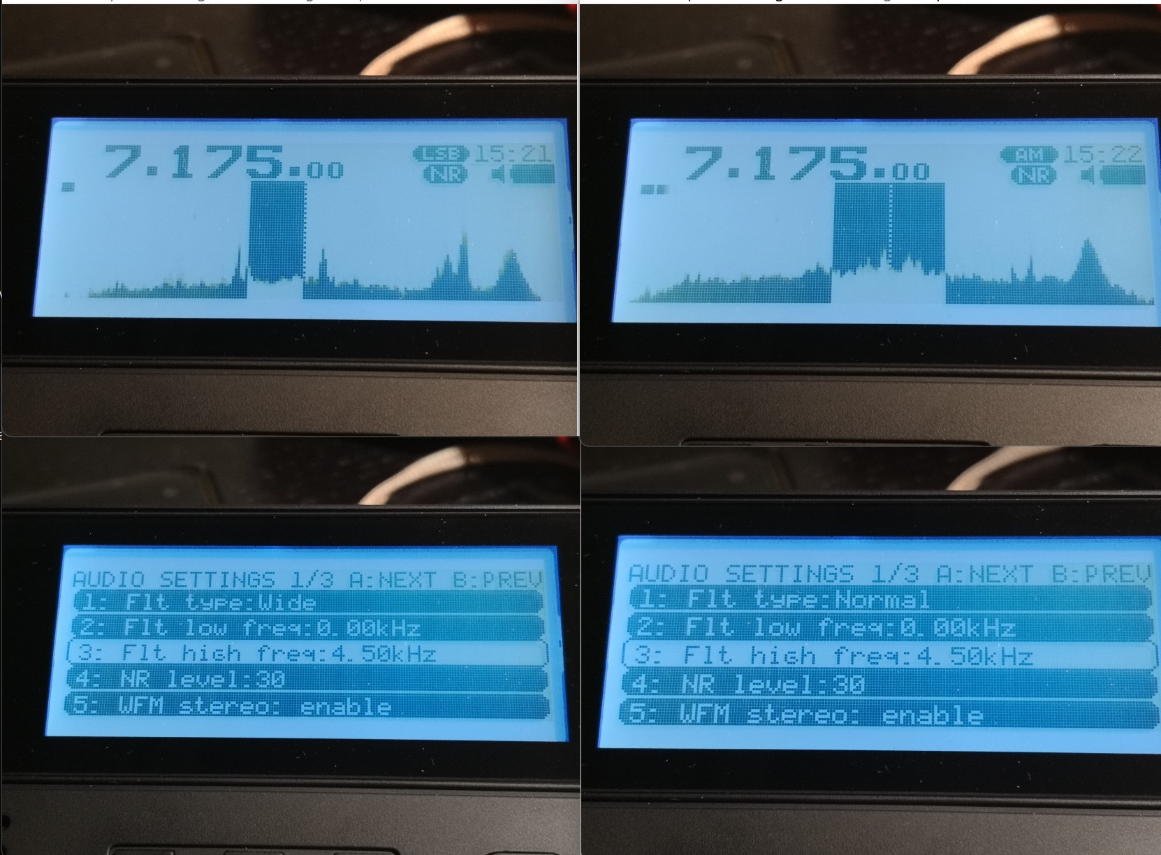
As for the mildly important question, what bandwidth is meant when you set the filters in AM – this is once again “per sideband” in AM, like on the Tecsuns: 4.5 kHz means 4.5 kHz audio bandwidth, the old-school physical IF ladder filter equivalent for that kind of passband would be labeled “9 kHz” if you want to compare that with some old rig. What sets this apart from e.g. my Icom is the possibility of having very wide sidebands up to 15 kHz for 30 kHz wide experimental AM broadcasts, also in SSB. The MLite reflects the IF filter equivalent in the width of the “dial pointer”:
 The properly narrow (>200Hz) and SNR-increasing CW filters are what make this ????? Trans-Okhotsk and the Belka the only receive-only portables with proper CW reception and a price tag around $200. Since FW 1.5, it also does CW “offset compensation”, so you don’t have to go through the hardships of subtracting your adjustable CW pitch frequency to correctly tune to a published frequency like in the Middle Ages anymore.
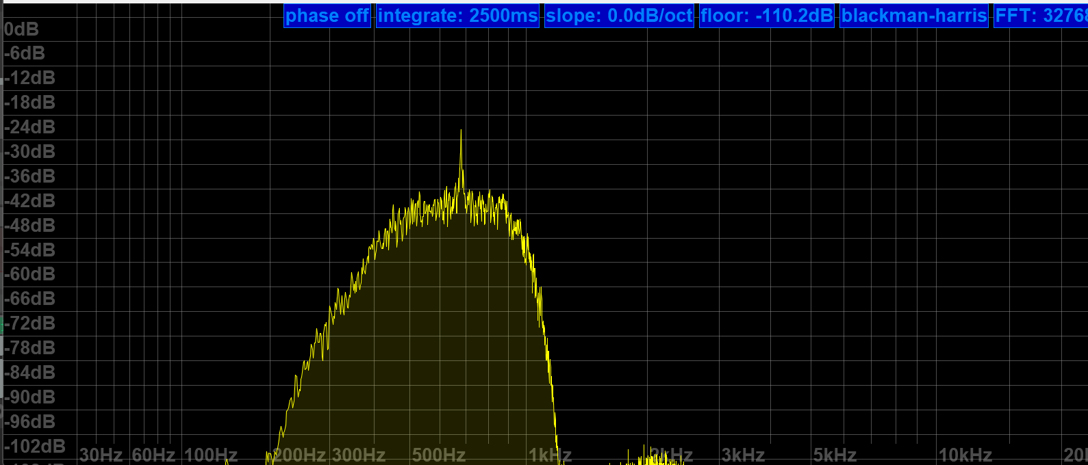
MLite 500Hz CW filter more or less centered at the CW signal at 700Hz
Frequency Calibration and Stability:
You can skip this section if you’re not much into SSB, and the following is not a complaint, just an observation and generally not a big deal, or rather part of the deal: The MLite-880 is not perfect <gasp> and it has “Lite” in the name for a reason:
Besides more obvious things, it lacks the automatic notch filter and the TCXO (temperature-compensated crystal oscillator) of the “big” Malahits. It has to make do with an XO and a lot of XOXO, and with that, it can’t quite match the linearity and temperature stability of the Belka, which is 99% on par with the IC-705. Most people are probably familiar with the need to calibrate their radios, and a few less have a radio that lets them do this, but not needing to do this is understandably one of the expectations people have with this SDR. But unlike the SW range, which is generally close enough to the nominal frequencies for most buyers, the separately calibrated VHF range seems to be in need of an initial calibration on many shipped radios; it was several kHz off in the VHF marine band on mine, too. I just tapped [3][5] and turned the knob until the station showed up right. Easy enough.
On shortwave, I’m talking about very small but occasionally inconvenient offsets/non-linearity in the tens of Hz range, nothing that makes you want to find your pocket calculator even if you’re a heavy SSB/utility listener. Calibration on digital receivers means you can fine-tune the master oscillator conveniently in a menu, and “non-linearity” means an offset varies over the course of the frequency range and does not plot a straight line. The offset is different in different bands, and you may or may not want to recalibrate there.
Calibration procedure (may not work on analog receivers!): Find a frequency standard station (like WWV, BPM, or RWM) or just a regular station with no (or a published) offset. Tune 1kHz lower than this frequency and switch to USB to create a 1kHz het. Put that in a memory slot. Tune 1kHz higher and switch to LSB to create a het again from the other side. Now get your cellphone with a free spectrum analyzer app like Spectroid or Phyphox on it so you can easily measure the frequency of the het: It should be close to 1kHz in both USB and LSB. Starting technically at 27.000 MHz, the VHF range has its own calibration setting when you go there and you ideally want to find a calibration station near the top end of the range, like a 2m repeater or something.
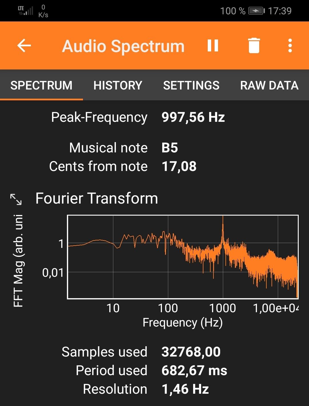
For example, the needed offset on 5 MHz is -5 on my radio, on 10 MHz it’s +64, and +72 on 15 MHz at a cozy 25°C. That means I can calibrate for a negligible deviation in the 10 and 15 MHz signals and live with a somewhat bigger offset on 5 MHz, or I can make them all within +/- 30 Hz off, which is still awesome by analog radio standards and not terrible for a modern radio, but requires fine-tuning when you need it better than that. Calculating the indicated vs. actual offsets it dawned on me that the unit used on the shortwave side is still “x0.1ppm” and the math doesn’t math, that should read “x0.5ppm” as well.
The best I can get without 5MHz being off too much – good enough!
On top of the general offset, there’s also a noticeable (at 10-15°C differential) temperature drift, making the calibration efforts less persistent outside than I’d wish for. +72 for 15MHz at home to 120×0.5ppm at 15MHz equals 24Hz of temperature drift, adding to whatever offset was there before, which can amount to “too much” and there seems to be some “ripple” in the deviation curve: Here’s a recording of CHU on 14,670 kHz somehow ending 80Hz off right after calibrating the radio on 15 MHz:
Again, not great but not terrible in the grand scheme of things because deviations below 100 Hz are only ever a factor in SSB, and it may even add to the odd charme of this radio that it is very analog and old school within a tolerable margin in this regard. But if you try ECSS reception with music, your ideal deviation is none and 10Hz at the end of “tolerable”.
Fixing the tuning emergencies when your fav song is playing and sounds terrible in SSB is done by dialing (think nine) [1][1], the useful number of the fine(st) tuning step in all modes, or just hit [3][5] and use the calibration function as “RIT” knob until it sounds right, and you will be good. It’s not a calibrated Rohdow & Shwartzkiy lab instrument, you can’t break anything, and it provides the needed fine resolution you’d need for true “zero-beating” but yes, it does feel very luxurious to switch to sideband when a $5 TCXO makes sure you can rely on the radio being spot-on in SSB when the station is, on any frequency, even in winter.
Synchronous Detector
…can’t be missing on a decent SW portable and this one seems to be a (non-selectable sideband) “PLL”-type detector and gives SDR-typical results: Remember that AM and SAM have individual filter settings so you want to make sure you match them when you compare that, but this detector is as unspectacular in a good way as it could be, it has super-solid lock and does absolutely nothing, zero, nada to the signal other than keeping the multipath distortion in check, which it seems to do very well.
31m band scan (antenna; car roof whip) with a brief demonstration of the sync detector at 0:16 seconds into the video. Note how the piano distorts when I turn it off again. Continue reading