Photos from the 2022 Milton Ontario Hamfest

Many thanks to SWLing Post contributor, Mike (VE3MKX), who writes:

The following pictures are from a Hamfest which was held yearly at the Milton Fairgrounds in Milton Ontario, Canada. (Located 20 minutes west of Toronto).

The Burlington Amateur Radio Club organizes the event and confirms that they had 108 vendor spaces sold and over 475 general admin passed through the gates.

A great day of meeting friends, lots of deals and smiling faces!

Thank you so much for sharing this, Mike! I haven’t been to a hamfest yet this year, so it’s great to catch a glimpse of what looks like a very successful one! 

Readers: This is a large gallery of 132 photos courtesy of Kevin (VA3RCA) and Mike (VE3MKX). If you would like to view the entire image gallery click on the link to see more.  Continue reading

Spread the radio love

Ken reverse-engineers the Apollo spacecraft’s FM radio

Many thanks to SWLing Post contributor, Paul, who shares the following post from Ken Shirriffs’ Blog:

Reverse-engineering the Apollo spacecraft’s FM radio

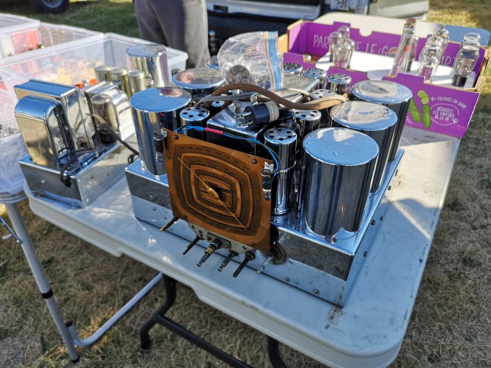
How did NASA communicate with the Apollo astronauts, hundreds of thousands of miles from Earth? The premodulation processor1 (below) was the heart of the communication system onboard the Apollo spacecraft. Its multiple functions included an FM radio for communication to the astronauts, implemented by the Voice Detector, the module second from the top. In this blog post, I reverse-engineer the circuitry for that module and explain how it worked.

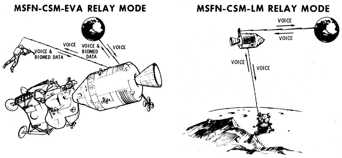
The Apollo communication system was complex and full of redundancy. Most communication took place over a high-frequency radio link that supported audio, telemetry, scientific data, and television images.2 NASA’s massive 85-foot dish antennas transmitted signals to the spacecraft at 2106.4 megahertz, an S-band frequency, giving the system the name “Unified S-Band”. These radio signals were encoded using phase modulation;3 onboard the spacecraft, a complex box called the transponder received the S-band signal and demodulated it.4

The voice and data signals from Earth were combined through a second layer of modulation: voice was frequency-modulated (FM) onto a 30-kilohertz subcarrier while data was on a 70-kilohertz subcarrier, so the two signals wouldn’t conflict.5 One of the tasks of the premodulation processor was to extract the voice and data signals from the transponder’s output. These voice signals went to yet another box, the Audio Center Equipment, so the astronauts could hear the messages from the ground. The data signals were decoded by the Up-Data Link, allowing NASA to send commands to the Apollo Guidance Computer, control onboard relays, or set the spacecraft’s clock.

Many systems worked together for communication, but I’m focusing on a single module: the voice detector inside the premodulation processor that performed the FM demodulation. [Continue reading the full article…]

Spread the radio love

Further adventures of WELK

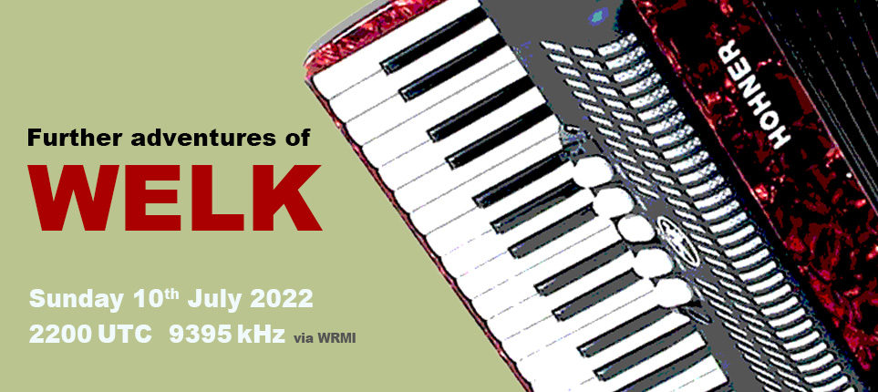
Hi to all SWLing Post community, it’s Fastradioburst23 again letting you know about the second transmission of WELK this evening at 2200 utc on 9395 kHz thanks to the good folks at WRMI.

If you enjoyed all the accordion and squeezebox based tunes last week you’ll be sure to love this second installment and it’ll be a good one to have on in the background whilst perfecting those air accordion moves.

Spread the radio love

Changes to KTWR’s DRM broadcast schedule effective 3rd July, 2022

Many thanks to SWLing Post contributor, Mangosman, who shares the following tip from Mike Sabin at KTWR via Alokesh Gupta’s blog:

Due to requests for later broadcasts, improved propagation, and the addition of a program, KTWR is changing its DRM broadcast schedule effective 3rd July, 2022.

KTWR Digital Broadcasts
DRM broadcasts (Effective 3rd July 2022):

Day Time(UTC) Frequency Coverage Area Language
—————————————————
Saturday 1100-1127 12000 kHz China English
Saturday 1128-1230 9910 kHz Japan Japanese, English
Mon-Fri 1215-1245 9910 kHz China Mandarin
Sunday 1500-1545 15205 kHz India English
Sunday 1600-1630 15390 kHz India South Indian languages

(Mike Sabin, KTWR)

Spread the radio love

Full Schedule of RTI Transmission Tests and Special QSL

Many thanks to SWLing Post contributor, Gerard Koopal, who writes:

Dear Thomas,

[Per the email message below] from Radio Taiwan International, they will bring a direct transmission from Tamsui, Taiwan in German and French.

For correct reception reports there is a special QSL card available.

Reports can be sent to: [email protected] or via the Online Form or by snailmail (Radio Taiwan International, German Service, PO Box 123-199, Taipei 11199, Taiwan).

Wishing everybody a good reception!

Gerard Koopal

Almere, The Netherlands


Onderwerp: RTI direct broadcasts from Tamsui July 2022

Dear RTI listeners,

This year, RTI will once again be broadcasting its German-language program directly from the Tamsui transmitter in Taiwan on several days.

Broadcast dates and frequencies July 2022:

Frequency 11995 kHz 1700-1800 UTC
Frequency 9545 kHz 1900-2000 UTC

1) 08.07. Friday
2) 09.07. Saturday
3) 10.07. Sunday
4) 15.07. Friday
5) 16.07. Saturday
6) 17.07. Sunday
7) 22.07. Friday
8) 23.07. Saturday
9) 24.07. Sunday
10) 29.07. Friday
11) 30.07. Saturday
12) 31.07. Sunday

We confirm receipt reports with a special QSL card.

You can send reception reports to [email protected] by email, using the online form, or by mail (Radio Taiwan International, German Service, PO Box 123-199, Taipei 11199, Taiwan).

We would also like to point out that this year in August RTI will also be broadcasting French-language programs directly from the Tamsui transmitter on Fridays, Saturdays and Sundays.

We look forward to your reception reports!

Your RTI editorial team

https://de.rti.org.tw/

[email protected]


Thank you for the tip, Gerard!

Spread the radio love

A happy accident, and some experiments

By Jock Elliott, KB2GOM

When you live in an antenna-challenged situation as I do (stringing long wire antennas outside is problematic for me), the result is a never-ending search for an improved signal.

Toward that end, I’ve experimented with a horizontal room loop, an indoor end-fed, and a short dipole.

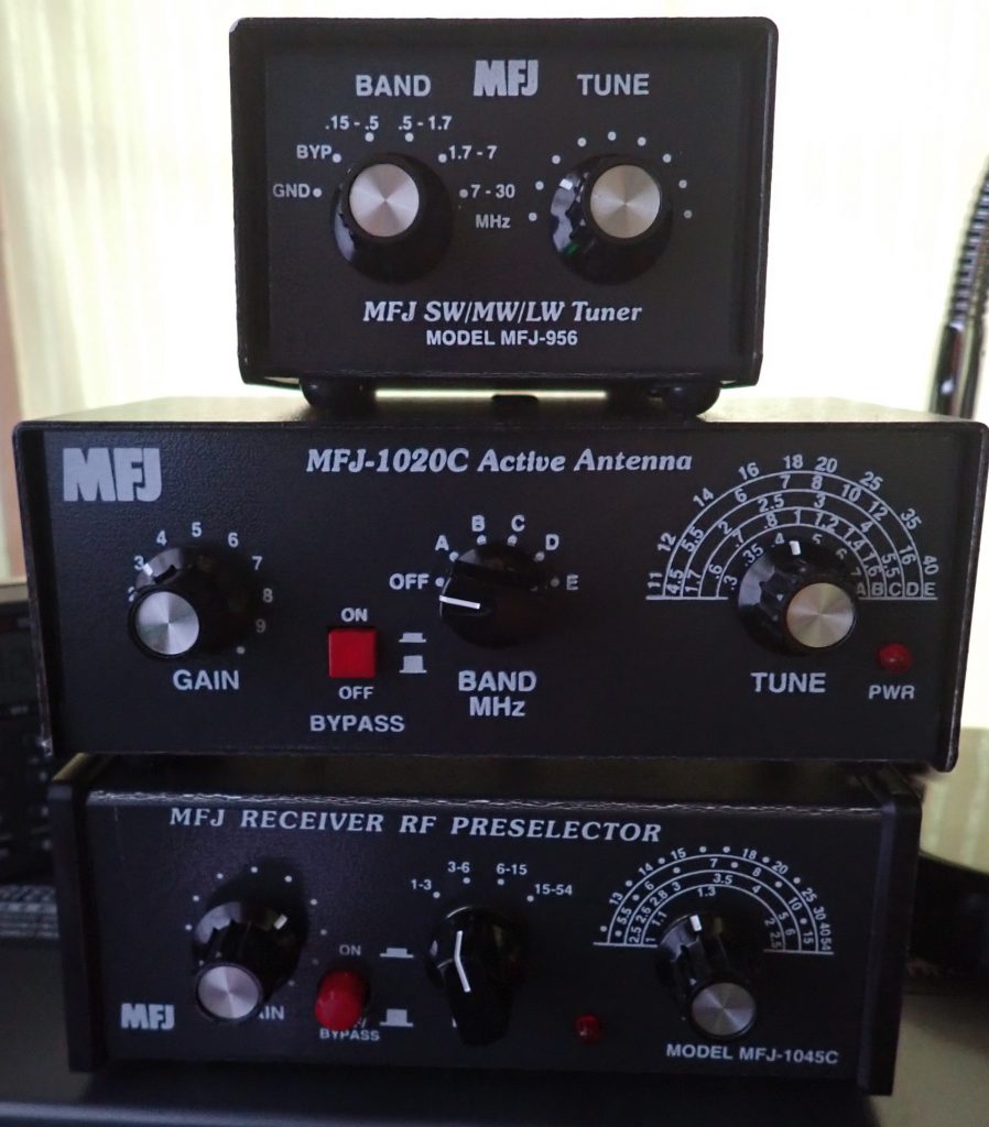
Along the way, I decided to test the MFJ 1020C active antenna/preselector, and I liked it pretty well. My conclusion was: Bearing in mind that it won’t improve every signal you want to hear, if you live in an antenna-challenged situation, the MFJ 1020C – particularly if you can get 20-50 feet of wire outdoors or run around the perimeter of a room – may be just what the doctor ordered.

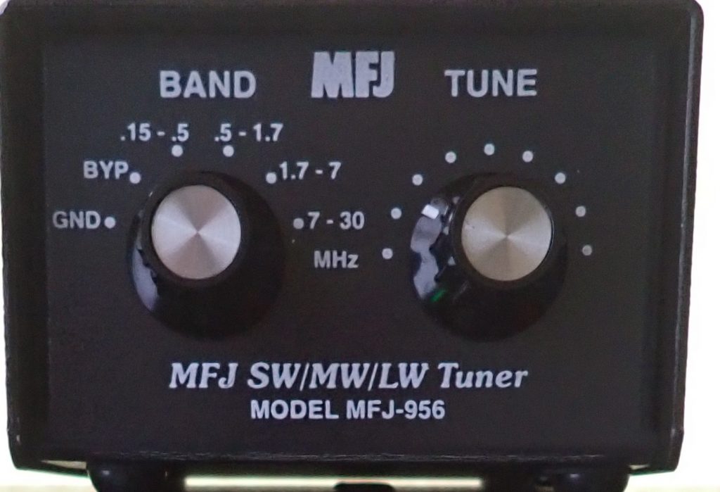
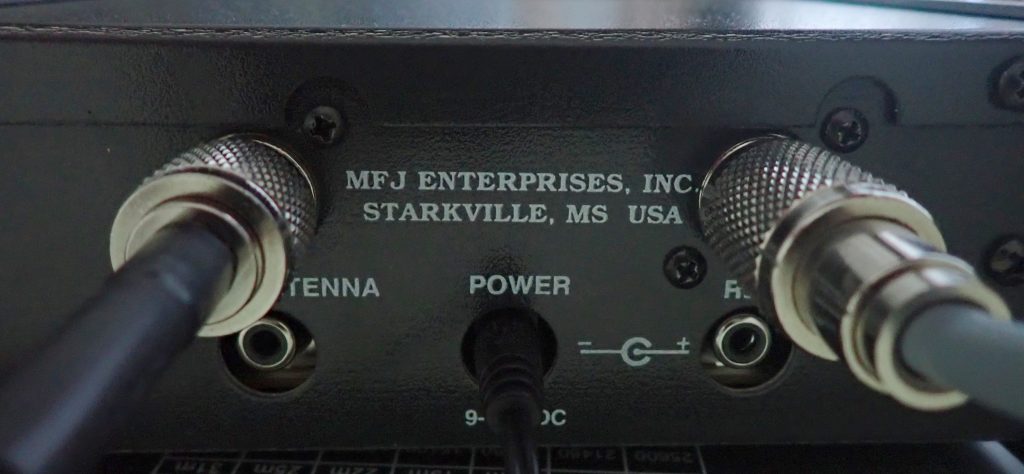
After my test of the 1020C, I had an online conversation with Andrew (grayhat), and he suggested that I might want to have a look at the MFJ 956 passive selector.  Its major claim to fame is: “Boost your favorite stations while rejecting images, intermod, and phantom signals!  The MFJ-956 Pre-Selector/Antenna Tuner greatly improves reception from .15 to 30 MHz — especially below 2MHz.  It has tuner bypass/ground receiver positions.  The MFJ-956 measures a compact 2 x 3 x 4 inches.

MFJ was kind enough to send a 956 to me, and while I did not test it below 2 MHz, I found that it proved very helpful in tuning in the BBC mid-winter broadcast to Antarctica. I started out with the MFJ 1020C. Lots of noise and fades. Reception was somewhat better using the 1020C (compared to bypass), but then I switched to MFJ 956. I found I could copy better with the 956, even though it provides no amplification. Tuning slightly off-peak offered the best copy, better than bypass. I was listening in USB. In all, it is a useful piece of gear.

While poking around the MFJ website I discovered the MFJ 1046 Receiver Preselector, 1.6-33 MHz. Among other claims, MFJ has this to say about the 1046: MFJs new Passive Preselector has extremely high dynamic range! It improves the performance of nearly any HF or shortwave receiver/transceiver. It vastly improves the most expensive receivers. Especially helpful to those with broadband front-ends that are prone to overload.

Sounds promising, I thought, so I emailed Thomas, SWLing’s Maximum Leader, to see if maybe MFJ would like me to have a look at one.

A happy accident

A few days later, package arrived.

I was unpacking it when the Brain Dudes interrupted.

Brain Dudes:  Hey!!

Me: What?!!

Brain Dudes: That thing look a little weird to you?

Me: Whaddya mean?

Brain Dudes: Look at the front . . . what do you see?

Me: Well, on left, a knob labeled GAIN; next to that, and ON/OFF button; moving to the right, a BAND selector switch, and finally a TUNE knob.

Brain Dudes: And what is the MFJ 1046 supposed to have?

Me: A big tuning knob, an ON/OFF switch, and a BAND selector switch . . . maybe this is an improved model . . .

Brain Dudes: How ‘bout you look on the back panel . . . what do you see?

Me: The usual connections for antenna and receiver . . . and a plug-in socket for an external power supply.

Brain Dudes:  Is a passive preselector supposed to have a power socket?

Me: No . . .

Brain Dudes: OK, final clue, Sherlock: suppose you read the label on the front panel.

Me: MFJ 1045C. Holy smokes! They sent me the wrong unit!

(I hear the Brain Dude yelling at someone in the background: “Finally, the light comes on! I told you switching to decaf was a bad idea!)

Brain dudes: So they sent you the wrong unit; suppose you test it anyway since it’s here.
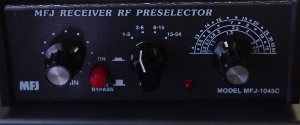
So I did. And it turns out that MFJ sending the 1045C instead of the 1046 was a happy accident because the 1045C, which is an active preselector, delivers excellent performance across the board.

This is what MFJ says about the 1045C: “Lets you copy weak signals. Rejects out-of-band signals, images. 1.8 to 54 MHz. Up to 20 dB gain. Gain control. Dual gate MOSFET, bipolar transistors for low noise, high gain. Connect 2 antennas, 2 receivers. Coax and phone jacks. 9-18 VDC or MFJ-1312D.

Once the antenna, receiver, and power supply are connected (I used the power supply that MFJ sent me with the 1020C), I operate the 1045C in much the same way as the 1020C:

  1. With the unit in BYPASS mode (the ON/OFF button out), tune the receiver to the frequency you want to hear.
  2. Set the GAIN knob to around 3 or 4.
  3. Set the BAND knob to the band with the MHz that you are tuned to.
  4. Press the ON/OFF/BYPASS button in. This turns on the active preselector and amplification circuits and a red light comes on to let you know the unit is activated.
  5. Slowly turn the TUNE knob back & forth. At some point in its tuning range, you will hear the signal and/or noise peak.
  6. Finally, adjust the GAIN knob for maximum intelligibility of the signal. Sometimes tuning slightly to the side of the peak works best.

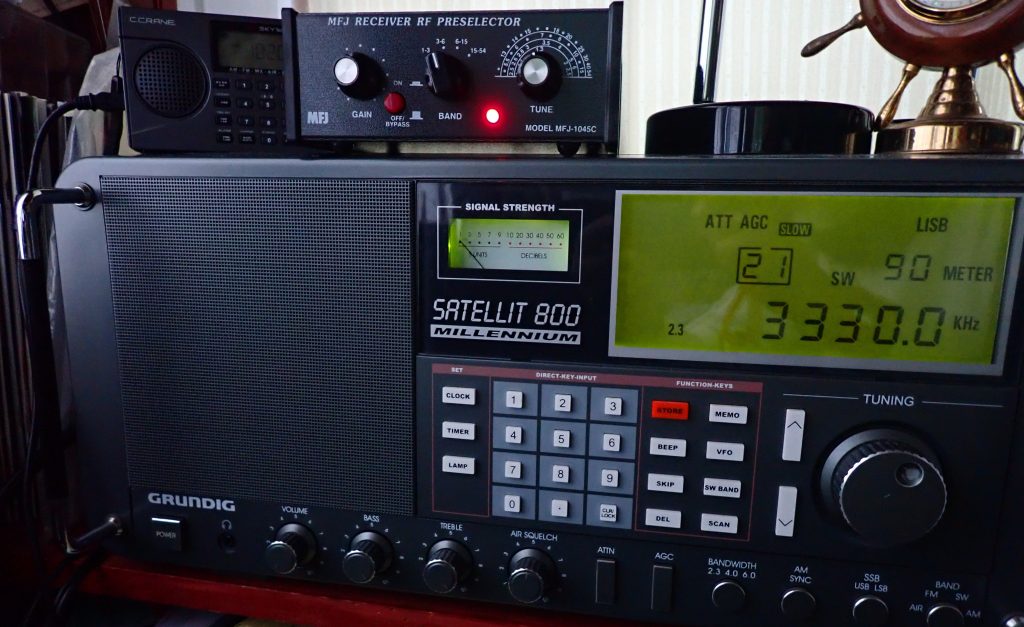
I tested the MFJ 1045C with my end-fed indoor antenna (see link above) and with the short dipole (also, see link above). I also did head-to-head comparisons with the MFJ 1020C and those two antennas.
The results

Here’s what I found:

  1. The indoor end-fed antenna (which is 45 long) out-performs the short dipole (which is 6 feet total length) in all cases. That’s no surprise, but bear in mind that not everyone has a situation in which they can deploy the longer antenna. The 6-foot dipole definitely out-performs the whip antenna on my Satellit 800.
  2. The 1045C has a broader range of amplification than the 1020C. It appears to reject adjacent channel interference as well or better than the 1020C, and, to my ear, the 1045C has a lower noise floor. If you turn the GAIN knob fully to the left, it gets to a position where it appears to actually attenuate the signal. And I never found a situation in which, if properly tuned, the signal delivered by the 1045C was at least equal to the bypass signal, and many times it was significantly better. In short, in the HF range the 1045C appears do to everything that the 1020C does (with the exception of the 1020C’s screw-in whip antenna) and do it better.
  3. When using the 1045C with a portable (my Tecsun 880), I found that I could hear the noise peaks better than with the 1020C, which is a great help in tuning for best performance.

So why would you chose the 1020C or the 956 over the 1045C? Short answer: if you are a MW or LW enthusiast. According to MFJ, the 1045C covers 1.8 to 54 MHz; the 1020C covers .3 to 40 MHz, and the 956 covers 150 kHz to 35 MHz.

However, if you are an HF weenie like I am who enjoys teasing out faint signals, and particularly if you are faced with a sub-optimal antenna situation, the MFJ 1045C, in my opinion, is definitely worth a try.

Click here to check out the MFJ-1045C.

Shameless plug: check out the SWLing Post Message Board there are often interesting discussions going on there.
Spread the radio love

Can the Eton Elite Satellit meet 2022 expectations?

Many thanks to SWLing Post contributor, Dan Robinson, for the following guest commentary:


The Elite Satellit: Can Eton Deliver to Radio Users Who Expect Higher QC and Feature Standards?

by Dan Robinson

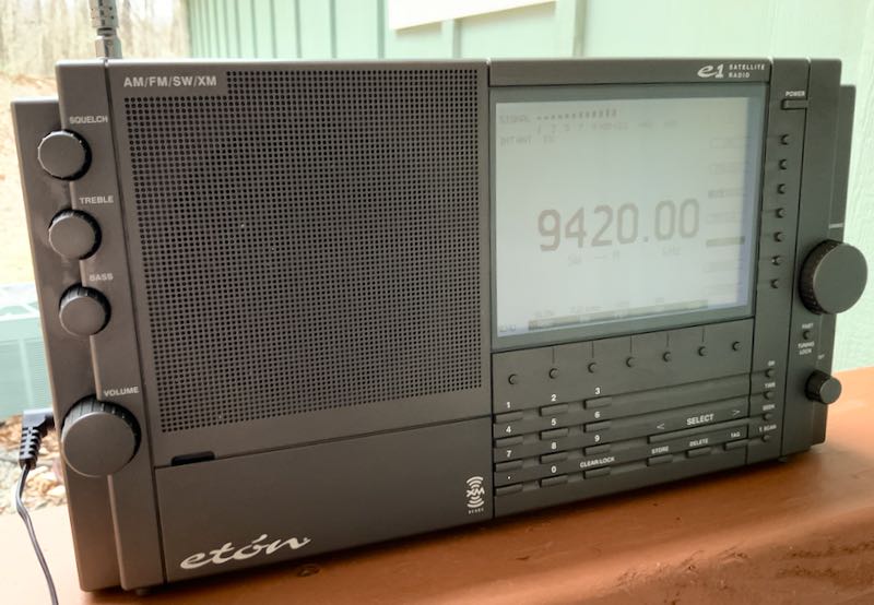
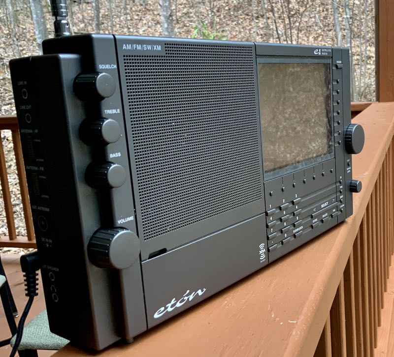
It’s been many years since the original E1 took the hobby world by storm. Everyone remembers the issues that plagued the E1, from the rubber coating that degraded over time, to display and encoder issues, and the calibration issues that frustrate some users.

In anticipation of the arrival of the Elite Satellit, I got both of my E1s out of storage — one in the 9xxx serial number range required a de-gooing session, accomplished quite well using Max Pro cleaner and 70% alcohol. It was interesting note, during that process, that the XM module on one side of the radio was more sensitive to color loss than other parts of the cabinet, reducing to an almost silver color when all was finished.

Original Eton E1 XM

Using the original E1s provided a reminder of how good these receivers were and still are, if you have managed to avoid display and encoder issues. The combination of PBT, triple selectivity and highly-effective SYNC was a blockbuster combination. The radio failed only in the area of quality control.

As Universal Radio and other distributors prepare to send out the first tranche of receivers, some thoughts are in order. The first is that one hopes Eton has lessons from the first go around regarding Quality Control. I have a sinking feeling about this based on my experiences in recent years reviewing receivers by Tecsun.

Eton needs to know that those who will buy the Elite Satellit, and that includes old-timers like myself but newcomers to the hobby, now have much higher standards specifically because of the features we have seen Tecsun and some other manufacturers put in portables.

Primarily, the presence of a recalibration capability really poses a challenge where the Elite Satellit is concerned. Discerning buyers no longer have to put up with a radio that has calibration and/or stability problems. This is why I am curious as to whether Eton included an adjustment function through software or an adjustment hole as with the original E1. So far, there has been no confirmation on this question from Eton or anyone else.

Original Eton E1 XM

With an older E1, tweaking of the master oscillator was possible through the small adjustment hold in the rear of the radio cabinet. This was tricky since in many units the hole was inconveniently located directly under one of the plastic ribs on the back.

I solved this problem by gently cutting a small section of one rib with a Dremel or similar tool, providing easier access. Still, adjustment has to be done carefully due to the sensitivity of the pot, and preferably with a non-metallic jewelers flat head screw driver. Even then, movements of the radio would often throw the radio back off.

But again, E1 users were spoiled by the recalibration capability which Tecsun included on receivers from the PL-880 to the 990x and 501s and even the PL-368, all of which provide a software method of zeroing frequency in SSB. Even Malahit SDRs have a fine adjustment setting in software.

If Eton has not taken this into account, and has not made any recalibration possible, I fear that it may face a good number of buyers who will simply return radios that suffer from significant frequency error. In short, a “good enough for government” approach by Eton when it comes to calibration QC is simply not going to be sufficient because for years now, Tecsun has been setting a higher standard.

Physical cosmetic issues too will also be an important indicator as to Eton’s attention to QC. If Eton learned its lesson from the rubberized cabinet fiasco, this should not be a major problem. But I would urge owners of the new Elite Satellit to examine your radio for QC issues, like LCD pixel problems, wobbly knobs and loose encoders, and issues with the telescopic antenna.

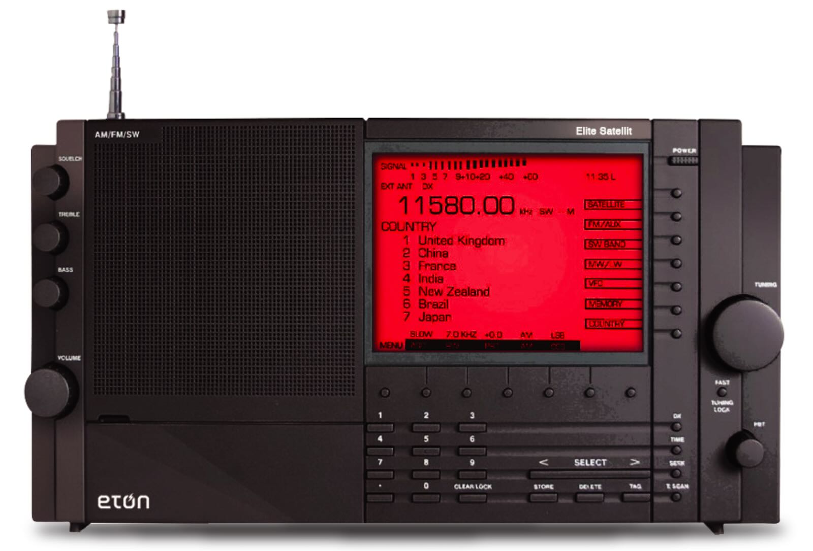
All of this becomes even more important because Eton is charging so much for this radio. Even taking inflation into account since the original E1 appeared, $599 for a radio that adds only HD and AIR band as features, but which still might suffer from QC problems is extremely high and I fear Eton may end up with numerous returns if the Elite Satellit fails in any key areas.

So, the clock ticks down to the moment when many of us will receive that box containing the Eton Elite Satellit. The question is will what is inside be able to meet the higher standards we have come to expect from a multi-band portable?

Spread the radio love